Table of Contents
Advertisement
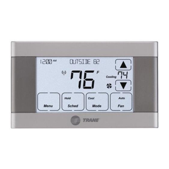
Indoor Temperature
Humidity
PM
Following Schedule
Outdoor
Scan to see
Installation and
help videos for
the 940 Sensor.
Cooling
Heating
Heat to:
Home
Away
Sleep
Zone
Fan
Clean
Screen
Auto
Auto
TZONE940AC52Z
Communicating
Sensor
with
Display
Table of Contents
Overview ............. 2
Operation ............ 3
Installation ........ 11
User &
Installation
Guide
Advertisement
Table of Contents

Related Manuals for Trane TZONE940AC52Z


Summary of Contents for Trane TZONE940AC52Z
- Page 1 TZONE940AC52Z Communicating Sensor Indoor Temperature Cooling Heating with Heat to: Humidity Display Home Away Sleep Following Schedule Outdoor Zone Table of Contents Clean Hold Screen Auto Auto Overview ..... 2 Operation .... 3 Installation ..11 User & Scan to see...
- Page 2 Section 1. General Information 1.1 Overview This sensor is a wall mounted low voltage control that allows a user to control the temperature in the respective zone. The sensor can be used in two different ways: • Stand-alone remote indoor temperature and relative humidity sensor.
- Page 3 Section 2. Operation Display Selection 2.1 Buttons and Indicators Selecting Cooling or Heating shows the System Status Setpoints/Adjustments setpoint and allows Notification manual temperature Icons adjustment. Room Temperature Setpoints Indoor Temperature Cooling Heating The desired Heat to: Indoor Humidity temperature the system Relative is targeting.
- Page 4 IMPORTANT: Do not use household cleaners or spray cleaners, including water spray to clean the 940 zone sensor screen or enclosure. Household cleaners and sprays may cause permanent damage to the zone sensor. Icons Alert Triangle – A critical alert has been detected. Contact servicing dealer. Signal Icon –...
- Page 5 Setpoints - The setpoint is the desired temperature for each mode (Heating or Cooling). Select the heating or cooling button to adjust the temperature for that mode. Using the red or blue arrow, adjust the temperature up or down. If scheduling is enabled on the 950 Control, changing the setpoint on the 940 Sensor overrides the scheduled setpoint until the next scheduled period.
- Page 6 Fan Mode - Fan Mode is a system-level function. Changing the fan mode at any sensor will change the system fan mode to reflect the last fan setting. Hold - This sensor offers three variations of Hold functionality that override the scheduled setpoints.
- Page 7 Temporary Hold - This feature temporarily overrides the Indoor Temperature Cooling Heating scheduled setpoints until the next scheduled period. Heat to: Humidity 1) Adjust Setpoint - Adjust the setpoint to the desired setting by pressing the up and down arrows. After approximately 5 seconds, the Holding Until: screen will display Holding Until with the time of the next scheduled Home...
- Page 8 Hold Until - This feature overrides the scheduled setpoint until a user selected time is reached. 1) Press Hold Two Times - Press Hold two times to enter Hold Until mode. Indoor Temperature Cooling Heating Heat to: Humidity 2) Adjust Setpoint - Adjust the setpoint to the desired setting. Holding Until: 3) Set End Time - Set the time to return to the scheduled setpoints.
- Page 9 2.2 940 Sensor’s Screen Layout The screen layout of the 940 Sensor can be customized through the 950 Control. MENU > SETTINGS > SCREEN SETTINGS > ZONE SENSOR Select the desired display settings. These settings will update on the 940 Communicating Sensor after selecting APPLY.
- Page 10 NOTE: If a zone without a 940 Communicating Sensor is currently displayed, the following screen will appear. Please note the zone in the top left. Press either of the green arrows to switch to the appropriate zone.
- Page 11 Section 3. Installation 3.1 Contents and Specifications The following parts are included in product model TZONE940AC52Z: 1 - Communicating Sensor 1 - Base 2 - Mounting screws/anchors 1 - Installation/User’s Guide Specification Description Product Model: ZONE940AC52Z Product: ComfortLink II™ Communicating Sensor Size: 5.5”...
- Page 12 3.2 Zone Sensor Location Considerations The 940 Communicating Sensor is designed for instal- 2 FEET lation in climate controlled living spaces. Optimum Zone It is recommended to place the sensor in central loca- tions with good circulation. 5 FEET Avoid exterior walls and areas too near windows, doors, vents or concealed pipes or chimneys.
- Page 13 3.3 Physical Mounting Remove cover by grasping at edges and Be sure wires are routed through the center gently pulling the cover straight towards of the base plate and are long enough to you. It should release without much effort. connect to terminals.
- Page 14 Mounting to studs: Drill 1/8” pilot holes in the 2 locations marked above. Mounting to drywall: Drill 3/16” pilot holes for anchors (included with the control) in the 2 locations marked above. Gently tap anchors into the holes. DRILL HOLES 1/8”...
- Page 15 3.4 Wiring Connect power leads to the D, R and B terminals. • Wire data to D. • Wire 24 VAC hot to R. • Wire common to B. Seal NOTE: All wall penetrations MUST be Hole sealed to prevent temperature biasing. WARNING CAUTION This information is intended for use by individuals possessing...
- Page 16 3.5 Setting Zone Address Indoor Temperature Setting up the 940 Sensor is a two-step process. System Zone Setup Number BOTH steps MUST be performed. Setting Cancel Clean Hold Screen STEP 1 – Setting the 940 Sensor’s address: Done 1. Verify that the Setup Number is “1” and if not adjust it using red/blue arrows.
- Page 17 STEP 2 – Assigning the 940 Sensor to the corresponding damper in the 950 Control. 1. From the 950 Control verify that is run- ning software version 2.2 or later. If not, a software upgrade is required before the 950 will recognize 940 Sensors. 2.
- Page 18 NOTE: If you need to re-enter this setup screen, press and hold INDOOR TEMPERATURE for approximately 5 seconds. Important: Once the 940 Sensor’s address has been selected and the sensor has been associated to a zone in the 950 Control, changing the address at the 940 Sensor will have no effect on the zone assignment.
- Page 19 3.7 Optional User Display Settings The setup screen allows changing of display settings. These features can be adjusted by changing the SETUP NUMBER and changing the SETTING range in the same manner as the Zone Address was set in the previous section. Please see the matrix below. NOTE: To enter this setup screen, press and hold INDOOR TEMPERATURE for approximately 5 seconds.
-
Page 20: Troubleshooting
3.8 Troubleshooting Troubleshooting Issues Icon Condition 950 Control Displays Solution Indoor temperature sensor An associated SOP.004.00 will Use the 950 Diagnostic has failed/stopped reporting be displayed on the 950 control screen to troubleshoot alert Alert Indoor humidity sensor has An associated SOP.004.03 will Use the 950 Diagnostic Icon failed/stopped reporting... - Page 21 BASE LIMITED WARRANTY Subject to the terms and conditions of this limited warranty, Trane U.S., Inc. (“Company’) extends a limited warranty against manufacturing defects for the product(s) identified in Tables 1, 1A, 1B attached hereto (“Products’) that are installed in a residential/multi-family application (personal, family or household purposes) under normal use and maintenance in the United States and Canada.
- Page 22 ELIGIBILITY REQUIREMENTS: The following items are required in order for the Products to be covered under this limited warranty: • The Products must be in the same location where they were originally installed. • The Products must be properly installed, operated, and maintained by a licensed HVAC service provider in accordance with the Product specifications or installation, operation, and maintenance instructions provided by Company with each Product.
- Page 23 Refer to your local laws for your specific rights under this limited warranty. Residential Systems 6200 Troup Highway, Tyler, TX 75707 Attn: Customer Relations Or visit our website at www.trane.com or www.americanstandardair.com...
- Page 24 Table 1A: Warranty Time Periods COVERAGE TERMS FOR RESIDENTIAL APPLICATIONS: Pursuant to the Trane U.S., Inc. (“Company”) limited warranty terms and conditions, the following Products are covered for the base time periods as stated below (“Base Limited Warranty period”). If registered, the Base Limited Warranty Periods for certain products will be extended as stated below (“Registered Limited Warranty Period”).