
Related Manuals for Supero SUPERSERVER 8046B-6RF


Summary of Contents for Supero SUPERSERVER 8046B-6RF
- Page 1 UPER ® 8046B-6RF UPER ERVER 8046B-TRF UPER ERVER USER’S MANUAL Revision 1.0...
- Page 2 The information in this User’s Manual has been carefully reviewed and is believed to be accurate. The vendor assumes no responsibility for any inaccuracies that may be contained in this document, makes no commitment to update or to keep current the information in this manual, or to notify any person or organization of the updates.
-
Page 3: About This Manual
SuperServer 8025C-3R. In- stallation and maintenance should be performed by experienced technicians only. The SuperServer 8046B-6RF/8046B-TRF is a high-end quad processor server based on the SC748TQ-R1400BP 4U tower/rackmount server chassis and the Su- per X8QB6-F/X8QBE-F serverboard. - Page 4 You should thoroughly familiarize yourself with this chapter for a general overview of safety precautions that should be followed when installing and servicing the SuperServer 8046B-6RF/8046B-TRF. Chapter 5: Advanced Serverboard Setup Chapter 5 provides detailed information on the X8QB6-F/X8QBE-F serverboard, including the locations and functions of connectors, headers and jumpers.
- Page 5 Preface Notes...
-
Page 6: Table Of Contents
UPER ERVER 8046B-6RF/8046B-TRF User's Manual Table of Contents Chapter 1 Introduction Overview ......................1-1 Serverboard Features ..................1-2 Processors ...................... 1-2 Memory ......................1-2 Serial Attached SCSI (X8QB6-F) ..............1-2 Serial ATA ....................... 1-2 PCI Expansion Slots ..................1-2 I/O Ports ......................1-3 IPMI ......................... - Page 7 Table of Contents Preparing to Power On ..................2-11 Chapter 3 System Interface Overview ......................3-1 Control Panel Buttons ..................3-1 Reset ....................... 3-1 Power ......................3-1 Control Panel LEDs ..................3-2 Power Fail ....................... 3-2 Overheat/Fan Fail ................... 3-2 NIC2 ........................ 3-2 NIC1 ........................
- Page 8 UPER ERVER 8046B-6RF/8046B-TRF User's Manual 5-10 Jumper Settings .................... 5-19 5-11 Onboard Indicators ..................5-21 5-12 SAS and SATA Ports ..................5-22 Chapter 6 Advanced Chassis Setup Static-Sensitive Devices .................. 6-1 Precautions ..................... 6-1 Unpacking ....................... 6-2 Control Panel ....................6-3 System Fans ....................
-
Page 9: Chapter 1 Introduction
Chapter 1 Introduction Overview The SuperServer 8046B-6RF/8046B-TRF is a high-end server comprised of two main subsystems: the SC748TQ-R1400B 4U/tower chassis and the X8QB6-F/ X8QBE-F quad processor serverboard. Please refer to our web site for information on operating systems that have been certifi ed for use with the 8046B-6RF/8046B- TRF (www.supermicro.com). -
Page 10: Serverboard Features
UPER ERVER 8046B-6RF/8046B-TRF User's Manual Serverboard Features At the heart of the SuperServer 8046B-6RF/8046B-TRF lies the X8QB6-F/X8QBE- F, a quad processor serverboard based on the Intel 7500 + ICH10R chipset. (See Figure 1-1 for a block diagram of the chipset). -
Page 11: I/O Ports
Chapter 1: Introduction I/O Ports The I/O ports include one COM port (an additional COM header is located on the serverboard), a VGA (monitor) port, two USB 2.0 ports, two Gb Ethernet ports and a dedicated IPMI LAN port. IPMI IPMI (Intelligent Platform Management Interface) is a hardware-level interface speci- fi... -
Page 12: Server Chassis Features
UPER ERVER 8046B-6RF/8046B-TRF User's Manual Server Chassis Features The following is a general outline of the main features of the SC748TQ-R1400B server chassis. System Power The SC748TQ-R1400B features a redundant (two separate power modules) 1400W high-effi ciency power supply. This power redundancy feature allows you to replace a failed power supply without shutting down the system. -
Page 13: System Block Diagram
Chapter 1: Introduction Figure 1-1. Intel 7500 Chipset: System Block Diagram Note: This is a general block diagram. See Chapter 5 for details. 6.4GT/s 6.4GT/s FBD0 FBD0 SMI 6.4GT/s SMI 6.4GT/s FBD1 FBD1 SMI 6.4GT/s SMI 6.4GT/s FBD2 FBD2 SMI 6.4GT/s SMI 6.4GT/s FBD3 FBD3... -
Page 14: Contacting Supermicro
UPER ERVER 8046B-6RF/8046B-TRF User's Manual Contacting Supermicro Headquarters Address: Super Micro Computer, Inc. 980 Rock Ave. San Jose, CA 95131 U.S.A. Tel: +1 (408) 503-8000 Fax: +1 (408) 503-8008 Email: marketing@supermicro.com (General Information) support@supermicro.com (Technical Support) Web Site: www.supermicro.com Europe Address: Super Micro Computer B.V. -
Page 15: Chapter 2 Server Installation
Chapter 2: Server Installation Chapter 2 Server Installation Overview This chapter provides a quick setup checklist to get your 8046B-6RF/8046B-TRF up and running. Following these steps in the order given should enable you to have the system operational within a minimum amount of time. This quick setup assumes that your system has come to you with the processors and memory preinstalled. -
Page 16: Choosing A Setup Location
UPER ERVER 8046B-6RF/8046B-TRF User's Manual Choosing a Setup Location • Leave enough clearance in front of the rack to enable you to open the front door completely (~25 inches) and approximately 30 inches of clearance in the back of the rack to allow for suffi cient airfl ow and ease in servicing. •... -
Page 17: Rack Mounting Considerations
Chapter 2: Server Installation • Allow the hot plug SAS/SATA drives and power supply modules to cool before touching them. • Always keep the rack's front door and all panels and components on the servers closed when not servicing to maintain proper cooling. Rack Mounting Considerations Ambient Operating Temperature If installed in a closed or multi-unit rack assembly, the ambient operating tempera-... -
Page 18: Installing The System Into A Rack
UPER ERVER 8046B-6RF/8046B-TRF User's Manual Installing the System into a Rack This section provides information on installing the system into a rack unit. Rack installation requires the use of the optional rackmount kit If the system has already been mounted into a rack or if you are using it as a tower, you can skip ahead to Sections 2-5 and 2-6. -
Page 19: Identifying The Sections Of The Rack Rails
Chapter 2: Server Installation Figure 2-1. Removing the Chassis Top Cover and Feet Chassis Feet Chassis Cover Chassis Cover Lock Identifying the Sections of the Rack Rails The chassis package includes two rack rail assemblies in the rack mounting kit. Each assembly consists of two sections: an inner fi... - Page 20 UPER ERVER 8046B-6RF/8046B-TRF User's Manual Figure 2-2. Identifying the Inner Rails and Chassis Handles Inner Rails Chassis Handle Screw Chassis Rail Chassis Handle Screw Locate the inner rails (2) and screws (12) in the shipping package. Align the inner rails against the chassis, as shown. Confi rm that the rails are fl...
- Page 21 Chapter 2: Server Installation Figure 2-3. Installing the Inner Rack Rails Secure to the Rear of the Rack Attach to Rear Bracket Secure to the Front of the Rack Figure 2-4. Assembling the Outer Rails...
- Page 22 UPER ERVER 8046B-6RF/8046B-TRF User's Manual Installing the Chassis into a Rack Confi rm that chassis includes the inner rails and the outer rails. Align the chassis rails with the front of the rack rails (C). Slide the chassis rails into the rack rails, keeping the pressure even on both sides (you may have to depress the locking tabs when inserting).
-
Page 23: Checking The Serverboard Setup
Chapter 2: Server Installation Checking the Serverboard Setup After setting up the the system, you may need to open the unit to make sure all the connections have been made. Accessing the Inside of the System (see Figure 2-5) If rack mounted, fi rst release the retention screws that secure the unit to the rack. - Page 24 UPER ERVER 8046B-6RF/8046B-TRF User's Manual Figure 2-5. Accessing the Inside of the System 2-10...
-
Page 25: Preparing To Power On
Chapter 2: Server Installation Preparing to Power On Next, you should check to make sure the peripheral drives and the hard drives and backplane have been properly installed and all connections have been made. Checking the Drives To install components into the 5.25" drive bays, you will need to remove the top/left chassis cover. - Page 26 UPER ERVER 8046B-6RF/8046B-TRF User's Manual Notes 2-12...
-
Page 27: Chapter 3 System Interface
Chapter 3: System Interface Chapter 3 System Interface Overview There are several LEDs on the control panel as well as others on the hard drive carriers to keep you constantly informed of the overall status of the system as well as the activity and health of specifi... -
Page 28: Control Panel Leds
UPER ERVER 8046B-6RF/8046B-TRF User's Manual Control Panel LEDs The control panel located on the front of the SC748TQ-R1400 chassis has fi ve LEDs. These LEDs provide you with critical information related to different parts of the system. This section explains what each LED indicates when illuminated and any corrective action you may need to take. -
Page 29: Nic1
Chapter 3: System Interface NIC1 Indicates network activity on LAN1 when fl ashing . Indicates HDD activity. On the 8046B-6RF/8046B-TRF this light indicates HDD and/or DVD-ROM drive activity when fl ashing. Power Indicates power is being supplied to the system's power supply units. This LED should normally be illuminated when the system is operating. -
Page 30: Hard Drive Carrier Leds
UPER ERVER 8046B-6RF/8046B-TRF User's Manual Hard Drive Carrier LEDs Each drive carrier has two LEDs that function when a drive has been installed: SAS Drives • Green: When illuminated, the green LED on the drive carrier indicates the drive is powered on. When fl ashing it indicates data is being accessed on a drive. If this LED is not lit, it means no power is being provided for the drive. -
Page 31: Chapter 4 System Safety
System Safety Electrical Safety Precautions Basic electrical safety precautions should be followed to protect yourself from harm and the SuperServer 8046B-6RF/8046B-TRF from damage: • Be aware of the locations of the power on/off switch on the chassis as well as the room's emergency power-off switch, disconnection switch or electrical outlet. -
Page 32: General Safety Precautions
Contact technical support for details and support. General Safety Precautions Follow these rules to ensure general safety: • Keep the area around the SuperServer 8046B-6RF/8046B-TRF clean and free of clutter. • The SuperServer 8046B-6RF/8046B-TRF weighs approximately 65.5 lbs. (29.8 kg) when fully loaded. -
Page 33: Esd Precautions
Chapter 4: System Safety • After accessing the inside of the system, close the system back up and secure it to the rack unit with the retention screws after ensuring that all connections have been made. ESD Precautions Electrostatic Discharge (ESD) is generated by two objects with different electrical charges coming into contact with each other. -
Page 34: Operating Precautions
UPER ERVER 8046B-6RF/8046B-TRF User's Manual Operating Precautions Care must be taken to assure that the chassis cover is in place when the 8046B- 6RF/8046B-TRF is operating to assure proper cooling. Out of warranty damage to the system can occur if this practice is not strictly followed. Figure 4-1. -
Page 35: Chapter 5 Advanced Serverboard Setup
Chapter 5: Advanced Serverboard Setup Chapter 5 Advanced Serverboard Setup This chapter covers the steps required to install the X8QB6-F/X8QBE-F serverboard into the chassis, connect the data and power cables and install add-on cards. All serverboard jumpers and connections are also described. A layout and quick refer- ence chart are included in this chapter for your reference. -
Page 36: Unpacking
UPER ERVER 8046B-6RF/8046B-TRF User's Manual Unpacking The serverboard is shipped in antistatic packaging to avoid electrical static dis- charge. When unpacking the board, make sure the person handling it is static protected. Serverboard Installation This section explains the fi rst step of physically mounting the X8QB6-F/X8QBE-F into the SC748TQ-R1400BP chassis. -
Page 37: Connecting Cables
Chapter 5: Advanced Serverboard Setup Connecting Cables Now that the serverboard is installed, the next step is to connect the cables to the board. These include the data (ribbon) cables for the peripherals and control panel and the power cables. Connecting Data Cables The cables used to transfer data from the peripheral devices have been carefully routed to prevent them from blocking the fl... -
Page 38: I/O Ports
UPER ERVER 8046B-6RF/8046B-TRF User's Manual Figure 5-1. Control Panel Header Pins Ground FP PWRLED 3.3 V ID_UID_SW/3/3V Stby HDD LED NIC1 Link LED NIC1 Activity LED NIC2 Activity LED NIC2 Link LED Blue+ (OH/Fan Fail/ Red+ (Blue LED Cathode) PWR FaiL/UID LED) Power Fail LED 3.3V Reset... -
Page 39: Installing The Processor And Heatsink
Chapter 5: Advanced Serverboard Setup Installing the Processor and Heatsink Avoid placing direct pressure to the top of the processor package. Always remove the power cord fi rst before adding, removing or changing any hardware components. Notes: Always connect the power cord last and remove it before adding, remov- ing or changing any components. -
Page 40: Installing A Passive Cpu Heatsink
UPER ERVER 8046B-6RF/8046B-TRF User's Manual Align pin 1 on the CPU with pin 1 on the CPU socket. Once both the CPU and the socket CPU Pin 1 are aligned, carefully lower the CPU straight down into the socket. (To avoid damaging the CPU or the socket, do not rub the CPU against the surface of the socket or its pins.) -
Page 41: Removing The Passive Heatsink
Chapter 5: Advanced Serverboard Setup Warning: We do not recommend removing the CPU or the heat sink. However, if you do need to uninstall the heat sink, please follow these instructions to avoid damaging the CPU or the CPU socket. Removing the Passive Heatsink Power off the system and unplug the power cord from the power supply. -
Page 42: Memory Support
UPER ERVER 8046B-6RF/8046B-TRF User's Manual Installing Memory CAUTION! Exercise extreme care when installing or removing DIMM modules to prevent any possible damage. Memory Support The X8QB6-F/X8QBE-F can support up to 512 GB of registered ECC DDR3- 1333/1066/800 memory. (DDR-1333 memory will run at 1066 MHz.) Memory mod- ules of the same size and speed should be used within the same bank. - Page 43 Chapter 5: Advanced Serverboard Setup Confi guring Memory Follow the tables below for correct memory confi guration. Processors and their Corresponding Memory Modules CPU# Corresponding DIMM Slots CPU 1 P1-1A P1-2A P1-3A P1-4A P1-5A P1-6A P1-7A P1-8A CPU2 P2-1A P2-2A P2-3A P2-4A P2-5A...
-
Page 44: Adding Pci Add-On Cards
UPER ERVER 8046B-6RF/8046B-TRF User's Manual Adding PCI Add-On Cards The 8046B-6RF/8046B-TRF has four PCI slots for add-on cards. Installing an Add-on Card Begin by removing the PCI slot shield for the slot you wish to populate. Fully seat the card into the riser card slot, pushing down with your thumbs evenly on both sides of the card. -
Page 45: Serverboard Details
Chapter 5: Advanced Serverboard Setup Serverboard Details Figure 5-5. X8QB6-F/X8QBE-F Layout (not drawn to scale) LAN1 USB0/1 COM1 LED26 FAN10 UID_LED (LOWER) BMC_HB UID_SWITCH JUIDB1 FAN9 FAN8 Intel 82576 Winbond BMCRST BMC CTRL LAN CTRL IPMI_LAN LAN2 (UPPER) JBT1 Intel ICH 10R BIOS Intel IOH 7500... -
Page 46: X8Qb6-F/X8Qbe-F Quick Reference
UPER ERVER 8046B-6RF/8046B-TRF User's Manual X8QB6-F/X8QBE-F Quick Reference Jumper Description Default Setting JBT1 Clear CMOS See Section 5-9 JPG1 VGA Enable Pins 1-2 (Enabled) JPL1 LAN1/LAN2 Enable Pins 1-2 (Enabled) JPS1 (X8QB6-F only) SAS2 Enable Pins 1-2 (Enabled) JPT1 TPM Enable Pins 1-2 (Enabled) JWD1 Watch Dog... -
Page 47: Connector Defi Nitions
Chapter 5: Advanced Serverboard Setup Connector Defi nitions ATX Power 24-pin Connector Pin Defi nitions Pin# Defi nition Pin # Defi nition Main ATX Power Supply +3.3V +3.3V Connector -12V +3.3V The primary power supply connec- tor (JPW3) meets the SSI EPS 12V PS_ON specifi... -
Page 48: Super Server 8046B-6Rf/8046B-Trf User's Manual
UPER ERVER 8046B-6RF/8046B-TRF User's Manual OH/Fan Fail/UID LED Pin Defi nitions Overheat (OH)/Fan Fail/PWR Fail/ (JF1) UID LED Pin# Defi nition Connect an LED cable to pins 7 and Vcc/Front UID LED 8 of JF1 to use the Overheat/Fan Fail/ OH/Fan Fail LED Power Fail and UID LED connections. - Page 49 Chapter 5: Advanced Serverboard Setup Power On LED Power LED Pin Defi nitions (JF1) The Power On LED connector is lo- Pin# Defi nition cated on pins 15 and 16 of JF1 (use 5V Stby JLED for a 3-pin connector). This Control connection is used to provide LED indication of power being supplied to...
- Page 50 UPER ERVER 8046B-6RF/8046B-TRF User's Manual TPM Header/Port 80 TPM/Port 80 Header Pin Defi nitions A Trusted Platform Module/Port 80 Pin # Defi nition Pin # Defi nition header is located at LPCI to provide LCLK TPM support and Port 80 connection LFRAME# <(KEY)>...
- Page 51 Chapter 5: Advanced Serverboard Setup Serial Ports Serial Port Pin Defi nitions A serial port is included on the Pin # Defi nition Pin # Defi nition serverboard backpanel. See the table on the right for pin defi nitions. Ground USB2/3, USB5 Universal Serial Bus (USB) USB0/1...
- Page 52 UPER ERVER 8046B-6RF/8046B-TRF User's Manual Unit Identifi er Switch A Unit Identifi er (UID) switch LED Indi- cators are included on the serverboard. The UID switch is located next to the UID Switch LAN ports on the backplane. The UID Pin# Defi...
-
Page 53: 5-10 Jumper Settings
Chapter 5: Advanced Serverboard Setup 5-10 Jumper Settings Explanation of Jumpers To modify the operation of the serverboard, jumpers can be used to choose between optional settings. Connector Pins Jumpers create shorts between two pins to change the function of the con- nector. - Page 54 UPER ERVER 8046B-6RF/8046B-TRF User's Manual LAN1/2 Enable/Disable LAN1/2 Enable/Disable Change the setting of jumper JPL1 to Jumper Settings enable or disable the LAN1/LAN2 Eth- Jumper Setting Defi nition ernets port on the serverboard. See the Pins 1-2 Enabled table on the right for jumper settings. Pins 2-3 Disabled The default setting is enabled.
-
Page 55: 5-11 Onboard Indicators
Chapter 5: Advanced Serverboard Setup 5-11 Onboard Indicators LAN1/2 LED LAN1/2 LEDs (Connection Speed Indicator) The Ethernet ports have two LEDs. On LED Color Defi nition each port, one LED indicates activity NC or 10 Mb/s while the other LED may be green, Green 100 Mb/s amber or off to indicate the speed of... -
Page 56: 5-12 Sas And Sata Ports
UPER ERVER 8046B-6RF/8046B-TRF User's Manual 5-12 SAS and SATA Ports SAS Port Pin Defi nitions Pin # Defi nition SAS Ports Ground Eight SAS ports are supported on the serverboard. See the table on the right for pin defi ni- Ground tions. -
Page 57: Chapter 6 Advanced Chassis Setup
Chapter 6: Advanced Chassis Setup Chapter 6 Advanced Chassis Setup This chapter covers the steps required to install components and perform mainte- nance on the SC748TQ-R1400BP chassis. For component installation, follow the steps in the order given to eliminate the most common problems encountered. If some steps are unnecessary, skip ahead to the step that follows. -
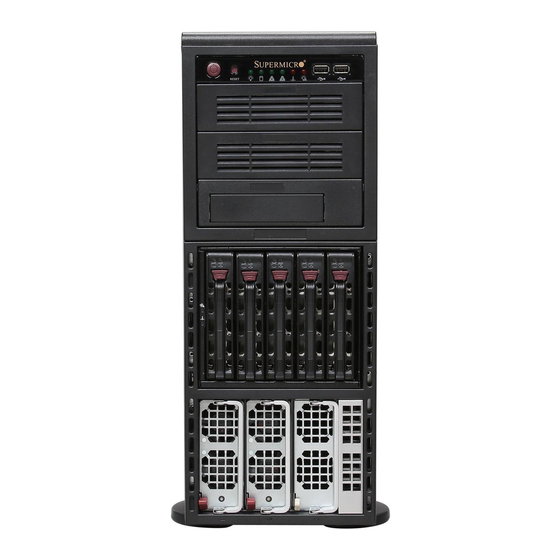
Page 58: Unpacking
UPER ERVER 8046B-6RF/8046B-TRF User's Manual Unpacking When unpacking the system, make sure the person handling it is static protected. Figure 6-1. System Front View System LEDs USB Ports Main Power System Reset 5.25" Drive Bays (3) Hard Drive Bays (5) 2x Power Supply Modules (module on the right is a dummy) -
Page 59: Control Panel
Chapter 6: Advanced Chassis Setup Control Panel The front control panel must be connected to the JF1 connector on the serverboard to provide you with system status and alarm indications. A ribbon cable has bundled these wires together to simplify this connection. Connect the cable from JF1 on the serverboard (making sure the red wire plugs into pin 1) to the appropriate connector on the front control panel PCB. -
Page 60: System Fans
UPER ERVER 8046B-6RF/8046B-TRF User's Manual System Fans Three 9-cm chassis cooling fans (located in the center of the chassis) provide cooling airfl ow while three 8-cm exhaust fans expel hot air from the chassis. The fans should all be connected to headers on the serverboard (see Chapter 5). Each power supply module also has a cooling fan. - Page 61 Chapter 6: Advanced Chassis Setup Figure 6-3. Removing Chassis Fans Figure 6-4. Removing the Air Shroud...
-
Page 62: Drive Bay Installation
UPER ERVER 8046B-6RF/8046B-TRF User's Manual Drive Bay Installation Hard Drives The hard drives are mounted in drive carriers to simplify their installation and removal from the chassis. These carriers also help promote proper airfl ow for the drives. For this reason, even empty carriers without hard drives installed must remain in the chassis. - Page 63 Chapter 6: Advanced Chassis Setup Figure 6-4. Removing a Hard Drive Carrier Figure 6-5. Mounting a Hard Drive in a Carrier Regardless of how many hard drives are installed, all drive carriers must remain in the drive bays to promote proper airfl ow. Enterprise level hard disk drives are recommended for use in Supermicro chassis and servers.
-
Page 64: Installing Components In The 5.25" Drive Bays
UPER ERVER 8046B-6RF/8046B-TRF User's Manual Installing Components in the 5.25" Drive Bays The 8046B-6RF/8046B-TRF has three empty 5.25" drive bays. A fl oppy drive, hard drives or DVD/CD-ROM drives can be installed into these 5.25" drive bays. Removing the Empty Drive Bay First power down the system. -
Page 65: Power Supply
Hard Drive Tray Hard Drive Power Supply The SuperServer 8046B-6RF/8046B-TRF has a redundant 1400 watt power supply consisting of two power modules. (A third may be added for triple redundancy.) Each power module has an auto-switching capability, which enables it to automatically sense and operate at a 100V - 240V input voltage. - Page 66 UPER ERVER 8046B-6RF/8046B-TRF User's Manual Removing the Power Supply First unplug the AC power cord that corresponds to the failed power supply unit. The power cords are oriented the same as the modules are (the left/top power cord corresponds to the left/top power module). Depress the locking tab on the power supply unit and pull the unit straight out by the handle.
-
Page 67: Chapter 7 Bios
Chapter 7: BIOS Chapter 7 BIOS Introduction This chapter describes the AMI BIOS Setup Utility for the X8QB6-F/X8QBE-F. The AMI ROM BIOS is stored in a Flash EEPROM and can be easily updated. This chap- ter describes the basic navigation of the AMI BIOS Setup Utility setup screens. Starting BIOS Setup Utility To enter the AMI BIOS Setup Utility screens, press the <Delete>... -
Page 68: Main Setup
UPER ERVER 8046B-6RF/8046B-TRF User's Manual Starting the Setup Utility Normally, the only visible Power-On Self-Test (POST) routine is the memory test. As the memory is being tested, press the <Delete> key to enter the main menu of the AMI BIOS Setup Utility. From the main menu, you can access the other setup screens. - Page 69 Chapter 7: BIOS System Overview: The following BIOS information will be displayed: System Time/System Date Use this option to change the system time and date. Highlight System Time or Sys- tem Date using the arrow keys. Enter new values through the keyboard and press <Enter>.
-
Page 70: Advanced Setup Confi Gurations
UPER ERVER 8046B-6RF/8046B-TRF User's Manual Advanced Setup Confi gurations Use the arrow keys to select Boot Setup and press <Enter> to access the submenu items. Warning: Be sure to select the correct setting for each item in this section. A wrong setting selected may cause the system to malfunction. Boot Features Quick Boot If enabled, this feature will skip certain tests during POST to reduce the time needed... -
Page 71: Processor And Clock Options
Chapter 7: BIOS PS/2 Mouse Support Select Enabled to enable PS/2 Mouse support. Select Auto to enable the onboard PS/2 mouse when a PS/2 mouse is detected. The options are Enable, Disabled, and Auto. Wait For 'F1' If Error This forces the system to wait until the 'F1' key is pressed when an error occurs. The options are Disabled and Enabled. - Page 72 UPER ERVER 8046B-6RF/8046B-TRF User's Manual Sever Class Use this item to identify the server class for your system so that the prefectcher settings listed below can be correctly confi gured. The options are Enterprise, HPC (High Performance Cluster) and Custom (for customized servers). Hardware Prefetcher (Available when supported by the CPU) If enabled, the hardware prefetcher will prefetch streams of data and instructions from the main memory to the L2 cache to improve CPU performance.
- Page 73 Chapter 7: BIOS CPU Multi-Core Enable/Disable (Available when supported by the CPU) Select Enabled to enable multi-core CPU support to enhance CPU performance for the following CPU Cores. The options are Disabled and Enabled. • Core 0/Core 1/Core 2/Core 3/Core 4/Core 5/Core 6/Core 7 A20M When the A20M# pin is enabled, it will force address bit 20 to zero (to be masked) to emulate the address wraparound for the real-address mode at 1 MB.
-
Page 74: Advanced Chipset Control
UPER ERVER 8046B-6RF/8046B-TRF User's Manual ACPI T State When this feature is enabled, CPU Throttling state will be reported in the ACPI (Advanced Confi guration and Power Interface) protocol. The options are Enabled and Disabled. Advanced Chipset Control The items included in the Advanced Settings submenu are listed below. CPU Bridge Confi... - Page 75 Chapter 7: BIOS QPI (Quick Path Interconnect) Links Speed Use this feature to set data transfer speed for QPI Link connections. The options are Slow and Fast. QPI Frequency Select (Available if the item - QPI Link Speed is set to Fast) This feature is used to set desired QPI frequency.
- Page 76 UPER ERVER 8046B-6RF/8046B-TRF User's Manual • Inter-Socket Mirrored S0 (Socket 0) to S1 (Socket 1), and S2 (Socket 2) to S3 (Socket 3), • Inter-Socket Mirrored S0 (Socket 0) to S2 (Socket 2) and S1 (Socket 1) to S3 (Socket 3), •...
- Page 77 Chapter 7: BIOS performance. Select Close to use memory safe mode. Select Adaptive to balance safety and performance. The options are Close, Open and Adaptive. Scheduler Policy Use this feature to confi gure Scheduler_Policy settings. The scheduler is used to translate memory read/write commands into memory sub-commands for easy execution.
- Page 78 UPER ERVER 8046B-6RF/8046B-TRF User's Manual Maximum Read Request Size This feature is used to set the maximum read request size for a PCI-Express device. The options are Auto, 128 Bytes, 256 Bytes, 512 Bytes, 1024 Bytes, 2048 Bytes, 4096 Bytes, and Maximum supported. Active State Power Management Select Enabled to use the power management for signal transactions between the PCI Express L0 and L1 Links.
- Page 79 Chapter 7: BIOS always be enabled. When the item - USB Functions is set to Disabled, the user has the option to enable or disable USB 2.0 Controller.) HDA Controller Select Enabled to enable the High-Defi nition Audio Controller. The settings are Enabled and Disabled.
- Page 80 UPER ERVER 8046B-6RF/8046B-TRF User's Manual IDE/SATA Confi guration When this submenu is selected, the AMI BIOS will automatically detect the presence of the IDE/SATA devices, and displays the following items. SATA#1 Confi guration If Compatible is selected, it sets SATA#1 to the legacy_compatible mode. Select- ing Enhanced sets SATA#1 to the native SATA mode.
- Page 81 Chapter 7: BIOS contact your manufacturer or install an ATA/133 IDE controller card that supports 48-bit LBA mode. The options are Disabled and Auto. Block (Multi-Sector Transfer) Block Mode boosts the IDE drive performance by increasing the amount of data transferred.
- Page 82 UPER ERVER 8046B-6RF/8046B-TRF User's Manual Select SWDMA2 to allow BIOS to use Single Word DMA mode 2. It has a data transfer rate of 8.3 MB/s. Select MWDMA0 to allow BIOS to use Multi-Word DMA mode 0. It has a data transfer rate of 4.2 MB/s.
- Page 83 Chapter 7: BIOS IDE Detect Timeout (sec) Use this feature to set the timeout value to allow BIOS to detect the ATA, ATAPI devices installed in the system. The options are 0 (sec), 5, 10, 15, 20, 25, 30, and PCI/PnP Confi...
- Page 84 UPER ERVER 8046B-6RF/8046B-TRF User's Manual Onboard SAS OPROM Select Enabled to enable Onboard SAS Option ROM which will allow you to boot the computer using a SAS device. The options are Enabled and Disabled. Onboard LAN Option ROM Select Select iSCSI to use iSCSI Option ROMs to boot the computer. Select PXE to use PXE Option ROMs to boot the computer.
- Page 85 Chapter 7: BIOS BIOS EHCI Hand-Off Select Enabled to support BIOS Enhanced Host Controller Interface to provide a workaround solution for an operating system that does not support EHCI Hand-Off technology. When enabled, the EHCI Interface will be changed from the BIOS- controlled to the OS-controlled.
- Page 86 UPER ERVER 8046B-6RF/8046B-TRF User's Manual NUMA Support Select Enabled to enable Non-Uniform Memory Access support to improve CPU performance for a system that has an OS with NUMA support. The options are Enabled and Disabled. Chipset ACPI Confi guration This feature is used to confi gure Chipset ACPI (Advanced Confi guration and Power Interface) settings.
- Page 87 Chapter 7: BIOS Event Log Confi guration View Event Log Use this option to view the System Event Log. Mark All Events as Read This option marks all events as read. The options are OK and Cancel. Clear Event Log This option clears the Event Log memory of all messages.
- Page 88 UPER ERVER 8046B-6RF/8046B-TRF User's Manual CPU 1 Temperature ~ CPU 4 Temperature/System Temperature 1 Reading~ System Temperature 4 Reading This feature displays current temperature readings for the CPU and the System as specifi ed above. The following items will be displayed for your reference only: CPU 1 Temperature ~ CPU 4 Temperature The CPU thermal technology that reports absolute temperatures (Celsius/Fahr- enheit) has been upgraded to a more advanced feature by Intel in its newer...
- Page 89 Chapter 7: BIOS Notes: 1. The system may shut down if it continues for a long period to prevent damage to the CPU. 2. The information provided above is for your reference only. For more information on thermal management, please refer to Intel’s web site at www.Intel.com.
- Page 90 UPER ERVER 8046B-6RF/8046B-TRF User's Manual Status of BMC The Baseboard Management Controller (BMC) manages the interface between system management software and platform hardware. This item displays the status of the current BMC controller. IPMI Firmware Version This item displays the current IPMI Firmware Version. View BMC System Event Log This feature displays the BMC System Event Log (SEL).
- Page 91 Chapter 7: BIOS Set LAN Confi guration This feature allows the user to confi gure the IPMI LAN adapter with a network ad- dress as shown in the following graphics. Channel Number - This feature displays the channel number. Channel Number Status - This feature returns the channel status for the Channel Number selected above: "Channel Number is OK"...
-
Page 92: Gateway Address
UPER ERVER 8046B-6RF/8046B-TRF User's Manual Current Mac Address in BMC The BIOS will automatically enter the current Mac address in BMC for this ma- chine; however it may be overwritten. Mac addresses are 6 two-digit hexadecimal numbers (Base 16, 0 ~ 9, A, B, C, D, E, F) separated by dots. (i.e., 00.30.48. D0.D4.60). - Page 93 Chapter 7: BIOS Serial Port Number This feature allows the user decide which serial port to be used for Console Redi- rection. The options are COM 1 and COM 2. Base Address, IRQ This item displays the based address and IRQ of the serial port specifi ed. Serial Port Mode Use this item to set the serial port mode for Console Redirection.
- Page 94 UPER ERVER 8046B-6RF/8046B-TRF User's Manual Trusted Computing (Optional) TCG/TPM Support Select Yes on this item and enable the TPM jumper on the motherboard to enable TCG (TPM 1.1/1.2)/TPM support to improve data integrity and network security. The options are No and Yes. If this feature is set to Yes, the following items will display.
-
Page 95: Boot Confi Guration
Chapter 7: BIOS Boot Confi guration Use this feature to confi gure boot settings. Boot Device Priority This feature allows the user to specify the sequence of priority for the Boot Device. The settings are 1st boot device, 2nd boot device, 3rd boot device, 4th boot device, 5th boot device and Disabled. -
Page 96: Security Settings
UPER ERVER 8046B-6RF/8046B-TRF User's Manual Security Settings The AMI BIOS provides a Supervisor and a User password. If you use both pass- words, the Supervisor password must be set fi rst. Supervisor Password This item indicates if a Supervisor password has been entered for the system. "Not Installed"... -
Page 97: Exit Options
Chapter 7: BIOS Password Check Select Setup for the system to check for a password at Setup. Select Always for the system to check for a password at bootup. The options are Setup and Always. Boot Sector Virus Protection When Enabled, the AMI BIOS displays a warning if any program (or virus) issues a Disk Format command or attempts to write to the boot sector of the hard disk drive. - Page 98 UPER ERVER 8046B-6RF/8046B-TRF User's Manual Load Optimal Defaults To set this feature, select Load Optimal Defaults from the Exit menu and press <Enter>. Then, select OK to allow the AMI BIOS to automatically load Optimal De- faults to the BIOS Settings. The Optimal settings are designed for maximum system performance but may not work best for all computer applications.
-
Page 99: Appendix A Post Codes
Appendix A: POST Codes Appendix A POST Codes During the POST (Power-On Self-Test) routines, which are performed each time the system is powered on, errors may occur. Non-fatal errors are those which, in most cases, allow the system to continue the boot-up process. - Page 100 UPER ERVER 8046B-6RF/8046B-TRF User's Manual Notes...
-
Page 101: Appendix B System Specifi Cations
Appendix B: System Specifi cations Appendix B System Specifi cations Processors Four Intel® Xeon® 7500 Series processors inLGA-1567 sockets Note: Please refer to our web site for a complete listing of supported processors. Chipset Intel 7500 + ICH10R BIOS 8 Mb AMIBIOS® Flash ROM Memory Capacity Supports up to 512 GB of registered ECC or unbuffered ECC DDR3- 1333/1066/978/800 memory. - Page 102 UPER ERVER 8046B-6RF/8046B-TRF User's Manual Chassis SC748TQ-R1200 (tower/4U rackmount) Dimensions (as tower): (WxHxD) 7 x 17.8 x 29.4 in. (178 x 452 x 747 mm) Weight Gross (Bare Bone): 65.5 lbs. (29.8 kg.) System Cooling Six heavy-duty 8-cm cooling fans (fan speed controlled by BIOS setting) System Input Requirements AC Input Voltage: 100-240 VAC Rated Input Current: 6A (115V) to 15A (240V)
- Page 103 Appendix B: System Specifi cations California Best Management Practices Regulations for Perchlorate Materials: This Perchlorate warning applies only to products containing CR (Manganese Dioxide) Lithium coin cells. “Perchlorate Material-special handling may apply. See www.dtsc.ca.gov/hazardouswaste/perchlorate”...
- Page 104 UPER ERVER 8046B-6RF/8046B-TRF User's Manual (continued from front) The products sold by Supermicro are not intended for and will not be used in life support systems, medical equipment, nuclear facilities or systems, aircraft, aircraft devices, aircraft/emergency com- munication devices or other critical systems whose failure to perform be reasonably expected to result in signifi...