
Related Manuals for Supero SUPERO SuperServer 5037MC-H8TRF


Summary of Contents for Supero SUPERO SuperServer 5037MC-H8TRF
- Page 1 UPER ® UPER ERVER Super Microcloud 5037MC-H8TRF USER’S MANUAL Revision 1.0...
- Page 2 This product, including software and docu- mentation, is the property of Supermicro and/or its licensors, and is supplied only under a license. Any use or reproduction of this product is not allowed, except as expressly permitted by the terms of said license.
-
Page 3: About This Manual
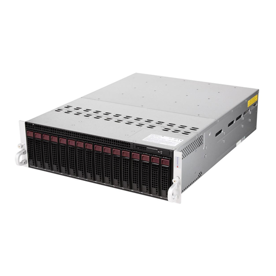
Preface Preface About This Manual This manual is written for professional system integrators and PC technicians. It provides information for the installation and use of the SuperServer 5037MC-H8TRF. Installation and maintenance should be performed by experienced technicians only. The SuperServer 5037MC-H8TRF is an 8-node, Microcloud server system based on the SC938H-R1620B 3U chassis and eight X9SCD-F motherboards. - Page 4 UPER ERVER 5037MC-H8TRF User's Manual Chapter 4: System Safety You should thoroughly familiarize yourself with this chapter for a general overview of safety precautions that should be followed when installing and servicing the SuperServer 5037MC-H8TRF. Chapter 5: Advanced Motherboard Setup Chapter 5 provides detailed information on the X9SCD-F motherboard, including the locations and functions of connectors, headers and jumpers.
- Page 5 Preface Notes...
-
Page 6: Table Of Contents
Other Features ....................1-3 Server Chassis Features ................1-4 System Power ....................1-4 Front Control Panel ..................1-4 Cooling System ....................1-4 Contacting Supermicro ..................1-5 Chapter 2 Server Installation Overview ......................2-1 Unpacking the System ..................2-1 Preparing for Setup ..................2-1 Choosing a Setup Location ................ - Page 7 Table of Contents Checking the Motherboard Setup ..............2-10 Preparing to Power On ................. 2-12 Chapter 3 System Interface Overview ......................3-1 Control Panel Buttons ..................3-1 Power Button/LED ................... 3-1 LEDs ........................ 3-2 Power Failure LED ..................3-2 Hard Drive Carrier LEDs ................. 3-3 Node LEDs ......................
- Page 8 UPER ERVER 5037MC-H8TRF User's Manual 5-11 Jumper Settings .................... 5-14 5-12 Onboard Indicators ..................5-16 5-13 SATA Drive Connections ................5-17 5-14 Installing Software ..................5-17 Supero Doctor III ................... 5-18 Chapter 6 Advanced Chassis Setup Static-Sensitive Devices .................. 6-1 Precautions .....................
-
Page 9: Chapter 1 Introduction
SC938H-R1620B 3U chassis and eight X9SCD-F motherboards. Please refer to our web site for information on operating systems that have been certifi ed for use with the 5037MC-H8TRF (www.supermicro. com). In addition to the motherboard and chassis, various hardware components have been included with the 5037MC-H8TRF, as listed below: •... -
Page 10: Motherboard Features
Each X9SCD-F supports a single Intel E3-1200 Series processor in an LGA 1155 socket. Please refer to the motherboard description pages on our web site for a complete listing of supported processors (www.supermicro.com). Memory The X9SCD-F has four DIMM slots that can support up to 32 GB of ECC DDR3- 1333/1066 UDIMM. -
Page 11: Ipmi
IPMI IPMI (Intelligent Platform Management Interface) is a hardware-level interface speci- fi cation that provides remote access, monitoring and administration for Supermicro server platforms. IPMI allows server administrators to view a server’s hardware status remotely, receive an alarm automatically if a failure occurs, and power cycle a system that is non-responsive. -
Page 12: Server Chassis Features
UPER ERVER 5037MC-H8TRF User's Manual Server Chassis Features The following is a general outline of the main features of the SC938H-R1620B server chassis. System Power The SC938H-R1620B features a redundant (two separate power modules) 1620W high-effi ciency power supply. This power redundancy feature allows you to replace a failed power supply without shutting down the system. -
Page 13: Contacting Supermicro
Super Micro Computer, Inc. 980 Rock Ave. San Jose, CA 95131 U.S.A. Tel: +1 (408) 503-8000 Fax: +1 (408) 503-8008 Email: marketing@supermicro.com (General Information) support@supermicro.com (Technical Support) Web Site: www.supermicro.com Europe Address: Super Micro Computer B.V. Het Sterrenbeeld 28, 5215 ML... - Page 14 UPER ERVER 5037MC-H8TRF User's Manual Notes...
-
Page 15: Chapter 2 Server Installation
Chapter 2: Server Installation Chapter 2 Server Installation Overview This chapter provides a quick setup checklist to get your 5037MC-H8TRF up and running. Following these steps in the order given should enable you to have the system operational within a minimum amount of time. This quick setup assumes that your system has come to you with the processors and memory preinstalled. -
Page 16: Choosing A Setup Location
UPER ERVER 5037MC-H8TRF User's Manual Choosing a Setup Location • Leave enough clearance in front of the rack to enable you to open the front door completely (~25 inches) and approximately 30 inches of clearance in the back of the rack to allow for suffi cient airfl ow and ease in servicing. •... -
Page 17: Rack Mounting Considerations
Chapter 2: Server Installation • Allow the hot plug SATA drives and power supply modules to cool before touch- ing them. • Always keep the rack's front door and all panels and components on the servers closed when not servicing to maintain proper cooling. Rack Mounting Considerations Ambient Operating Temperature If installed in a closed or multi-unit rack assembly, the ambient operating tempera-... -
Page 18: Installing The System Into A Rack
UPER ERVER 5037MC-H8TRF User's Manual Installing the System into a Rack This section provides information on installing the chassis into a rack unit with the rails provided. There are a variety of rack units on the market, which may mean that the assembly procedure will differ slightly from the instructions provided. -
Page 19: Locking Tabs
Chapter 2: Server Installation Locking Tabs Each inner rail has a locking tab. This tab locks the chassis into place when installed and pushed fully into the rack. These tabs also lock the chassis in place when fully extended from the rack. This prevents the server from coming completely out of the rack when when the chassis is pulled out for servicing. -
Page 20: Installing The Inner Rails On The Chassis
UPER ERVER 5037MC-H8TRF User's Manual Inner Rails Figure 2-3. Installing the Inner Rails Figure 2-4. Inner Rails Installed on the Chassis Installing The Inner Rails on the Chassis Installing the Inner Rails 1. Confi rm that the left and right inner rails have been correctly identifi ed. 2. -
Page 21: Installing The Outer Rails On The Rack
Chapter 2: Server Installation Figure 2-5. Extending and Releasing the Outer Rails Installing the Outer Rails on the Rack Installing the Outer Rails 1. Press upward on the locking tab at the rear end of the middle rail. 2. Push the middle rail back into the outer rail. 3. -
Page 22: Standard Chassis Installation
UPER ERVER 5037MC-H8TRF User's Manual Ball-Bearing Shuttle Figure 2-6. Installing the Chassis into a Rack Standard Chassis Installation 1. Confi rm that the inner rails are properly installed on the chassis. 2. Confi rm that the outer rails are correctly installed on the rack. 3. -
Page 23: Optional Quick Installation Method
Chapter 2: Server Installation Optional Quick Installation Method The following quick installation method may be used to install the chassis onto a rack. 1. Install the inner rails on the chassis as previously described on page 2-6. 2. Install the whole rail assembly onto the rack as described on page 2-7. 3. -
Page 24: Checking The Motherboard Setup
UPER ERVER 5037MC-H8TRF User's Manual Checking the Motherboard Setup After setting up the the system, you may need to open the unit to make sure all the connections have been made. Note: Before operating the system for the fi rst time, it is important to remove the protective fi... - Page 25 Chapter 2: Server Installation Figure 2-8. Accessing the Inside of the System Remove Three Screws Remove Film From Vents Warning: Except for short periods of time, do NOT operate the server without the cover in place. The chassis cover must be in place to allow proper airfl...
-
Page 26: Preparing To Power On
UPER ERVER 5037MC-H8TRF User's Manual Preparing to Power On Checking the Drives 1. Depending upon your system's confi guration, your system may have hard drives already installed. If you need to install hard drives, please refer to Chapter 6. Checking the Airfl ow 1. -
Page 27: Chapter 3 System Interface
Chapter 3: System Interface Chapter 3 System Interface Overview LEDs are included on the control panel, the serverboard nodes and on the drive carriers to keep you constantly informed of the overall status of the system. The SC938 features four separate control panels on the handles of the chassis to control the nodes. -
Page 28: Leds
UPER ERVER 5037MC-H8TRF User's Manual LEDs Power Failure LED This red LED is illuminated only when a power failure occurs. The LED will illuminate when any node is powered-on and one of the power supplies fails. This LED is off during normal operation. -
Page 29: Hard Drive Carrier Leds
Chapter 3: System Interface Hard Drive Carrier LEDs The hard drives ued in the SC938 chassis are installed in drive carriers. Each drive carrier has two LEDs located on the front of the carrier. • Green: Each drive carrier has a green LED. When illuminated, this LED indicates drive activity. -
Page 30: Power Button And Led
UPER ERVER 5037MC-H8TRF User's Manual Figure 3-3. Rear Node LED Indicators Power Button and LED (Green) UIO Button and LED (Blue) Failure LED (Red) Power Button and LED This button will power on the node individually. It is illuminated green when the node is powered on, it is off (unilluminated ) when the node is powered off. -
Page 31: Chapter 4 System Safety
Chapter 4: System Safety Chapter 4 System Safety Electrical Safety Precautions Basic electrical safety precautions should be followed to protect yourself from harm and the SuperServer 5037MC-H8TRF from damage: • Be aware of the locations of the power on/off switch on the chassis as well as the room's emergency power-off switch, disconnection switch or electrical outlet. -
Page 32: General Safety Precautions
UPER ERVER 5037MC-H8TRF User's Manual • Motherboard Battery: CAUTION - There is a danger of explosion if the onboard battery is installed upside down, which will reverse its polarites (see Figure 4-1). This battery must be replaced only with the same or an equivalent type recom- mended by the manufacturer (CR2032). -
Page 33: Esd Precautions
Chapter 4: System Safety • After accessing the inside of the system, close the system back up and secure it to the rack unit with the retention screws after ensuring that all connections have been made. ESD Precautions Electrostatic Discharge (ESD) is generated by two objects with different electrical charges coming into contact with each other. -
Page 34: Operating Precautions
UPER ERVER 5037MC-H8TRF User's Manual Operating Precautions Care must be taken to assure that the chassis cover is in place when the 5037MC- H8TRF is operating to assure proper cooling. Out of warranty damage to the system can occur if this practice is not strictly followed. Figure 4-1. -
Page 35: Chapter 5 Advanced Motherboard Setup
Chapter 5: Advanced Motherboard Setup Chapter 5 Advanced Motherboard Setup This chapter covers the steps required to install the motherboard modules into the chassis, connect the data and power cables and install add-on cards. All mother- board jumpers and connections are also described. A layout and quick reference chart are included in this chapter for your reference. -
Page 36: Unpacking
UPER ERVER 5037MC-H8TRF User's Manual Unpacking The motherboard is shipped in antistatic packaging to avoid electrical static discharge. When unpacking the board, make sure the person handling it is static protected. Motherboard Installation The X9SCD-F motherboards have been preinstalled into carriers to simplify install- ing and removing the nodes from the SC938H-R1620B chassis. -
Page 37: Processor And Heatsink Installation
CPU socket cap is in place and none of the socket pins are bent; otherwise, contact your retailer immediately. • Refer to the Supermicro web site for updates on CPU support. Installing an LGA1155 Processor 1. Press the load lever to release the load plate, which covers the CPU socket, from its locked position. - Page 38 UPER ERVER 5037MC-H8TRF User's Manual 3. Use your thumb and your index fi nger to hold the CPU at the top center edge and the bottom center edge of the CPU. 4. Align the CPU key (the semi-circle cutouts) against the socket keys. Once aligned, carefully lower the CPU straight down to the socket.
-
Page 39: Installing A Heatsink
Chapter 5: Advanced Motherboard Setup CPU properly installed Load lever locked into place. Make sure "A" points are under B Installing a Heatsink 1. With the node removed, remove the air shroud as described in Section 6-7. 2. Do not apply any thermal grease to the heatsink or the CPU die; the required amount has already been applied. -
Page 40: Installing Memory
UPER ERVER 5037MC-H8TRF User's Manual Installing Memory CAUTION! Exercise extreme care when installing or removing DIMM modules to prevent any possible damage. How to Install Memory 1. Insert the desired number of DIMMs into the memory slots, starting with DIMM1A, then DIMM2A, DIMM1B, DIMM2B. Pay attention to the notch along the bottom of the module to prevent incorrect installation. -
Page 41: Installing And Removing Dimms
Chapter 5: Advanced Motherboard Setup Installing and Removing DIMMs Position the DIMM module's bottom key so that it aligns with the receptive point on the slot. Notches Push a lock/release tab to the Release release position. Make sure that the side notches of the DIMM module aligns with the lock/release tab of the slot as Release... -
Page 42: Guidelines For Populating Memory
UPER ERVER 5037MC-H8TRF User's Manual Guidelines for Populating Memory When installing memory modules, the DIMM slots should be populated in the fol- lowing order: DIMM1A, DIMM2A, DIMM1B and DIMM2B. • Always use DDR3 DIMM modules of the same size, type and speed. •... - Page 43 Chapter 5: Advanced Motherboard Setup 7. Close the PCI card slot clip to secure the expansion card. Note: The PCI slot shields protect the motherboard and its components from EMI and aid in proper ventilation, so make sure there is always a shield covering each unused slot.
-
Page 44: Motherboard Details
UPER ERVER 5037MC-H8TRF User's Manual Motherboard Details Figure 5-4. X9SCD-F Layout PWR BTN/LED JKVM1 IPMI LED5 UID LED UID BUTTON LAN1 LED4 MICRO LP JPB1 SLOT1 SPKR1 JI2C1 JPG1 JWD1 JI2C2 JBT1 JTPM1 JBT1 CMOS CLEAR JUSB2 I-SATA4 I-SATA4 BATT JWF1 JWF1 CPU1... -
Page 45: X9Scd-F Quick Reference
Chapter 5: Advanced Motherboard Setup X9SCD-F Quick Reference Jumper Description Default Setting JPB1 BMC Enable/Disable Pins 1-2 (Enabled) JPG1 Onboard VGA Enable/Disable Pins 1-2 (Enabled) JWD1 Watch Dog Timer RST/NMI Selection Pins 1-2 (Reset) JBT1 CMOS Clear See Section 5-11 JI2C1, JI2C2 SMB to PCI Slots See Section 5-11... -
Page 46: Connector Defi Nitions
UPER ERVER 5037MC-H8TRF User's Manual Connector Defi nitions IF + POWER This edge connector, located on the opposite end of the motherboard from the I/O back panel, is used to connect the motherboard to the backplane of the server chassis. Through this connector, the motherboard will receive its power and com- municate with the rest of the system (hard drives, warning lamps, etc). -
Page 47: 5-10 I/O Port Defi Nitions
Chapter 5: Advanced Motherboard Setup SATA DOM Power (JWF1) The SATA DOM Power on JWF1 is used to supply power to SATA Disk-on-Module (DOM) solid-state storage devices. 5-10 I/O Port Defi nitions KVM Port The KVM port supports two USB devices and VGA and UART interfaces. -
Page 48: 5-11 Jumper Settings
UPER ERVER 5037MC-H8TRF User's Manual 5-11 Jumper Settings Explanation of Jumpers To modify the operation of the mother- board, jumpers can be used to choose Connector between optional settings. Jumpers Pins create shorts between two pins to change the function of the connector. Pin 1 is identifi... - Page 49 Chapter 5: Advanced Motherboard Setup VGA Enable (JPG1) VGA Enable/Disable Jumper Settings JPG1 allows the user to enable the Jumper Setting Defi nition onboard VGA connector (through the Pins 1-2 Enabled KVM). Close pins 1~2 to enable the Pins 2-3 Disabled VGA.
-
Page 50: 5-12 Onboard Indicators
UPER ERVER 5037MC-H8TRF User's Manual 5-12 Onboard Indicators IPMI Dedicated LAN Port An IPMI Dedicated LAN port installed Link LED Activity LED on the I/O back panel. The yellow LED IPMI on the right indicates activity, while the green LED on the left indicates the speed of the connection. -
Page 51: 5-13 Sata Drive Connections
5-14 Installing Software After the hardware has been installed, you should fi rst install the operating system and then the drivers. The necessary drivers are all included on the Supermicro CDs that came packaged with your motherboard. Driver/Tool Installation Display Screen Note: Click the icons showing a hand writing on paper to view the readme fi... -
Page 52: Supero Doctor Iii
UPER ERVER 5037MC-H8TRF User's Manual Supero Doctor III The Supero Doctor III program is a Web base management tool that supports remote management capability. It includes Remote and Local Management tools. The local management is called SD III Client. The Supero Doctor III program included on the CD-ROM that came with your motherboard allows you to monitor the environment and operations of your system. - Page 53 Supero Doctor III Interface Display Screen (Remote Control) Note: SD III Software Revision 1.0 can be downloaded from our Web Site at: ftp://ftp. supermicro.com/utility/Supero_Doctor_III/. You can also download the SDIII User's Guide at: <http://www.supermicro.com/PRODUCT/Manuals/SDIII/UserGuide.pdf>. For Linux, we will recommend using Supero Doctor II.
- Page 54 UPER ERVER 5037MC-H8TRF User's Manual Notes 5-20...
-
Page 55: Chapter 6 Advanced Chassis Setup
Chapter 6: Advanced Chassis Setup Chapter 6 Advanced Chassis Setup This chapter covers the steps required to install components and perform mainte- nance on the SC938H-R1620B chassis. For component installation, follow the steps in the order given to eliminate the most common problems encountered. If some steps are unnecessary, skip ahead to the step that follows. -
Page 56: Removing The Chassis Cover
UPER ERVER 5037MC-H8TRF User's Manual Removing the Chassis Cover Remove Three Screws Remove Film From Vents Figure 6-1. Removing the Chassis Cover IMPORTANT: Before operating the SC938H for the fi rst time, it is important to re- move the protective fi lm covering the ventilation openings on the top of the chassis. These vents provide proper ventilation and cooling for the system. -
Page 57: Corresponding Nodes, Fans And Hard Drives
Chapter 6: Advanced Chassis Setup Corresponding Nodes, Fans and Hard Drives The SC938H chassis contains eight individual motherboards contained in separate nodes. Each node controls two hard drives and shares a fan with the node beside it. Note that if a node is pulled out of the chassis, the hard drives associated with that node will power-down. -
Page 58: Removing And Installing Hard Drives
UPER ERVER 5037MC-H8TRF User's Manual Removing and Installing Hard Drives The SC938H features sixteen hot-swappable hard drives. These hard drives are contained in drive carriers and may be removed without powering-down the system. Removing Hard Drive Carriers from the Chassis 1. - Page 59 Chapter 6: Advanced Chassis Setup Dummy Drive Drive Carrier Figure 6-4. Removing a Dummy Drive from the Drive Carrier The hard drives are mounted in drive carriers to simplify their installation and re- moval from the chassis. These carriers also help promote proper airfl ow through the drive bays.
- Page 60 Regardless of how many hard drives are installed, all drive carriers must remain in the drive bays to promote proper airfl ow. Enterprise level hard disk drives are recommended for use in Supermicro chassis and servers. For information on recommended HDDs, visit the...
-
Page 61: Removing And Installing The Backplane
Chapter 6: Advanced Chassis Setup Removing and Installing the Backplane The backplane is attached to the fan bracket, which is located in the midsection of the chassis. In the unlikely event of a backplane failure, follow the instructions below to replace it. Removing the Backplane and Fan Bracket Assembly Removing the Backplane and Fan Bracket from the Chassis 1. -
Page 62: Removing The Backplane From The Fan Bracket
UPER ERVER 5037MC-H8TRF User's Manual Figure 6-7. Removing the Backplane from the Fan Bracket Removing the Backplane from the Fan Bracket Removing the Backplane 1. Remove the eight screws securing the two side mounting brackets to the sides of the fan bracket and set them aside for later use. Remove the side mounting brackets. -
Page 63: Installing The Backplane Onto The Fan Bracket
Chapter 6: Advanced Chassis Setup Figure 6-8. Installing the Backplane onto the Fan Bracket Installing the Backplane onto the Fan Bracket Installing the Backplane 1. Ensure that all power has been disconnected from the chassis. 2. Hold the backplane by its edges and carefully place it against the fan mount- ing bracket, aligning the mounting holes in the backplane with those in the fan bracket. -
Page 64: Installing The Backplane And Fan Bracket Assembly
UPER ERVER 5037MC-H8TRF User's Manual Figure 6-9. Installing the Backplane and Fan Bracket Installing the Backplane and Fan Bracket Assembly Installing the Backplane and Fan Bracket 1. Ensure that the chassis has been disconnected from any power source. 2. Remove the chassis cover as described in Section 6-2. 3. -
Page 65: Removing And Installing Motherboard Nodes
Chapter 6: Advanced Chassis Setup Removing and Installing Motherboard Nodes Release Tab Node Power LED Node Power Button Node Handle Figure 6-10. Removing Nodes from the System The SC938H chassis comes equipped with eight removable nodes, each one con- taining an individual motherboard. Removing these nodes will also power-down the corresponding hard drives. -
Page 66: Installing The Air Shroud
UPER ERVER 5037MC-H8TRF User's Manual Installing an Air Shroud Air shrouds concentrate airfl ow to maximize fan effi ciency. The SC938H chassis requires that air shrouds be used in each node. Installing the Air Shroud 1. Make sure that the motherboard expansion card (if present) and all compo- nents are properly installed in each motherboard node. -
Page 67: System Fans
Chapter 6: Advanced Chassis Setup System Fans Four 8-cm fans circulate air through the chassis to lower the internal temperature. The SC938H system fans are designed to be easily changed, with no tools required and no need to remove any other parts inside the chassis. See Section 6-3 to de- termine which nodes and hard drives are cooled by each system fan. -
Page 68: Power Supply
In the unlikely event that one of the power supplies needs to be replaced, one power supply can be removed without powering-down the system. Replacement power supply units may be ordered directly from Supermicro See the contact information in the Preface of this manual or visit www.supermicro.com. - Page 69 Chapter 6: Advanced Chassis Setup Changing the Power Supply 1. Unplug the AC power cord from the failed power supply. 2. With the system running, press the release tab at the top of the power supply 3. Push and hold the release tab on the back of the power supply. 4.
- Page 70 UPER ERVER 5037MC-H8TRF User's Manual Notes 6-16...
-
Page 71: Chapter 7 Bios
When an option is selected in the left frame, it is highlighted in white. Often a text message will accompany it. (Note: the AMI BIOS has default text messages built in. Supermicro retains the option to include, omit, or change any of these text messages.) The AMI BIOS Setup Utility uses a key-based navigation system called "hot keys". -
Page 72: Main Setup
Warning! Do not upgrade the BIOS unless your system has a BIOS-related issue. Flashing the wrong BIOS can cause irreparable damage to the system. In no event shall Supermicro be liable for direct, indirect, special, incidental, or consequential damages arising from a BIOS update. If you have to update the BIOS, do not shut down or reset the system while the BIOS is updating. - Page 73 <Tab> key or the arrow keys to move between fi elds. The date must be entered in Day MM/DD/YY format. The time is entered in HH:MM:SS format. (Note: The time is in the 24-hour format. For example, 5:30 P.M. appears as 17:30:00.) Supermicro X9SCD Version Build Date...
-
Page 74: Advanced Setup Confi Gurations
UPER ERVER 5037MC-H8TRF User's Manual Advanced Setup Confi gurations Use the arrow keys to select Boot Setup and hit <Enter> to access the submenu items: BOOT Feature Quiet Boot This feature allows the user to select the bootup screen display between POST messages and the OEM logo. - Page 75 Chapter 7: AMI BIOS Wait For 'F1' If Error Select Enabled to force the system to wait until the 'F1' key is pressed if an error occurs. The options are Disabled and Enabled. Interrupt 19 Capture Interrupt 19 is the software interrupt that handles the boot disk function. When this item is set to Enabled, the ROM BIOS of the host adaptors will "capture"...
- Page 76 UPER ERVER 5037MC-H8TRF User's Manual Hardware Prefetcher (Available when supported by the CPU) If set to Enabled, the hardware prefetcher will prefetch streams of data and instruc- tions from the main memory to the L2 cache in the forward or backward manner to improve CPU performance.
- Page 77 Chapter 7: AMI BIOS power consumption and heat dissipation. Please refer to Intel’s web site for detailed information. The options are Disabled and Enabled. P-STATE Coordination This feature selects the type of coordination for the P-State of the processor. P-State is a processor operational state that reduces the processor's voltage and frequency.
- Page 78 UPER ERVER 5037MC-H8TRF User's Manual Memory Frequency This feature allows the user to select the memory speed. Under normal conditions, please set this to Auto. The options are Auto, Force DDR-800, Force DDR-1067, Force DDR-1333, and Force DDR-1600. Integrated I/O Confi guration This item displays the current North Bridge Revision.
- Page 79 Chapter 7: AMI BIOS South Bridge Confi guration This item displays the current South Bridge Revision. USB Functions This feature allows the user to decide the number of onboard USB ports to be enabled. The Options are Disabled and Enabled. Legacy USB Support (available if USB Functions above is Enabled) Select Enabled to use Legacy USB devices.
- Page 80 UPER ERVER 5037MC-H8TRF User's Manual SATA Port0~Port5 This item displays the information detected on the installed SATA drives on the particular SATA port. AHCI Mode The following items are displayed when AHCI Mode is selected: Aggressive Link Power Management This feature Enables or Disables Agressive Link Power Management support for Cougar Point B0 stepping and later.
-
Page 81: Console Redirection Settings
Chapter 7: AMI BIOS PCIe/PCI/PnP Confi guration This feature allows the user to set the PCI/PnP confi gurations for the following items: PCI ROM Priority In case of multiple Option ROMs (Legacy and EFI-compatible), this feature specifi es what ROM to launch. The options are Legacy ROM and EFI Compatible ROM. PCI Latency Timer This feature sets the latency Timer of each PCI device installed on a PCI bus. - Page 82 UPER ERVER 5037MC-H8TRF User's Manual Parity: None, Even, Odd, Mark, or Space Stop Bits: 1 or 2 Flow Control: None or Hardware RTS/CTS Recorder Mode: Disabled or Enabled Resolution 100x31: Disabled or Enabled Legacy OS Redirection Resolution: 80x24 or 80x25 SOL Console Redirection Use this feature to enable console redirection for SOL (Serial Over LAN).
- Page 83 Chapter 7: AMI BIOS Data Bits: 8 or 7 Parity: None, Even, Odd, Mark, or Space Stop Bits: 1 or 2 Hardware Health Confi guration Fan Speed Control Mode This feature allows the user to decide how the system controls the speeds of the onboard fans.
- Page 84 UPER ERVER 5037MC-H8TRF User's Manual tion embedded in the CPU. The High Performance Event Timer is used to replace the 8254 Programmable Interval Timer. The options are Enabled and Disabled. Suspend Mode This setting allows you to confi gure the ACPI (Advanced Confi guration and Power Interface) sleep state for your system when it is in the Suspend mode.
-
Page 85: Event Logs
Chapter 7: AMI BIOS Event Logs Change Smbios Event Log Settings The following options are available: Smbios Event Log Change this item to enable or disable all features of the Smbios Event Logging during boot. The options are Enabled and Disabled. Erase Event Log This option erases all logged events. -
Page 86: Ipmi Confi Guration
UPER ERVER 5037MC-H8TRF User's Manual METW The Multiple Event Time Window (METW) defi nes number of minutes must pass between duplicate log events before MECI is incremented. This is in minutes, from 0 to 99. View Smbios Event Log Displays the Smbios Event Log stored in memory. IPMI Confi... - Page 87 Chapter 7: AMI BIOS Erase SEL - This option erases all logged SEL events. The options are No, Yes, On Next reset and Yes, On Every reset. When SEL Full This option automatically clears the System Event Log memory of all messages when it is full.
-
Page 88: Boot Settings
UPER ERVER 5037MC-H8TRF User's Manual Boot Settings Use this feature to confi gure Boot Settings: Boot Options Priority This feature allows the user to specify which devices are boot devices and the order of priority from which the systems boots from during startup. Boot Option #1, Boot option #2, Boot Option #3, etc The settings are Built-in EFI Shell, [any detected boot device] and Disabled. -
Page 89: Security Settings
Chapter 7: AMI BIOS Security Settings • If the Administrator password is defi ned ONLY - this controls access to the BIOS setup ONLY. • If the User's password is defi ned ONLY - this password will need to be entered during each system startup or boot, and will also have Administrator rights in the setup. -
Page 90: Exit Options
UPER ERVER 5037MC-H8TRF User's Manual Exit Options Select the Exit tab from the BIOS Setup Utility screen to enter the Exit BIOS Setup screen. Save Changes and Exit When you have completed the system confi guration changes, select this option to leave the BIOS Setup Utility and reboot the computer, so that the new system confi... - Page 91 Chapter 7: AMI BIOS Restore Defaults To set this feature, select Restore Defaults from the Exit menu and press <Enter>. These are factory settings designed for maximum system stability, but not for maximum performance. Save As User Defaults To set this feature, select Save as User Defaults from the Exit menu and press <En- ter>.
- Page 92 UPER ERVER 5037MC-H8TRF User's Manual Notes 7-22...
-
Page 93: Appendix A Post Error Beep Codes
Appendix A: POST Error Beep Codes Appendix A POST Error Beep Codes This section lists POST (Power On Self Test) error beep codes for the AMI BIOS. POST error beep codes are divided into two categories: recoverable and terminal. This section lists Beep Codes for recoverable POST errors. Recoverable POST Error Beep Codes When a recoverable type of error occurs during POST, BIOS will display a POST code that describes the problem. - Page 94 UPER ERVER 5037MC-H8TRF User's Manual Notes...
-
Page 95: Appendix B System Specifi Cations
Appendix B: System Specifi cations Appendix B System Specifi cations Processors Each node supports one Intel E3-1200 Series processor in an LGA 1155 socket Note: Please refer to our web site for a complete listing of supported processors. Chipset Intel C204 PCH BIOS 64 Mb AMIBIOS®... -
Page 96: System Cooling
UPER ERVER 5037MC-H8TRF User's Manual System Cooling Four 8-cm system fans System Input Requirements AC Input Voltage: 100 - 240V AC auto-range Rated Input Current: 11.5 - 5.5A max Rated Input Frequency: 50 to 60 Hz Power Supply Rated Output Power: 1620W (Part# PWS-1K62P-1R) 80 Plus Bronze Certifi ed Rated Output Voltages: +12V (84A @ 100-120VAC, 100A @ 120-140VAC, 135A @ 180-264VAC), +5Vsb (4A) Operating Environment... - Page 97 Appendix B: System Specifi cations...
- Page 98 ERVER 5037MC-H8TRF User's Manual (continued from front) The products sold by Supermicro are not intended for and will not be used in life support systems, medical equipment, nuclear facilities or systems, aircraft, aircraft devices, aircraft/emergency com- munication devices or other critical systems whose failure to perform be reasonably expected to result in signifi...