Table of Contents
Advertisement
Quick Links
Download this manual
See also:
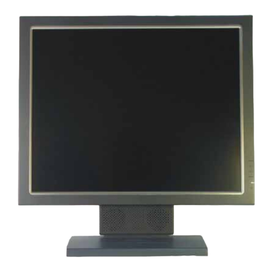
User Manual
SERVICE MANUAL
E
N
9
1
1
0
E
N
9
1
1
0
THESE DOCUMENTS ARE FOR REPAIR SERVICE INFORMATION ONLY. EVERY REASONABLE
EFFORT HAS BEEN MADE TO ENSURE THE ACCURACY OF THIS MANUAL; WE CANNOT
GUARANTEE THE ACCURACY OF THIS INFORMATION AFTER THE DATE OF PUBLICATION AND
DISCLAIMS RE LIABILITY FOR CHANGES, ERRORS OR OMISSIONS.
MANUFACTURE DATA: Jul-29-04
0
Advertisement
Table of Contents
Troubleshooting

Related Manuals for Envision EN9110


Summary of Contents for Envision EN9110
-
Page 1: Service Manual
SERVICE MANUAL THESE DOCUMENTS ARE FOR REPAIR SERVICE INFORMATION ONLY. EVERY REASONABLE EFFORT HAS BEEN MADE TO ENSURE THE ACCURACY OF THIS MANUAL; WE CANNOT GUARANTEE THE ACCURACY OF THIS INFORMATION AFTER THE DATE OF PUBLICATION AND DISCLAIMS RE LIABILITY FOR CHANGES, ERRORS OR OMISSIONS. MANUFACTURE DATA: Jul-29-04... -
Page 2: Table Of Contents
TABLE OF CONTENTS PAGE 1. SPECIFICATIONS FOR LCD MONITOR GENERAL PECIFICATIONS LCD MONITOR DESCRIPTION PANEL SPECIFICATION (AU EN02) 1-3-1 PANEL FEATURE 1-3-2 DISPLAY CHARACTERISTICS 1-3-3 OPTICAL CHARACTERISTICS 1-3-4 PARAMETER GUIDE LINE FOR CCFL INVERTER 1-4 FACTORY PRESET TIMING LIST 1-5 INTERFACE CONNECTOR 2. -
Page 3: Specifications For Lcd Monitor
1. SPECIFICATIONS FOR LCD MONITOR GENARAL SPECIFICATION 1. LCD-Panel: Active display area 19 inch diagonal Pixel pitch 0.294 mm x 0.294 mm Pixel format 1280 x 1024 RGB vertical stripe arrangement 2. Display Color: 8-bit, 16.7 million colors 3. External Controls: Auto Config/Exit, Brightness (up key), contrast (down key), Menu/Enter, Power indicator, Power button 4. -
Page 4: Lcd Monitor Description
LCD MONITOR DESCRIPTION The LCD monitor contains main-board, Inverter module, keyboard, audio module, USB-hub module and External Adapter. The main-board controls all logic signals such as panel control logic, backlight control logic, …etc. The Inverter module will drive the backlight of panel. The Adapter supplies power to the LCD monitor. -
Page 5: Panel Specification (Au En02)
1-3 PANEL SPECIFICATION (AU EN02) 1-3-1 Panel Feature - 19 inch Color TFT-LCD - ALL input signals are 2 Channel LVDS interface compatible - Supported the SXGA(H1280Pixel × V1024Lines) resolution - By applying 16.7M colors (RGB 8 bit data) 1-3-2 Display Characteristics ITEM UNIT SPECIFICATIONS... -
Page 6: Optical Characteristics
1-3-3 Optical Characteristics The optical characteristics are measured under stable conditions at 25℃ (Room Temperature): ITEM UNIT CONDITIONS TYP. MAX. [degree] Horizontal (Right) – CR=10(Left) – [degree] Viewing Angle [degree] Vertical (Up) – CR=10(Down) – [degree] Contrast ratio Normal Direction [m sec] Raising Time –... -
Page 7: Factory Preset Timing List
INVERTER MIN BRINGTHNESS (Vadj:0.0v), LOAD=100KΩX4(ROOM TEMPERATURE 25℃ ±4℃) ITEM SYMBOL MIN. TYP. MAX. UNIT REMARK input voltage 10.8 13.2 input current FOR 4 LOAD Output Current Iout FOR 1 LOAD Frequency FOR 1 LOAD 45.0 50.0 55.0 H.V open Vopen 1550 1700 1850... -
Page 8: Interface Connector
IBM MODES Horizontal Vertical Nominal Nominal Sync Nominal Sync Pixel Mode Resolution Total Frequency Polari Freq. Polarit Clock +/- 0.5kHz +/- 1 Hz (MHz) 720x400@70Hz 900 x 449 31.469 70.087 28.322 720x400@85Hz 936 x 446 37.927 85.039 35.550 640x400@70Hz 800 x 449 31.469 70.087 25.175... -
Page 9: Precaution And Notices
2. PRECAUTIONS AND NOTICES ASSEMBLY PRECAUTION (1) Please do not press or scratch LCD panel surface with anything hard. And do not soil LCD panel surface by touching with bare hands (Polarizer film, surface of LCD panel is easy to be flawed) In the LCD panel, the gap between two glass plates is kept perfectly even to maintain display characteristic and reliability. -
Page 10: Operating Instructions
3. OPERATING INSTRUCTIONS This procedure gives you instructions for installing and using the LCD monitor display. 1. Position the display on the desired operation and plug–in the power cord into External Adapter AC outlet. Three-wire power cord must be shielded and is provided as a safety precaution as it connects the chassis and cabinet to the electrical conduct ground. - Page 11 3. Connect the 24-pin color display shielded DVI-DVI signal cable to your signal system device and lock both screws on the connector to ensure firm grounding. The connector information is as follow: 15 - Pin Color Display Signal Cable PIN NO. DESCRIPTION PI N NO.
-
Page 12: Adjustment
4. ADJUSTMENT 4-1 ADJUSTMENT CONDITIONS AND PRECAUTIONS Adjustments should be undertaken only on following function: Contras, Brightness, Black level, Phase, Clock, H/V-position, Languages, Color- (C2, C1, User), Auto level, , Languages, Reset, RGB level, input selected, scaling mode - Power Button: When pressed, the monitor enters the off mode, and the LED turns blank. - Page 13 Turn the POWER-button off to on to quit from factory mode (in USER-mode, the OSD window location was placed at the middle of the screen) Press MENU button to activate OSD Menu or make a confirmation on desired function, Press Left/Right button to select the function or done the adjustment.
- Page 14 Contrast Adjust the picture contrast. Brightness Adjust the picture brightness. Input Input Signal source selected (select Analog or Digital input Selected source) Focus Adjust picture Focus. Clock Adjust picture Clock. H- Position Adjust the horizontal position of the picture. V- Position Adjust the vertical position of the picture.
-
Page 15: Block Diagram
BLOCK DIAGRAM 6655-1 SPECIAL FUNCTION WITH PRESS-KEY Press menu button during 2 seconds along with plug-in the DC Power cord: That operation will set the monitor into “Factory- mode”, in Factory mode we can do the White balance adjustment with RS232 .In Factory mode, OSD-screen will locate in left top of screen. -
Page 16: Inverter/Power Board
5-2-2 adapter/inverter 1. ADAPTER: CONVERSION-module to convert AC 110V-240V to 12VDC, with 5 2. INVERTER: CONVERSION-module to convert DC 12V to High-Voltage around 1650V, with frequency 30K-80Khz, 5mA-13mA 5-3 SOFTWARE FLOW CHART POWER-ON START Initial MCU I/O, Interrupt vector & Ram Initial 1.POC (backlight counter) Check Eeprom is empty? 2. - Page 17 Main subroutine loop Main loop start Process Power-saving status (according to below flow-chart result) Check gm5020 IFM status .is change or not. And check Signal cable status (cable not connected or not) ** IFM is the register, which measured the HSYN & Vsyn status Yes, IFM have change Wake-up gm5020 (Because gm5020 was in...
-
Page 18: Maintainability
6.MAINTAINABLITY 6-1. EQUITMENTS AND TOOLS REQUIRED 1.) Voltmeter. 2.) Oscilloscope. 3) Pattern Generator. 4) DDC Tool with a personal computer 5) Alignment Tool. 6) LCD Color Analyzer. 7) Service Manual. 8)User Manual. 6-2 TROUBLE SHOOTING 6-2-1 interface board trouble shooting chart *Use the PC Win 98 white pattern, with some icon on it, and Change the Resolution to 640x480 60 Hz / 31 KHz **NOTICE: The free-running freq. - Page 19 No screen appear DC-Power Part Measured Input DC-voltage (J1)= 12 V? Measured U901 SI-8050 pin4=5V? Measured U904 AIC 1084 pin 2 = 3.3V? Measured U903 AIC1117 pin 2= 3.3V? Check Correspondent component. Measured U902 RT9164 pin 2=2.5v Is there any shortage or cold solder? Measured U905 AIC 1084 pin2=2.5V Yes, all DC level exist Yes, there have OSD show...
- Page 20 PANEL-POWER CIRCUIT Check the PPWR panel power relative circuit, R201, R202, Q201, U203 (pin 5,6,7,8) In normal operation, when LED =green, R223 Check R202 should have response from 0V to 5V Should =0 v, When we switch the power switch from off to on If PPWR no-response when the power switch Turn on and turn off, replace the U600-GM5020 OK, R202 have...
- Page 21 II (a) the screen is abnormal, stuck at white screen, OSD window can’t appear, but keyboard & LED is normal operation. At general, this symptom is cause by missing panel data or panel power, so we must check our wire-harness, which connected to panel or the panel power controller (U203) Check if the Wire harness from CN201 loose? Tighten it.
- Page 22 II. (B) The screen had the Vertical Straight Line, may be stuck in Red, Green or Blue That symptom is cause by bad Panel issue (might be the Source IC from Panel is cold soldered or open looped) so replace the panel and try it. III.ALL SCREEN HAS INTERFERENCES OR NOISE, CAN’T BE FIXED BY AUTO KEY ** NOTE: There are so many kinds of interferences, 1).
-
Page 23: Inverter -Module Trouble Shooting Chart
III There is interferences in DOS mode NOTE: the criteria of doing AUTO-CONFIGURATION: must be a full-size screen, if the screen not full, the auto-configuration will fail. So in DOS mode, just set your “CLOCK” in OSD-MENU to zero or use some EDITOR software which can full fill the whole screen (ex: PE2, HE) and then press “AUTO”... - Page 24 Check C1 (+) =12V Check F1/ D1/Q3/Q4or D2/Q9/Q10 Check ON/OFF signal Check Interface board Check IC1 pin9=12V pin9=12vvoltage of C905(+) Check Q1 or Q2 Check the pin1 of IC1 have saw tooth wave Change IC1 Check MOSFET Q5/Q8 if has the output of square wave. Check Q6/Q7//D3 or Q11/Q12 /D4 Check the resonant wave of pin2 &...
-
Page 25: Keyboard-Module Tuouble Shooting Chart
6-2-3 KeyPad Board module trouble-shooting chart OSD is unstable or not working Connect KeyPad Board Is KeyPad Board connecting normally? Replace Button Switch Is Button Switch normally? Replace KeyPad Board Is KeyPad Board Normally? Check Main Board... - Page 26 Check U502 MCU pin 43,42,41,40,39 at Mechanical stuck, Check! High state (5V)? without press any key Check main board PR505 shortage? Replace Tact-switch SW105 at keyboard if still Press power key and check U502 pin 43 no work replace U302 MCU at main-board and = low (0V)? check MCU relative reset circuit, and crystal Check U502 pin 37 (LED green) will have...
-
Page 27: Mechanical Of Cabinet Front Dis-Assembly
7.MECHANICAL OF CABINET FRONT DIS-ASSEMBLY... -
Page 28: Power System And Consumption Current
8.POWER SYSTEM AND CONSUMPTION CURRENT ADAPTER MODULE INVERTER MODULE Input AC 110V, 60Hz/240V, 50Hz Input DC 12V Output AC 1500V/30K-80KHz Output DC 12V 5A Current 14mA Main board power system SI-8050SD, 12V to 5V (5A SPEC) To CPU, Eeprom, 24c21, control-inverter-on.off, and USB hub 860mA when Cable not connected 841mA when Normal operation... -
Page 29: Schematics
9. MAIN BOARD SCHEMATIC... - Page 30 Sheet 3 Sheet 5 Sheet 6 RED+ DCLK RED+ RED+ DCLK DCLK RED- RED- RED- GREEN+ GREEN+ GREEN+ GREEN- GREEN- GREEN- BLUE+ BLUE+ BLUE+ BLUE- DARED[0..7] BLUE- BLUE- DARED[0..7] DARED[0..7] DAGRN[0..7] DAGRN[0..7] DAGRN[0..7] DABLU[0..7] DABLU[0..7] DABLU[0..7] RXC+ RXC+ RXC+ RXC- DBRED[0..7] RXC- RXC-...
- Page 31 VGA_5V AVDD_3.3 D302 4.MCU BAV70 SOT23B D310 D311 D312 BAV99 BAV99 BAV99 /V_CON (R323---U502.24) SHEET 4.MCU AGND AGND AGND SHEET 4.MCU 5.Gm5020 R302 100R C301 0.01uF C308 R321 R322 VGA_5V RED+ SHEET 5.Gm5020 0.1uF R303 100R C302 0.01uF AGND CN301 RED- (C301---U601.E1) RED- SHEET 5.Gm5020...
- Page 32 +A5V 5.Gm5020 L502 HDATAF[0..3](U502.26,27,28,29---U601.R2,R1,P4,P3) CHOKE C509 C511 C512 HCLK (U502.30---U601.P1) C510 0.1UF 0.1UF 100uF 470uF/16V HFS (U502.31---U601.P2) /IRQ (U502.14---U601.R3) RP503 RP502 RESET_FW (U502.25---R906) 10K(8P4R) C501 C502 10K(8P4R) PWM0 (U601.N1---R527) 22uF 0.1uF PWM1 (U601.M4---R528) RP501 D501 HDATAF[0..3] SHEET 5.Gm5020 C505 HDATAF3 3.Input Connectors 22uF HDATAF2...
- Page 33 DVDD_3.3 DVDD_3.3 DVDD_2.5 DVDD_3.3 C600 C601 C602 C603 C604 C605 C606 C607 C608 C609 C610 C611 C612 C613 C614 C615 C616 C617 C618 U600 0.1uF 0.1uF 0.1uF 0.1uF 0.1uF 0.1uF 0.1uF 0.1uF 0.1uF 0.1uF 220pF 220pF 220pF 220pF 220pF 220pF 220pF 220pF 220pF...
- Page 34 5.Gm5020 L3.3V DARED[0..7] (U601---U201) DAGRN[0..7] (U601---U201) FUJITSU㎝SAMSUNG 逼 抖 ぃ 妓 DABLU[0..7] (U601---U201) A1= EVEN B1=ODD DBRED[0..7] (U601---U201) C204 C205 C206 C203 DBGRN[0..7] (U601---U201) EVEN 0.1uF 0.1uF 0.1uF 0.1uF DBBLU[0..7] (U601---U201) U201 DCLK (U601.G20---U201.31,U202.31) DS90CF383MTD TSSOP56 DHS (U601.F20---U201.27,U202.27) SHEET 5.Gm5020 DARED[0..7] PWRDWN DARED0 DVS (U601.F19---U201.28,U202.28) TXIN0 DARED1 TXE0...
- Page 35 DVDD_3.3 F3.3V L801 BEAD (0) C824 0.1uF 910918 SHEET 5.Gm5020 FSDATA[0..47] F3.3V SHEET 5.Gm5020 FSADDR[0..13] 910918 U801 F3.3V FSADDR0 FSDATA0 FSADDR1 FSDATA1 FSADDR2 FSDATA2 FSADDR3 FSDATA3 C801 C802 C803 C804 C805 C806 C807 5.Gm5020 FSADDR4 FSDATA4 FSADDR5 FSDATA5 22uF 0.1uF 0.1uF...
- Page 36 +12V U901 U902 CN901 LP901 AVDD_2.5 SI-8050SD POWER RT9164-25CG L902 +12V_IN L901 Vout 73L253-127-L C902 C903 C909 C911 C908 C910 C901 C906 C904 C905 0.1uF/16V 0.1uF/16V 0.1uF/16V 0.1uF/16V 100uF/16V 100uF/16V INDUTOR-P 330uF/35V D901 330uF/35V 330uF/35V 0.1uF/16V SMB340 R901 C907 0.1uF/16V 0R(NC) AGND U905...
-
Page 37: Adapter Board Schematics
9.2 Adapter Board SCHEMATICS R922 470/1206/0.5W T901 R923 470/1206/0.5W R925 LED1 PQ26/22.5 472/1206 D904 20A/100V C910 BD901 102/500V/1206 GBU 4A/600V R903 R905 R907 624/1206 204/1206 204/1206 11.12 C905 L903 C904 R906 R908 C911 C912 C920 73A-253-91L C913 C914 R904 152/1KV 204/1206 204/1206 150UF/400V... -
Page 38: Inverter Board Schematics
9.3 Inverter Board SCHEMATICS 150uH 3A/32V SI4431 3.9K 3.9K 150uF 150uF .1uF 22pF/3KV SR24 SST3904 SM02B-BHSS 2SC4762 184/250V DTA144WKA 22pF/3KV 1uF/25V SM02B-BHSS ON/OFF SST3906 2SC4762 470R EPC19 1K(1206) DTC144WKA 105/16V BAV99 33L8009 12EH RLS4148 3.9K 105/50V 4.7K 474/25V 105/50V SI4431 BA9741 104/16V 150uH... -
Page 39: Pcb Layout
10. PCB LAYOUT (MAIN PCB LAYOUT) Keyboard-connector Audio-connector Crystal Inverter-connector DC jack LVDS Connector Panel- Power Gm5020 Contro DDC chip Frame store Panel connector RGB input Crystal USB connector DDC chip... -
Page 40: Edid Content
11. EDID CONTENT DIGITAL FF 00 0C 01 1E 78 BF EF 00 FD 00 112 00 ANALOG 0D 01 BF EF 00 3D 00 C0 51 7C 31 FD 00 112 00... -
Page 41: Bom List
0.009 12L 381 1 RUBBER FOOT 15L5790 1 MAIN FRAME 9SAMSUNG 15L5791 1 VESA BRACKET 26L 800673 1A ENVISION BARCODE LABEL 34L1020 U0 1L REAR COVER 34L1021 U0 1L HANDLE REAR COVER 34L1050AU0 5L VESA COVER 34L1051 U2 L STAND COVER... - Page 42 89L 174L19 2A SIGNAL CABLE 89L1748LAA 1 SIGNAL CABLE 89L402A18N IS POWER CORD 95L8018 30 21 HARNESS M1L 330 4128 SCREW M3X4 M1L 330 6128 SCREW M1L1130 6128 SCREW M1L1740 12128 SCREW Q1L 330 10120 SCREW FOR FP/RC Q1L 930 16120 SCREW (3X16) 705L990KB34005 LCD 后壳...
- Page 43 L901 73L 174 29 L LINE FILITER LITAI L901 73L 174 29 T LINEFILTER L901 73L 174 29 LS LINE FILITER LISHIN L902 73L 174 31 L LINE FILTER L902 73L 174 31 T CHOKE COIL L902 73L 174 31 LS LINE FILTER L903 73L 253 91 H...
- Page 44 C905 65L 1K152 1T6285 1.5NF/1KV Z5F+-10% C905 65L 1K152 1T6921 1.5NF/1KV Z5F+-10% C913 67L 305471 3T 470UF 16V ------- ----------------------- ----------------------- ---------- ------ PARENT NO: ADPC1260ASMT LCD ADAPTER ASS'Y FOR MT ------- ----------------------- ----------------------- ---------- ------ IC902 56L 192 10 LM358D IC901 56L 379 33...
- Page 45 C921 65L0805104 22 0.1UF +-10% 25V X7R 080 C917 65L0805105 12 1UF +-10% 16V X7R C916 65L0805221 21 CHIP 220PF 25V NPO C907 65L0805474 27 CHIP 0.47UF 25V Y5V C908 65L0805474 27 CHIP 0.47UF 25V Y5V C923 65L1206101 71 100PF 500V 1/8W C922 65L1206102 32 CHIP 1000PF/X7R +-5%...
- Page 46 C922 67L 309471 3T 470UF +-20% 16V C925 67L 309471 3T 470UF +-20% 16V C901 67L305L331 6 330UF +-20% 35V C904 67L305L331 6 330UF +-20% 35V C905 67L305L331 6 330UF +-20% 35V LP901 71L 55 28 FERRITE BEAD 7.62*5.08* L901 73L 253127 L CC-010730 L502...
- Page 47 Q901 57L 417 4 PMBS3904/PHILIPS-SMT (04 Q902 57L 417 4 PMBS3904/PHILIPS-SMT (04 RP502 61L 125103 8 CHIP AR 8P4R 10KOHM +-5 RP503 61L 125103 8 CHIP AR 8P4R 10KOHM +-5 RP506 61L 125103 8 CHIP AR 8P4R 10KOHM +-5 RP507 61L 125103 8 CHIP AR 8P4R 10KOHM +-5 RP801...
- Page 48 R320 61L0603101 CHIPR 100 OHM +-5% 1/10 R323 61L0603101 CHIPR 100 OHM +-5% 1/10 R337 61L0603102 CHIPR 1K OHM +-5% 1/10W R521 61L0603102 CHIPR 1K OHM +-5% 1/10W R601 61L0603102 CHIPR 1K OHM +-5% 1/10W JP801 61L0603103 CHIPR 10K OHM +-5% 1/10 JP803 61L0603103 CHIPR 10K OHM +-5% 1/10...
- Page 49 R312 61L0603473 CHIP 47K OHM 1/10W R321 61L0603473 CHIP 47K OHM 1/10W R322 61L0603473 CHIP 47K OHM 1/10W R317 61L0603511 CHIPR 510 OHM+-5% 1/10W R318 61L0603511 CHIPR 510 OHM+-5% 1/10W R522 61L0603621 CHIPR 620 OHM+-5% 1/10W R308 61L0603750 CHIPR 75 OHM+-5% 1/10W R309 61L0603750 CHIPR 75 OHM+-5% 1/10W...
- Page 50 C511 65L0603104 12 0.1UF +-10% 16V X7R C600 65L0603104 12 0.1UF +-10% 16V X7R C601 65L0603104 12 0.1UF +-10% 16V X7R C602 65L0603104 12 0.1UF +-10% 16V X7R C603 65L0603104 12 0.1UF +-10% 16V X7R C604 65L0603104 12 0.1UF +-10% 16V X7R C605 65L0603104 12 0.1UF +-10% 16V X7R...
- Page 51 C649 65L0603104 12 0.1UF +-10% 16V X7R C650 65L0603104 12 0.1UF +-10% 16V X7R C651 65L0603104 12 0.1UF +-10% 16V X7R C652 65L0603104 12 0.1UF +-10% 16V X7R C653 65L0603104 12 0.1UF +-10% 16V X7R C654 65L0603104 12 0.1UF +-10% 16V X7R C655 65L0603104 12 0.1UF +-10% 16V X7R...
- Page 52 C924 65L0603104 12 0.1UF +-10% 16V X7R C503 65L0603220 31 CHIP 22PF 50V NPO C504 65L0603220 31 CHIP 22PF 50V NPO C671 65L0603220 31 CHIP 22PF 50V NPO C672 65L0603220 31 CHIP 22PF 50V NPO C309 65L0603470 31 CHIP 47PF 50V NPO C310 65L0603470 31 CHIP 47PF 50V NPO...
- Page 53 L903 71L 57G601 N CHIP BEAD L904 71L 57G601 N CHIP BEAD L905 71L 57G601 N CHIP BEAD L202 71L 59C121 B FCM1608C-121T03 SMD L203 71L 59C121 B FCM1608C-121T03 SMD L204 71L 59C121 B FCM1608C-121T03 SMD L205 71L 59C121 B FCM1608C-121T03 SMD U502 87L 202 44...
- Page 54 52L6025 11707 绝缘片 52L6025 11708 绝缘片 64L179J1841AT MKT CAP. 0.18UF+-5% 100 64L179J1841AT MKT CAP. 0.18UF+-5% 100 65L 3J2206ET 22PF 5% 3KV TDK 65L 3J2206ET 22PF 5% 3KV TDK 65L 3J2206ET 22PF 5% 3KV TDK 65L 3J2206ET 22PF 5% 3KV TDK 67L215C151 4H LOW ESR 150UF 25V 8*7MM 67L215C151 4H...
- Page 55 61L0603153 CHIPR 15KOHM+-5% 1/10W 61L0603153 CHIPR 15KOHM+-5% 1/10W 61L0603183 CHIP 18K OHM 1/10W 61L0603183 CHIP 18K OHM 1/10W 61L0603221 CHIPR 220 OHM+-5% 1/10W 61L0603221 CHIPR 220 OHM+-5% 1/10W 61L0603392 CHIP 3.9K OHM 1/10W 61L0603392 CHIP 3.9K OHM 1/10W 61L0603392 CHIP 3.9K OHM 1/10W 61L0603392 CHIP 3.9K OHM 1/10W 61L0603471...
- Page 56 65L0603474 17 CHIP CAP.CER 0.47UF -20 65L0603474 17 CHIP CAP.CER 0.47UF -20 65L0805102 32 CHIP 1000P 50VX7R 0805 65L0805104 22 0.1UF +-10% 25V X7R 080 65L0805104 32 CHIP 0.1UF 50V X7R 67L 312229 7 SMD 2.2UF +-20% 50V 93L 6432U MLL4148 SMD 93L 6432U MLL4148 SMD...
- Page 57 SW104 77L 604 1 TO CHIP TACT SW SW105 77L 604 1 TO CHIP TACT SW DP101 81L 14 2 BH BL-HY0G034B-TR 715L 981 1 "L901 19" LCD KEY BOARD ------- ----------------------- ----------------------- ---------- ------ PARENT NO: 705L990KB34005 LCD 后壳 ASS'Y ------- ----------------------- -----------------------...