MSI MS-6728 Manual
Hide thumbs
Also See for MS-6728:
- User manual (88 pages) ,
- User manual (110 pages) ,
- User manual (118 pages)
Table of Contents
Advertisement
Quick Links
Advertisement
Table of Contents

Related Manuals for MSI MS-6728


Summary of Contents for MSI MS-6728
- Page 1 865PE/G Neo3 MS-6728 (v3.X) ATX Mainboard G52-M6728XV...
-
Page 2: Fcc-B Radio Frequency Interference Statement
Notice 2 Shielded interface cables and A.C. power cord, if any, must be used in order to comply with the emission limits. VOIR LA NOTICE D’INSTALLATION AVANT DE RACCORDER AU RESEAU. Micro-Star International MS-6728... -
Page 3: Trademarks
Copyright Notice The material in this document is the intellectual property of MICRO-STAR INTERNATIONAL. We take every care in the preparation of this document, but no guarantee is given as to the correctness of its contents. Our products are under continual improvement and we reserve the right to make changes without notice. -
Page 4: Safety Instructions
Alternatively, please try the following help resources for further guidance. Visit the MSI homepage & FAQ site for technical guide, BIOS updates, driver updates, and other information: http://www.msi.com.tw & http://www.msi. -
Page 5: Table Of Contents
CONTENTS FCC-B Radio Frequency Interference Statement ............ii Copyright Notice ......................iii Trademarks ........................iii Revision History ......................iii Safety Instructions ....................... iv Technical Support ......................iv Chapter 1. Getting Started ..................1-1 Mainboard Specifications ..................1-2 Mainboard Layout ....................1-4 Packing Contents .................... - Page 6 IEEE 1394 Connectors: J1394_1, J1394_2 (Optional) ......2-22 IrDA Infrared Module Header: JIR1 ............2-23 Front Panel Audio Connector: JAUD1 ............2-23 CD-IN Connector: JCD1 ................2-24 Chassis Intrusion Switch Connector: JCI1 ..........2-24 Front USB Connectors: JUSB1 & JUSB2 ..........2-24 Jumpers ......................
- Page 7 WLAN Card Mode ..................4-8 Live Update ......................4-9 MEGA STICK ...................... 4-10 Basic Function ..................4-10 Non-Unicode programs supported ............4-12 Core Center (for Pentium 4 CPU) ..............4-14 Left-wing: Current system status ............4-15 Right-wing: PC hardware status during real time operation ....4-15 Audio Speaker Setting ..................
-
Page 8: Chapter 1. Getting Started
Getting Started Chapter 1. Getting Started Getting Started Thank you for choosing the 865PE/G Neo3 (MS-6728) v3.X ATX ® mainboard. The 865PE/G Neo3 is based on Intel 865PE/G & ICH5/5R chipsets for optimal system efficiency. Designed to fit the advanced Intel ®... -
Page 9: Mainboard Specifications
Pentium 4 Prescott LGA775 processors in LGA775 package. Supports up to Pentium 4 3XX, 5XX, 6XX & P4EE (Intel Pentium 4 Processor with HT Technology Extreme Edition) sequence processor or higher speed. (For the latest information about CPU, please visit http://www.msi.com.tw/program/ products/mainboard/mbd/pro_mbd_cpu_support.php) Chipset ®... - Page 10 Getting Started On-Board Peripherals On-Board Peripherals include: - 1 floppy port supports 1 FDD with 360K, 720K, 1.2M, 1.44M and 2.88Mbytes - 1 serial port COMA - 1 VGA port (for 865G only) - 1 parallel port supports SPP/EPP/ECP mode - 8 USB 2.0 ports (Rear * 4/ Front * 4) - 1 Line-In / Line-Out / Mic-In / Real Speaker Out / Center-Subwoofer Speaker Out / SPDIF Out-Optical audio port...
-
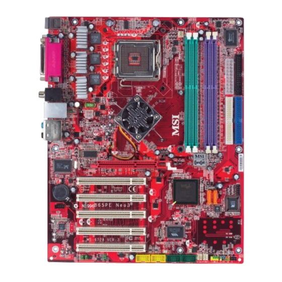
Page 11: Mainboard Layout
PCI Slot 1 JDB1 SATA2 SATA1 ICH5/ PCI Slot 2 BATT ICH5R BIOS PCI Slot 3 JCD1 PCI Slot 4 Codec VT6307 PCI Slot 5 J1394_1 J1394_2 JUSB2 JUSB1 JFP2 JFP1 JIR1 JAUD1 JBAT1 865PE/G Neo3 (MS-6728) v3.X ATX Mainboard... -
Page 12: Packing Contents
Getting Started Packing Contents MSI Driver/Utility CD SATA Cable *2 MSI motherboard D-Bracket 2 Standard Cable for Power Cable (Optional) IDE Devices Standard Cable for User’s Guide Back IO Shield Floppy Disk... -
Page 13: Chapter 2. Hardware Setup
Hardware Setup Chapter 2. Hardware Setup Hardware Setup This chapter tells you how to install the CPU, memory modules, and expansion cards, as well as how to setup the jumpers on the mainboard. Also, it provides the instructions on connecting the peripheral devices, such as the mouse, keyboard, etc. -
Page 14: Quick Components Guide
MS-6728 ATX Mainboard Quick Components Guide CPUFAN1, p.2-15 CPU, p.2-3 DDR DIMMs, p.2-7 JCI1, p.2-23 ATX1, p.2-9 Back Panel I/O, p.2-10 FDD1, p.2-14 JPW1, p.2-9 NBFAN1,p.2-15 IDE1, IDE2, p.2-16 AGP Slot, p.2-26 JDB1, p.2-19 BATT SATA1, SATA2, JCD1, p.2-24 BIOS p.2-17... -
Page 15: Central Processing Unit: Cpu
If you do not have the CPU cooler, contact your dealer to purchase and install them before turning on the computer. For the latest information about CPU, please visit http://www.msi.com.tw/ program/products/mainboard/mbd/pro_mbd_cpu_support.php. MSI Reminds You... -
Page 16: Cpu & Cooler Installation
MS-6728 ATX Mainboard CPU & Cooler Installation When you are installing the CPU, make sure the CPU has a cooler at- tached on the top to prevent overheating. If you do not have the cooler, contact your dealer to purchase and install them before turning on the computer. Meanwhile, do not forget to apply some silicon heat transfer compound on CPU before installing the heat sink/cooler fan for better heat dispersion. - Page 17 Hardware Setup 5. The CPU has a plastic cap on it to 6. Remove the cap from lever hinge side protect the contact from damage. (as the arrow shows). Before you have installed the CPU, always cover it to protect the socket pin.
- Page 18 MS-6728 ATX Mainboard 12. Visually inspect if the CPU is seated 11. Push down the CPU hard to install well into the socket, then remove the the CPU into the socket housing CPU Clip with 2 fingers. Then cover frame.
-
Page 19: Memory
Hardware Setup Memory The mainboard provides 4 slots for 184-pin, 2.5V DDR DIMM with 8 memory banks. You can install DDR266 / DDR333 / DDR400 / DDR433 / DDR466 / DDR500 / DDR533 SDRAM modules on the DDR DIMM slots (DIMM 1~4). To operate properly, at least one DIMM module must be installed. -
Page 20: Installing Ddr Modules
MS-6728 ATX Mainboard Please refer to the following table for detailed dual-channel DDR. Other com- bination not listed below will function as single-channel DDR. DIMM1 (Ch A) DIMM2 (Ch A) DIMM3 (Ch B) DIMM4 (Ch B) System Density 128MB~1GB 128MB~1GB... -
Page 21: Power Supply
JPW1 Pin Definition JPW1 SIGNAL MSI Reminds You... 1. These two connectors connect to the ATX power supply and have to work together to ensure stable operation of the mainboard. 2. Power supply of 350 watts (and above) is highly recommended for system stability. -
Page 22: Back Panel
MS-6728 ATX Mainboard Back Panel The back panel provides the following connectors: RS-Out L-In Parallel S/PDIF Mouse VGA port USB Ports CS-Out COM A L-Out Keyboard (Optional) SPDIF Out Mouse/Keyboard Connector ® The mainboard provides a standard PS/2 mouse/keyboard mini DIN connec- tor for attaching a PS/2 ®... -
Page 23: Vga Connector (Optional)
Hardware Setup VGA Connector (Optional, for 865G only) The mainboard provides a DB 15-pin female connector to connect a VGA monitor. Signal Description Pin Signal Description GREEN BLUE VGA Connector Horizontal Sync Vertical Sync (DB 15-pin) USB Connectors The mainboard provides an OHCI (Open Host Controller Interface) Universal Serial Bus root for attaching USB devices such as keyboard, mouse or other USB- compatible devices. -
Page 24: Serial Port Connector
MS-6728 ATX Mainboard Serial Port Connector The mainboard offers one 9-pin male DIN connector as the serial port. The port is a 16550A high speed communication port that sends/receives 16 bytes FIFOs. You can attach a serial mouse or other serial devices directly to the connector. -
Page 25: Rj-45 Lan Jack
Hardware Setup RJ-45 LAN Jack: 10/100 LAN (8100C) /Giga-bit LAN (8110S) (Optional) The mainboard provides two standard RJ-45 jacks for connection to Local Area Network (LAN). Giga-bit LAN enables data to be transferred at 1000, 100 or 10Mbps. You can connect a network cable to either LAN jack. Activity Indicator Link Indicator RJ-45 LAN Jack... -
Page 26: Parallel Port Connector: Lpt1
MS-6728 ATX Mainboard Parallel Port Connector: LPT1 The mainboard provides a 25-pin female centronic connector as LPT. A parallel port is a standard printer port that supports Enhanced Parallel Port (EPP) and Extended Capabilities Parallel Port (ECP) mode. Pin Definition... -
Page 27: Connectors
Control SFAN1, SFAN2 NBFAN1 CPUFAN1 MSI Reminds You... 1. Always consult the vendors for proper CPU cooling fan. 2. CPUFAN1 supports the fan control. Fan/heatsink with 3 or 4 pins are both available. 3. Please refer to the recommended CPU fans at Intel ®... -
Page 28: Ata100 Hard Disk Connectors: Ide1, Ide2
MS-6728 ATX Mainboard ATA100 Hard Disk Connectors: IDE1 & IDE2 The mainboard has a 32-bit Enhanced PCI IDE and Ultra DMA 66/100 controller that provides PIO mode 0~4, Bus Master, and Ultra DMA 66/100 function. You can connect up to four hard disk drives, CD-ROM and other IDE devices. -
Page 29: Serial Ata/Serial Ata Raid Connectors Controlled By
Take out the dust cover and connect to the hard disk devices Connect to serial ATA ports MSI Reminds You... Please do not fold the serial ATA cable in a 90-degree angle, for this might cause the loss of data during the transmission. 2-17... -
Page 30: Front Panel Connectors: Jfp1 & Jfp2
MS-6728 ATX Mainboard Front Panel Connectors: JFP1 & JFP2 The mainboard provides two front panel connectors for electrical connection ® to the front panel switches and LEDs. JFP1 is compliant with Intel Front Panel I/O Connectivity Design Guide. Power Reset... -
Page 31: D-Bracket Tm 2 Connector: Jdb1
Hardware Setup D-Bracket™ 2 Connector: JDB1 The mainboard comes with a JDB1 connector for you to connect to D- Bracket™ 2, which supports both USB 1.1 & 2.0 spec. D-Bracket™ 2 is a USB bracket integrating four Diagnostic LEDs, which use graphic signal display to help users understand their system. - Page 32 MS-6728 ATX Mainboard D-Bracket™ 2 Green D-Bracket™ 2 Description System Power ON - The D-LED will hang here if the processor is damaged or not installed properly. Early Chipset Initialization Memory Detection Test - Testing onboard memory size. The D-LED will hang if the memory module is damaged or not installed properly.
- Page 33 Hardware Setup D-Bracket™ 2 Description Processor Initialization - This will show information regarding the processor (like brand name, system bus, etc…) Testing RTC (Real Time Clock) Initializing Video Interface - This will start detecting CPU clock, checking type of video onboard.
-
Page 34: Ieee 1394 Connectors: J1394_1, J1394_2 (Optional)
MS-6728 ATX Mainboard IEEE 1394 Connectors: J1394_1, J1394_2 (Optional) The mainboard provides two 1394 pin headers that allow you to connect IEEE 1394 ports via an external IEEE1394 bracket. Pin Definition SIGNAL SIGNAL TPA+ TPA- Ground Ground TPB+ TPB- J1394_1, J394_2... -
Page 35: Irda Infrared Module Header: Jir1
Left channel audio signal to front panel AUD_RET_L Left channel audio signal return from front panel MSI Reminds You... If you don’t want to connect to the front audio header, pins 5 & 6, 9 & 10 have to be jumpered in order to have signal output directed to the rear audio ports. -
Page 36: Cd-In Connector: Jcd1
MS-6728 ATX Mainboard CD-In Connector: JCD1 The connector is for CD-ROM audio connector. JCD1 GND L Chassis Intrusion Switch Connector: JCI1 This connector is connected to a 2-pin chassis switch. If the chassis is opened, the switch will be short. The system will record this status and show a warning message on the screen. -
Page 37: Jumpers
JBAT1 Keep Data Clear Data MSI Reminds You... You can clear CMOS by shorting 2-3 pin while the system is off. Then return to 1-2 pin position. Avoid clearing the CMOS while the system is on; it will damage the mainboard. -
Page 38: Slots
MS-6728 ATX Mainboard Slots The mainboard provides one AGP slot and five 32-bit PCI bus slots. AGP (Accelerated Graphics Port) Slot The AGP slot allows you to insert the AGP graphics card. AGP is an interface specification designed for the throughput demands of 3D graphics. It introduces a 66MHz, 32-bit channel for the graphics controller to directly access main memory. -
Page 39: Chapter 3. Bios Setup
SETUP. You want to change the default settings for customized features. MSI Reminds You... 1. The items under each BIOS category described in this chapter are under continuous update for better system performance. Therefore, the description may be slightly different from the latest BIOS and should be held for reference only. -
Page 40: Entering Setup
MS-6728 ATX Mainboard Entering Setup Power on the computer and the system will start POST (Power On Self Test) process. When the message below appears on the screen, press <DEL> key to enter Setup. DEL: Setup F11: Boot Menu F12: Network boot... -
Page 41: Control Keys
BIOS Setup Control Keys <↑> Move to the previous item <↓> Move to the next item <←> Move to the item in the left hand <→> Move to the item in the right hand <Enter> Select the item Jumps to the Exit menu or returns to the main menu from a <Esc>... -
Page 42: The Main Menu
MS-6728 ATX Mainboard The Main Menu Once you enter AMIBIOS NEW SETUP UTILITY, the Main Menu will appear on the screen. The Main Menu displays some main functions and two exit choices. Use arrow keys to move among the items and press <Enter> to enter the sub-menu. - Page 43 BIOS Setup PC Health Status This entry shows your PC health status. Frequency/Voltage Control Use this menu to specify your settings for frequency/voltage control. Set Supervisor Password Use this menu to set Supervisor Password. Set User Password Use this menu to set User Password. Load High Performance Defaults Use this menu to load the BIOS values for the best system performance, but the system stability may be affected.
-
Page 44: Standard Cmos Features
MS-6728 ATX Mainboard Standard CMOS Features The items inside STANDARD CMOS SETUP menu provide some category, in which include none, one or more setup items. Use the arrow keys to highlight the item you want to modify and use the <PgUp> or <PgDn> keys to switch to the value you prefer. - Page 45 BIOS Setup Heads Enter head number Write Precompensation Enter write precomp cylinder Sectors Enter sector number Maximum Capacity Read the maximal HDD capacity LBA Mode Select [Auto] for a hard disk > 512 MB under Windows and DOS, or [Disabled] under Netware and UNIX Block Mode Select [Auto] to enhance the hard disk performance Fast Programmed I/O Modes...
-
Page 46: Advanced Bios Features
MS-6728 ATX Mainboard Advanced BIOS Features Quick Boot Setting the item to [Enabled] allows the system to boot within 5 seconds since it will skip some check items. Available options: [Enabled], [Disabled]. Boot Device Select Press <Enter> to enter the sub-menu screen. - Page 47 BIOS Setup Full Screen LOGO Show This item enables you to show the company logo on the bootup screen. Settings are: [Enabled] Shows a still image (logo) on the full screen at boot. [Disabled] Shows the POST messages at boot. S.M.A.R.T.
- Page 48 MS-6728 ATX Mainboard Hyper Threading Function This field is used to enable or disable the Hyper Threading function. Setting to [Enabled] will increase the system performance. Settings: [Enabled], [Disabled]. MSI Reminds You... Enabling the functionality of Hyper-Threading Technology for your com- puter system requires ALL of the following platform Components: ®...
- Page 49 BIOS Setup Option Description Disabled The specified ROM is not copied to RAM. Enabled The contents of specified ROM are copied to RAM for faster system performance. Cached The contents of specified ROM are not only copied to RAM, the contents of the ROM area can be written to and read from cache memory.
-
Page 50: Advanced Chipset Features
MS-6728 ATX Mainboard Advanced Chipset Features MSI Reminds You... Change these settings only if you are familiar with the chipset. DRAM Timing Setting... Press <Enter> and to enter the sub-menu screen. Configure SDRAM Timing by SPD Selects whether DRAM timing is controlled by the SPD (Serial Presence Detect) EEPROM on the DRAM module. - Page 51 BIOS Setup RAS# Precharge This item controls the number of cycles for Row Address Strobe (RAS) to be allowed to precharge. If insufficient time is allowed for the RAS to accumulate its charge before DRAM refresh, refreshing may be incomplete and DRAM may fail to retain data.
-
Page 52: Power Management Features
MS-6728 ATX Mainboard Power Management Features ACPI Standby State This item specifies the power saving modes for ACPI function. If your operating system supports ACPI, such as Windows 98SE, Windows ME, Windows 2000 and Windows XP, you can choose to enter the Standby mode in S1(POS) or S3(STR) fashion through the setting of this field. - Page 53 BIOS Setup Suspend Time Out (Minute) After the selected period of system inactivity, all devices except the CPU shut off. Settings: [Disabled], [1], [2], [4], [8], [10], [20], [30], [40], [50], [60]. Power Button Function This feature sets the function of the power button. Settings are: [On/Off] The power button functions as normal power off button.
- Page 54 MS-6728 ATX Mainboard USB Device Wakeup From S3 This item allows the activity of the USB devices (keyboard and mouse) to wake up the system from S3 sleep state. Setting: [Enabled], [Disabled]. Resume On PME# This field specifies whether the system will be awakened from power saving modes when activity or input signal of the specified hardware peripheral or component is detected.
-
Page 55: Pnp/Pci Configurations
BIOS Setup PNP/PCI Configurations This section describes configuring the PCI bus system and PnP (Plug & Play) feature. PCI, or Peripheral Component Interconnect, is a system which allows I/O devices to operate at speeds nearing the speed the CPU itself uses when communicating with its special components. - Page 56 MS-6728 ATX Mainboard [AGP/PCI] The system initializes the installed AGP card first. If an AGP card is not available, it will initialize the PCI VGA card. [PCI/AGP] The system initializes the installed PCI VGA card first. If a PCI VGA card is not available, it will initialize the AGP card.
- Page 57 BIOS Setup Set DMAs to PnP or ISA Press <Enter> to enter the sub-menu and the following screen appears: DMA Channel 0/1/3/5/6/7 These items specify the bus that the system DMA (Direct Memory Access) channel is using. The settings determine if AMIBIOS should remove a DMA from the available DMAs passed to devices that are configurable by the system BIOS.
-
Page 58: Integrated Peripherals
MS-6728 ATX Mainboard Integrated Peripherals Please note that the options showed on your BIOS might be different depending on the motherboard you buy. USB Controller This setting is used to enable/disable the onboard USB host controller. Setting options: [Disabled], [Enabled]. - Page 59 S-ATA Ports Definition This allows you to set the boot sequence of serial ATA ports. MSI Reminds You... If you wish to use S-ATA devices on your mainboard while the ATA devices connected to the IDE1 and IDE2 are also available, you MUST...
- Page 60 MS-6728 ATX Mainboard On-Chip IDE Settings in Windows XP/2000 Settings in Windows 98/ME Configuration (Maximum of 6 devices) (Maximum of 4 devices) On-Chip ATA(s) Legacy Mode (not available) Operate Mode ATA Configuration P-ATA Only P-ATA+S-ATA S-ATA Keep Enabled (not available)
- Page 61 BIOS Setup OnBoard FDC Select [Enabled] if your system has a floppy disk controller (FDD) installed on the system board and you wish to use it. Option Description [Auto] BIOS will automatically determine whether to enable the onboard Floppy controller or not. [Enabled] Enables the onboard Floppy controller.
- Page 62 MS-6728 ATX Mainboard Parallel Port DMA Channel This feature needs to be configured only when Parallel Port Mode is set to the [ECP]. When Parallel Port Mode is set to [Normal], this field will show [Auto] indicat- ing that BIOS automatically determines the DMA channel for the parallel port.
-
Page 63: Pc Health Status
BIOS Setup PC Health Status This section shows the status of your CPU, fan, overall system status, etc. Monitor function is available only if there is hardware monitoring mechanism onboard. Chassis Intrusion The field enables or disables the feature of recording the chassis intrusion status and issuing a warning message if the chassis is once opened. -
Page 64: Frequency/Voltage Control
MS-6728 ATX Mainboard Frequency/Voltage Control Use this menu to specify your settings for frequency/voltage control. Performance Mode This item allows you to control the MAT (memory acceleration technology) function of CPU. MAT is MSI ’s exclusive technology, specializing in optimizing the data transfer rate among CPU, north bridge chip and memory, and also in procuring better memory performance and bandwidth up to 10%. - Page 65 BIOS Setup D.O.T. Range (D.O.T) Dynamic Overclocking Technology is the automatic overclocking function, included in the MSI ’s newly developed CoreCell Technology. It is designed to detect the load balance of CPU while running programs, and to adjust the best CPU frequency automatically.
- Page 66 MS-6728 ATX Mainboard Spread Spectrum When the motherboard’s clock generator pulses, the extreme values (spikes) of the pulses creates EMI (Electromagnetic Interference). The Spread Spectrum function reduces the EMI generated by modulating the pulses so that the spikes of the pulses are reduced to flatter curves.
-
Page 67: Set Supervisor/User Password
If the PASSWORD CHECK option is set to [Always], the password is required both at boot and at entry to Setup. If set to [Setup], password prompt only occurs when you try to enter Setup. MSI Reminds You... About Supervisor Password & User Password: Supervisor password: Can enter and change the settings of the setup menu. -
Page 68: Load High Performance/Bios Setup Defaults
MS-6728 ATX Mainboard Load High Performance/BIOS Setup Defaults The two options on the main menu allow users to restore all of the BIOS settings to High Performance defaults or BIOS Setup defaults. The High Performance Defaults are the values set by the mainboard manufacturer for the best system performance but probably will cause a stability issue. -
Page 69: Chapter 4. Introduction To Digicell
Chapter 2. Hardware Setup Introduction to DigiCell DigiCell, the most useful and powerful utility that MSI has spent much research and efforts to develop, helps users to monitor and configure all the integrated peripherals of the system, such as audio program, power management, MP3 files management and communication / 802.11g WLAN... -
Page 70: Main
Introduction: Click on each icon appearing above to enter the sub-menu to make further configuration. Click on this button to link to MSI website: http://www.msi.com.tw. Quick Guide Click on this button and the quick guide of DigiCell will be displayed for you to review. - Page 71 Power on Agent In this sub-menu, you can configure date, time and auto-executed programs of the power-on, power-off and restarting features. MSI Reminds You... Click on back button in every sub-menu and it will bring you back to the main menu.
-
Page 72: H/W Diagnostic
In the H/W Diagnostic sub-menu, you can see the information, status and note of each DigiCell. You may double check the connection and installation of the item marked as gray. You may also click on the Mail to MSI button to send your questions or suggestions to MSI’s technical support staff. -
Page 73: Communication
Introduction to DigiCell Communication In the Communication sub-menu, you can see the status of all the LAN / WLAN / Bluetooth on the screen if the hardware is installed. The first icon indicates the onboard LAN on your system, the second icon indicates the wireless LAN status, and the third one is the information about the bluetooth on your system. -
Page 74: Software Access Point
MS-6728 ATX Mainboard MSI Feature Software Access Point In the Software Access Point sub-menu, you can see the communication status on your system and choose the desired software access point mode by clicking on the desired icon, in which the default settings are configured for your usage. The default software access point mode is set to WLAN Card Mode. -
Page 75: Access Point Mode
Introduction to DigiCell Access Point Mode Click on “Setting” button of the Access Point Mode and the following screen will display. IP Sharing Click on this icon to enable/disable the IP sharing. The default of this setting is disabled. Disabled. Enabled. -
Page 76: Wlan Card Mode
MS-6728 ATX Mainboard MSI Feature enable this feature, only PCs with MAC address located in Association Control List can connect to the wireless LAN. MAC Address MAC stands for Media Access Control. A MAC address is the hardware address of a device connected to a network. -
Page 77: Live Update
BIOS/VGA Driver/OSD/Utility online so that you don’t need to search for the correct BIOS/driver version throughout the whole Web site. To use the function, you need to install the “MSI Live Update 3” application. After the installation, the “MSI Live Update 3”... -
Page 78: Mega Stick
MS-6728 ATX Mainboard MSI Feature MEGA STICK In the MEGA STICK sub-menu, you can configure the settings of MSI MEGA STICK and the media files (*.m3u, *.mp3, *.wav, *.cda, *.wma) on your system. Basic Function Here you can edit your own play list with the buttons “load”, “save”, “delete”, “shuttle”, “repeat”... - Page 79 Introduction to DigiCell There is also a toolbar for you to execute some basic function, like play, stop, pause, previous/next song, song info and volume adjust. There is also a scroll bar on the top for you to forward/rewind. pause previous next forward/rewind...
-
Page 80: Non-Unicode Programs Supported
MS-6728 ATX Mainboard MSI Feature Non-Unicode programs supported If you are using an operating system in European languages, and you’d like to play the media files in MEGA STICK with East-Asian languages (such as Chinese, Japanese... etc.), it is possible that the file names display incorrectly. - Page 81 Introduction to DigiCell 3. Then go to the [Advanced] tab and select the language you want to be supported (the language of the filename in the MegaStick) from the drop- down list in the [Language for non-Unicode programs], then click [Apply]. The system will install the necessary components from your Microsoft Setup CD immediately.
-
Page 82: Core Center (For Pentium 4 Cpu)
MS-6728 ATX Mainboard MSI Feature Core Center (for Pentium 4 CPU) Click on the Core Center icon in the main menu and the Core Center program will be enabled. CoreCenter is just like your PC doctor that can detect, view and adjust the PC hardware and system status during real time operation. -
Page 83: Left-Wing: Current System Status
Introduction to DigiCell Left-wing: Current system status In the left sub-menu, you can configure the settings of FSB, Vcore, Memory Voltage and AGP Voltage by clicking the radio button next to each item and make it available (the radio button will be lighted as yellow when selected), use the “+” and “-” buttons to adjust, then click “OK”... -
Page 84: Audio Speaker Setting
MS-6728 ATX Mainboard MSI Feature Audio Speaker Setting In the Audio Speaker Setting sub-menu, you can configure the multi-channel audio operation, perform speaker test, and choose the environment you prefer while en- joying the music. You can scroll the bar of each equalizer to regulate the current playing digital sound source. - Page 85 Introduction to DigiCell Click on the “Speaker test” button and the following dialogue box will appear: In this Speaker Configuration dialogue box, select the audio configuration which is identical to the audio jack on your mainboard. Once the correct audio configuration is selected, click “Apply”...
-
Page 86: Power On Agent
MS-6728 ATX Mainboard MSI Feature Power on Agent In the Power on Agent sub-menu, you can configure setting of power-on, power- off and restarting status. In the screen below, you can set the date, time, start-up programs respectively for power-on, power-off and restarting. -
Page 87: Power Off / Restart
Delete. delete the added program MSI Reminds You... You can also enable the Every turn on function, which will enable the specified program(s) and file(s) every time the Digi Cell utility runs. -
Page 88: Auto Login
MS-6728 ATX Mainboard MSI Feature Auto Login Since the Power On function allows the system to power on automatically, you may have to enable this Auto Login function in the following situations: 1. If you are using a computer belonging to a domain in office, and you need to enter your user name &... -
Page 89: Chapter 5. Introdction To Intel Ich65 Serial Ata Raid
1. Supports 150 MB/s transfers with CRC error checking 2. Data handling optimizations including tagged command queuing, elevator seek and packet chain command MSI Reminds You... All the information/volumes listed in your system might differ from the illustrations in this appendix. -
Page 90: Introduction
MS-6728 ATX Mainboard Introduction Following are the Parallel ATA (P-ATA) and Serial ATA (S-ATA) device configu- rations supported by Intel ICH5R. ATA Operate Mode There are two modes to select: Legacy mode and Native mode. Legacy Mode: --- In this mode, system BIOS just assign the traditional 14 and 15 IRQs to use for HDD. - Page 91 Introduction to Intel ICH5R Serial ATA RAID What is RAID 0 (striping)? RAID 0 leverages the read/write capabilities of two or more hard drives working in unison to maximize the storage performance of a computer system. Data in a RAID 0 volume is arranged into blocks that are interleaved among the disks so that reads and writes can be performed in parallel (see below diagram).
- Page 92 MS-6728 ATX Mainboard What is RAID 1 (mirroring)? A RAID 1 array contains two hard drives where the data between the two is mirrored in real time. Since all of the data is duplicated, the operating system treats the usable space of a RAID 1 array as the maximum size of one hard drive in the array.
-
Page 93: Bios Configuration
Intel RAID Option ROM. During the Power-On Self Test (POST), the following message will appear for a few seconds: MSI Reminds You... The “Driver Model”, “Serial #” and “Size” in the following example might be different from your system. - Page 94 MS-6728 ATX Mainboard 2. Creating, Deleting and Resetting RAID Volumes: After pressing the <Ctrl> and <I> keys simultaneously, the following window will appear: (1) Create RAID Volume 1. Select option 1 “Create RAID Volume” and press <Enter> key. The following screen appears: MSI Reminds You...
- Page 95 Introduction to Intel ICH5R Serial ATA RAID 2. Specify a RAID Volume name and then press the <TAB> or <Enter> key to go to the next field. 3. Select the strip value for the RAID 0 or RAID 1 array by using the “upper arrow” or “down arrow”...
- Page 96 MS-6728 ATX Mainboard 4. From the Strip size, press the <Tab> or <ENTER> key to advance to the Create Volume prompt. The window will appear as follows: 5. Then press <Enter> to create the specified volume and the following prompt will...
- Page 97 Introduction to Intel ICH5R Serial ATA RAID 6. Press <Y> to confirm the selection or press <N> to create the RAID volume again. Then you will return to the main menu with an updated status as follows: 7. Scroll to option 4 Exit and press <Enter> to exit the RAID Configuration utility. The following prompt appears: 8.
- Page 98 MS-6728 ATX Mainboard (2) Delete RAID Volume Here you can delete the RAID volume, but please be noted that all data on RAID drives will be lost. MSI Reminds You... If your system currently boots to RAID and you delete the RAID volume in the Intel RAID Option ROM, your system will become unbootable.
- Page 99 Introduction to Intel ICH5R Serial ATA RAID Select the volume and press <Delete> key to delete the RAID volume. The following prompt appears: Press <Y> key to accept the volume deletion. 5-11...
- Page 100 MS-6728 ATX Mainboard (3) Reset Disks to Non-RAID Select option 3 Reset Disks to Non-RAID and press <Enter> to delete the RAID volume and remove any RAID structures from the drives. The following screen appears: Press <Y> key to accept the selection.
-
Page 101: Installing Software
Windows XP installation. Existing Windows XP / 2000 Driver Installation 1. Insert the MSI CD into the CD-ROM drive. 2. The CD will auto-run and the setup screen will appear. 3. Under the Driver tab, click on Intel IAA RAID Edition. -
Page 102: Installation Of Intel Application Accelerator Raid Edition
Intel Application Accelerator RAID Edition utility Help documentation Start menu shortcuts and system tray icon service RAID Monitor service Insert the MSI CD and click on the Intel IAA RAID Edition to install the software. Click the Intel IAA RAID Edition 5-14... - Page 103 Introduction to Intel ICH5R Serial ATA RAID The InstallShield Wizard will begin automatically for installation showed as following: Click on the Next button to proceed the installation in the welcoming window. 5-15...
- Page 104 MS-6728 ATX Mainboard The window shows the components to be installed. Click Next button to continue. After reading the license agreement in the following window, click Yes button to continue. 5-16...
- Page 105 Introduction to Intel ICH5R Serial ATA RAID Select the folder in which you want the program to be installed in the following window, and click Next button to start installation. Select a program folder in the following window where you want Setup to add the program icon.
- Page 106 MS-6728 ATX Mainboard The following window appears to show the Intel Application Accelerator RAID Edition Setup installation status. Once the installation is complete, the following window appears. 5-18...
-
Page 107: Raid Migration Instructions
To create a volume from an existing disk, complete the following steps: MSI Reminds You... A Create from Existing Disk operation will delete all existing data from the added disk and the data cannot be recovered. It is critical to backup all important data on the added disk before proceeding. -
Page 108: Create Raid Volume From Existing Disk
MS-6728 ATX Mainboard Create RAID Volume from Existing Disk To create a RAID volume from an existing disk, right-mouse click on RAID Volume and select Create From Existing Disk to create a new RAID volume as the screen below. You may also use the RAID drop-down menu and click on Create Volume from Existing Disk. - Page 109 Introduction to Intel ICH5R Serial ATA RAID (2) Step 2 of 3: Select the RAID Volume Name and Strip Size In Step 2, select the RAID volume name and strip size, and click Next: RAID Volume Name: A desired RAID volume name needs to be typed in where the ‘RAID_Volume1’ text currently appears above.
- Page 110 MS-6728 ATX Mainboard Before you continue to Step 3 of 3 by clicking Next in Step 2 of 3, read the next 2 dialogue boxes carefully. Please note that once you have selected Migrate on Step 3 of 3, the Intel Application Accelerator RAID Edition will have claimed the disks to be used in creating a new volume and this operation cannot be undone.
- Page 111 Introduction to Intel ICH5R Serial ATA RAID Migration Process The migration process may take up to two hours to complete depending on the size of the disks being used and the strip size selected. A dialog window will appear stating that the migration process may take considerable time to complete and you must click Yes in order to start the migration.
-
Page 112: Chapter 6. Introduction To Realtek Alc850
Introduction to Realtek ALC 850 Chapter 5. Intel ICH6R RAID Introduction Introduction to Realtek ALC850 The mainboard is equipped with Realtek ALC850 chip, which provides sup- port for 8-channel audio output, including 2 Front, 2 Rear, 1 Center and 1 Subwoofer channel. -
Page 113: Installing The Audio Driver
MS-6728 ATX Mainboard Installing the Audio Driver You need to install the driver for Realtek ALC850 codec to function properly before you can get access to 2-, 4-, 6- or 8- channel audio operations. Follow the proce- dures described below to install the drivers for different operating systems. - Page 114 Introduction to Realtek ALC 850 3. Click Next to install the AC’97 Audio software. Click here 4. Click Finish to restart the system. Select this option Click here 6 - 3...
-
Page 115: Software Configuration
MS-6728 ATX Mainboard Software Configuration After installing the audio driver, you are able to use the 2-, 4-, 6- or 8- channel audio feature now. Click the audio icon from the system tray at the lower-right corner of the screen to activate the AC97 Audio Configuration. It is also available to enable the audio driver by clicking the Sound Effect Manager from the Control Panel. -
Page 116: Sound Effect
Introduction to Realtek ALC 850 Sound Effect Here you can select a sound effect you like from the Environment list. Edit You may also edit the properties for an environment as you wish by clicking the “Edit” button, then just scroll the bar in the bottom for each property to adjust. 6 - 5... - Page 117 MS-6728 ATX Mainboard You may choose the provided sound effects, and the equalizer will adjust automatically. If you like, you may also load an equalizer setting or make an new equalizer setting to save as an new one by using the “Load EQ Setting” and “Save Preset”...
-
Page 118: Speaker Configuration
Introduction to Realtek ALC 850 Speaker Configuration In this tab, you can easily configure your multi-channel audio function and speakers. 1. First you have to select the audio configuration below which is identical to the audio jack on your mainboard. In this model it uses Realtek ALC850 codec which supports 8-channel S/PDIF, therefore you should choose 8CH- S/PDIF (Optical &... - Page 119 MS-6728 ATX Mainboard Select the speaker by clicking it to test its functionality. The one you select will light up and make testing sound. If any speaker fails to make sound, then check whether the cable is inserted firmly to the connector or replace the bad speakers with good ones.
-
Page 120: Hrtf Demo
Introduction to Realtek ALC 850 HRTF Demo In this tab you may adjust your HRTF (Head Related Transfer Functions) 3D positional audio before playing 3D audio applications like gaming. You may also select different environment to choose the most suitable environment you like. 6 - 9... -
Page 121: General
MS-6728 ATX Mainboard General In this tab it provides some information about this AC97 Audio Configuration utility, including Audio Driver Version, DirectX Version, Audio Controller & AC97 Codec. You may also select the language of this utility by choosing from the Language list. -
Page 122: Spdif
Introduction to Realtek ALC 850 SPDIF In this tab it provides options about SPDIF-Out for you to configure. No Output: With this option, there is no S/PDIF output signal while playing analog and digital audio. Output digital only: With this option, only digital audio will be allowed to play via SPDIF out while playing analog and digital audio. -
Page 123: Using 2-, 4-, 6- & 8- Channel Audio Function
MS-6728 ATX Mainboard Using 2-, 4-, 6- & 8- Channel Audio Function Connecting the Speakers When you have set the Multi-Channel Audio Function mode properly in the software utility, connect your speakers to the correct phone jacks in accordance with the setting in software utility. - Page 124 Introduction to Realtek ALC 850 4-Channel Mode for 4-Speaker Output Description: Connect two speakers to back panel’s Line Out connector and two speakers to the real-chan- 4-Channel Analog Audio Output nel Line Out connector. Line In Line Out (Front channels) Line Out (Rear channels) Line Out (Center and Subwoofer channel, but no functioning in this mode) Optical SPDIF jack...
- Page 125 MS-6728 ATX Mainboard 6-Channel Mode for 6-Speaker Output Description: Connect two speakers to back panel’s Line Out connector, two speakers to the rear-channel 6-Channel Analog Audio Output and two speakers to the cen- ter/subwoofer-channel Line Out connectors. Line In Line Out (Front channels)
- Page 126 Introduction to Realtek ALC 850 8-Channel Mode for 8-Speaker Output Description: Connect two speakers to back panel’s Line Out connector, two speakers to the rear-channel, 8-Channel Analog Audio Output two speakers to the center/ subwoofer-channel Line Out connectors, and two speakers Line Out (Side channels) to the side-channel Line Out Line Out (Front channels)