Table of Contents
Advertisement
Advertisement
Table of Contents

Related Manuals for MSI K8T Neo-FSR


Summary of Contents for MSI K8T Neo-FSR
- Page 1 K8T Neo MS-6702 (v1.X) ATX Mainboard Version 1.1 G52-M6702X7...
-
Page 2: Fcc-B Radio Frequency Interference Statement
Manual Rev: 1.0 Release Date: September 2003 FCC-B Radio Frequency Interference Statement This equipment has been tested and found to comply with the limits for a class B digital device, pursuant to part 15 of the FCC rules. These limits are designed to provide reasonable protection against harmful interference when the equip- ment is operated in a commercial environment. -
Page 3: Copyright Notice
Alternatively, please try the following help resources for further guidance. Visit the MSI website for FAQ, technical guide, BIOS updates, driver updates, and other information: http://www.msi.com.tw/ Contact our technical staff at: support@msi.com.tw... -
Page 4: Safety Instructions
Safety Instructions Always read the safety instructions carefully. Keep this User’s Manual for future reference. Keep this equipment away from humidity. Lay this equipment on a reliable flat surface before setting it up. The openings on the enclosure are for air convection hence protects the equipment from overheating. -
Page 5: Table Of Contents
Safety Instructions ... v Chapter 1. Getting Started ... 1-1 Mainboard Specifications ... 1-2 Mainboard Layout ... 1-4 MSI Special Features ... 1-5 Color Management ... 1-5 Core Center ... 1-6 Core Cell™ Chip ... 1-9 Dynamic Overclocking Technology ... 1-10 Live BIOS™/Live Driver™... - Page 6 Back Panel ... 2-13 Mouse Connector ... 2-13 Keyboard Connector ... 2-13 USB 2.0 Connectors ... 2-14 IEEE1394 Ports (Optional) ... 2-14 Serial Port Connector: COM A ... 2-15 RJ-45 LAN Jack (Optional) ... 2-15 Audio Port Connectors ... 2-16 Parallel Port Connector: LPT1 ...
- Page 7 Chapter 3. BIOS Setup ... 3-1 Entering Setup ... 3-2 Selecting the First Boot Device ... 3-2 Control Keys ... 3-3 Getting Help ... 3-3 The Main Menu ... 3-4 Standard CMOS Features ... 3-6 Advanced BIOS Features ... 3-8 Advanced Chipset Features ...
-
Page 8: Chapter 1. Getting Started
Chapter 1. Getting Started Getting Started Thank you for purchasing K8T Neo (MS-6702 v1.X) ATX mainboard. The K8T Neo is based on VIA & VT8237 South Bridge chipsets and provides eight USB 2.0 ports for high-speed data transmission, RealTek ALC655 chip for 6-channel audio output, and a SPDIF interface for digital audio transmission. -
Page 9: Mainboard Specifications
MS-6702 ATX Mainboard Mainboard Specifications Supports 64-bit AMD Athlon64 processor (Socket 754) ® Supports up to 3200+, 3400+, or higher CPU Chipset K8T800 chipset ® - HyperTransport connection to AMD Athlon64 processor - 8 or 16 bit control/address/data transfer both directions - 800/600/400/200 MHz “Double Data Rate”... - Page 10 Promise 20378 On-Board (Optional) Supports 2 serial ATA plus 1 ATA133 - RAID 0, RAID 1 or RAID 0+1 is supported - RAID function work w/ATA133+SATA H/D or 2SATA H/D Connect up to 2 SATA device and 2 ATA133 devices On-Board Peripherals On-Board Peripherals include: - 1 floppy port supports 2 FDDs with 360K, 720K, 1.2M, 1.44M and...
-
Page 11: Mainboard Layout
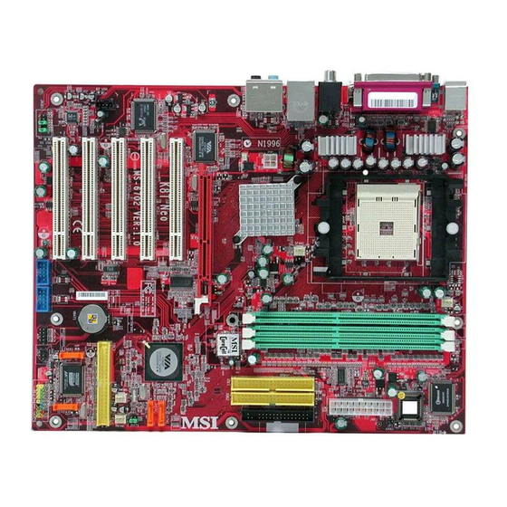
MS-6702 ATX Mainboard Mainboard Layout Top : mouse Bottom: keyboard Top : Parallel P ort Bottom: 1394 port Mini 1394 port T: SPDIF Out B: USB ports Top: LAN jack Bottom: USB ports Line-In Line-Out B:Mic Line-Out JPW1 Line-Out B:SPDIF Out VT6307 PCI Slot 1 PCI Slot 2... -
Page 12: Msi Special Features
MSI Special Features Color Management MSI has a unified color management rule for some connectors on the mainboards, which helps you to install the memory modules, expansion cards and other peripherals devices more easily and conveniently. Memory DDR DIMMs: Light Green... -
Page 13: Core Center
MS-6702 ATX Mainboard Core Center The Core Center is a new utility you can find in the CD-ROM disk. The utility is just like your PC doctor that can detect, view and adjust the PC hardware and system status during real time operation. Cool’n’Quiet This utility provides a CPU temperature detecting function called Cool’n’Quiet. - Page 14 In addition to Cool’n’Quiet setting, the current system status (including Vcore, 3.3V, +5V and 12V) and the current PC hardware status (such as the CPU & system temperatures and all fans speeds) are also shown on the left and right sides. When you click the red triangles in the left and right sides, two sub- menus will open for users to overclock, overspec or to adjust the thresholds of system to send out the warning messages.
- Page 15 MS-6702 ATX Mainboard MSI Reminds You... To ensure that Cool’n’Quiet function is activated and will be working properly, it is required to double confirm that: 1. Check the serial number printed on the top of CPU. On the top of CPU, there are three lines listed under AMD Athlon Find the 13 characters of the first line, and locate the last one from those 13 characters.
-
Page 16: Core Cell™ Chip
Core Cell Chip By diagnosing the current system utilization, the CoreCell™ Chip automatically tunes your motherboard to the optimal state, leading to less noise, longer duration, more power- saving and higher performance. Features of CoreCell™ PowerPro -- Saves up to 65% power. -
Page 17: Dynamic Overclocking Technology
It is designed to detect the load balance of CPU while running programs, and to adjust the best CPU frequency automatically. When the motherboard detects CPU is running programs, it will speed up CPU automatically to make the program run smoothly and faster. When the CPU is temporarily suspending or staying in the low load balance, it will restore the default settings instead. -
Page 18: Live Bios™/Live Driver
Live Update 3” icon (as shown on the right) will appear on the screen. Double click the “MSI Live Update 3” icon, and the following screen will appear: Five buttons are placed on the left column of the screen. Click the desired button to start the update process. -
Page 19: Live Monitor
Live Monitor™ The Live Monitor™ is a tool used to schedule the search for the latest BIOS/drivers version on the MSI Web site. To use the function, you need to install the “MSI Live Update 3” application. After installation, the “MSI Live Monitor” icon (as shown on the right) will appear on the screen. -
Page 20: D-Bracket™ 2 (Optional)
D-Bracket™ 2 (Optional) D-Bracket™ 2 is an external USB bracket integrating four Diagnostic LEDs, which use graphic signal display to help users understand their system. The LEDs provide up to 16 combinations of signals to debug the system. The 4 LEDs can debug all problems that fail the system, such as VGA, RAM or other failures. - Page 21 MS-6702 ATX Mainboard D-Bracket™ 2 Processor Initialization - This will show information regarding the processor (like brand name, system bus, etc...) Testing RTC (Real Time Clock) Initializing Video Interface - This will start detecting CPU clock, checking type of video onboard. Then, detect and initialize the video adapter.
-
Page 22: Chapter 2. Hardware Setup
Chapter 2. Hardware Setup Hardware Setup This chapter tells you how to install the CPU, memory modules, and expansion cards, as well as how to setup the jump- ers on the mainboard. Also, it provides the instructions on con- necting the peripheral devices, such as the mouse, keyboard, etc. -
Page 23: Quick Components Guide
MS-6702 ATX Mainboard Quick Components Guide CPU, p.2-3 Back Panel I/O, p.2-13 JPW1, p.2-12 AGP Slot, p.2-27 PCI Slots, p.2-27 J4, p.2-20 JAUD1, p.2-24 CFAN1, p.2-19 SFAN1, p.2-19 DDR DIMMs, p.2-9 JUSB1, p.2-20 JIR1, p.2-18 JUSB2, p.2-20 JLED, p.2-25 JCASE1, p.2-18 ATX, p.2-12 FDD1, p.2-18 IDE1, IDE2, p.2-21... -
Page 24: Central Processing Unit: Cpu
If you do not have the heat sink and cooling fan, contact your dealer to purchase and install them before turn- ing on the computer. MSI Reminds You... Overheating Overheating will seriously damage the CPU and system, always make sure the cooling fan can work properly to protect the CPU from overheating. -
Page 25: Cpu Installation Procedures For Socket 754
MS-6702 ATX Mainboard CPU Installation Procedures for Socket 754 Please turn off the power and unplug the power cord before installing the CPU. Pull the lever sideways away from the socket. Make sure to raise the lever up to a 90- degree angle. -
Page 26: Installing Amd Athlon64 Cpu Cooler Set
Installing AMD Athlon64 CPU Cooler Set When you are installing the CPU, make sure the CPU has a heat sink and a cooling fan attached on the top to prevent overheating. If you do not have the heat sink and cooling fan, contact your dealer to purchase and in- stall them before turning on the computer. - Page 27 MS-6702 ATX Mainboard 3. Turn over the mainboard again, and place the mainboard on the flat surface. Locate the two screw holes of the mainboard. 4. Align the retention mechanism and the backplate. Fix the retention mechanism and the backplate with two screws.
- Page 28 6. Press down the other end of the clip to fasten the cooling set on the top of the retention mechanism. 7. Locate the Fix Lever, Saftey Hook and the Fixed Bolt. Lift up the intensive fixed lever. Hardware Setup Safety Hook Fixed Lever Fixed Bolt...
- Page 29 9. Make sure the safety hook completely clasps the fixed bolt of the retention mechanism. MSI Reminds You... While disconnecting the Safety Hook from the fixed bolt, it is necessary to keep an eye on your fingers, because once the Safety Hook is disconnected from the fixed bolt, the fixed lever will spring back instantly.
-
Page 30: Memory
3.3 volts used in SDR SDRAM, and requires 184-pin DIMM mod- ules rather than 168-pin DIMM modules used by SDR SDRAM. High memory bandwidth makes DDR an ideal solution for high performance PC, worksta- tions and servers. Memory *Please Refer to <www.msi.com.tw> <www.msi.com.tw> <www.msi.com.tw> <www.msi.com.tw> <www.msi.com.tw>... -
Page 31: Ddr Dimm Module Combination
2. Insert the DIMM memory module vertically into the DIMM slot. Then push it in until the golden finger of the memory module is deeply inserted in the socket. MSI Reminds You... You can barely see the golden finger if the module is properly inserted in the socket. -
Page 32: Recommended Memory Combination List
Recommended Memory Combination List DIMM Slot DIMM1 DIMM2 DIMM3 S: Single Side Max Speed DDR 400 DDR 400 DDR 400 DDR 400 DDR 400 DDR 400 DDR 400 DDR 400 DDR 400 DDR 400 DDR 400 DDR 400 DDR 400 DDR 400 DDR 400 DDR 400... -
Page 33: Power Supply
ATX 12V Power Connector: JPW1 This 12V power connector is used to provide power to the CPU. JPW1 MSI Reminds You... Power supply of 300 (and up) watt is highly recommended for sys- tem stability. 2-12... -
Page 34: Back Panel
The back panel provides the following connectors: Parallel Mouse Keyboard COM A 1394 Port (Optional) Mouse Connector The mainboard provides a standard PS/2 ® for attaching a PS/2 mouse. You can plug a PS/2 connector. Keyboard Connector The mainboard provides a standard PS/2 ®... -
Page 35: Usb 2.0 Connectors
MS-6702 ATX Mainboard USB 2.0 Connectors The mainboard provides a UHCI (Universal Host Controller Interface) Universal Serial Bus root for attaching USB devices such as keyboard, mouse or other USB-compatible devices. You can plug the USB device directly into the connector. USB Ports IEEE1394 Ports (Optional) The mainboard provides two IEEE 1394 ports. -
Page 36: Serial Port Connector: Com A
Serial Port Connector: COM A The mainboard offers one 9-pin male DIN connector as a serial port COM A. The ports are 16550A high speed communication ports that send/ receive 16 bytes FIFOs. You can attach a serial mouse or another serial device directly to the connector. -
Page 37: Audio Port Connectors
6-channel audio operation, please refer to Appendix A: Using 4- or 6- Channel Audio Function. Line In Line Out MSI Reminds You... For advanced audio application, Realtek ALC655 audio chip is provided to offer support for 6-channel audio operation and can turn rear audio connectors from 2-channel to 4-/6-channel audio. -
Page 38: Parallel Port Connector: Lpt1
Parallel Port Connector: LPT1 The mainboard provides a 25-pin female centronic connector as LPT. A parallel port is a standard printer port that supports Enhanced Parallel Port (EPP) and Extended Capabilities Parallel Port (ECP) mode. SIGNAL STROBE DATA0 DATA1 DATA2 DATA3 DATA4 DATA5... -
Page 39: Connectors
MS-6702 ATX Mainboard The mainboard provides connectors to connect to FDD, IDE HDD, case, modem, LAN, USB Ports, IR module and CPU/System/Power Supply FAN. Floppy Disk Drive Connector: FDD1 The mainboard provides a standard floppy disk drive connector that supports 360K, 720K, 1.2M, 1.44M and 2.88M floppy disk types. IrDA Infrared Module Header: JIR1 The connector allows you to connect to IrDA Infrared module. -
Page 40: Fan Power Connectors: Cfan1/Sfan1/Pwfan1/Pwfan2
CPU fan control. +12V SENSOR CFAN1 MSI Reminds You... 1. Always consult the vendors for proper CPU cooling fan. 2. CFAN1 supports the fan control. You can install Core Center utility that will automatically control the CPU fan speed according to the actual CPU temperature. -
Page 41: Front Panel Connectors: Jfp1 & Jfp2
Power JFP2 Speaker MSI Reminds You... If the Power LED on the front panel flashes every two seconds, this signal tells you that one of the power connection has been protected; if the Power LED flashes every one second, it tells that the CUP has been protected due to overheating. -
Page 42: Hard Disk Connectors: Ide1 & Ide2
IDE2 (Secondary IDE Connector) IDE2 can also connect a Master and a Slave drive. MSI Reminds You... If you install two hard disks on cable, you must configure the second drive to Slave mode by setting its jumper. Refer to the hard disk documentation supplied by hard disk vendors for jumper setting instructions. -
Page 43: Ser1, Ser2
MS-6702 ATX Mainboard Serial ATA/Serial ATA RAID Connectors controlled by VT8237: SATA1, SATA2 The Southbridge of this mainboard is VT8237 which supports two serial connectors SATA1 & SATA2. SATA1 & SATA2 are dual high-speed Serial ATA interface ports. Each supports 1 generation serial ATA data rates of 150 MB/s. - Page 44 Optional Serial ATA cable Connect to SER1 / SER2 or SATA1 / SATA2 MSI Reminds You... Please do not fold the serial ATA cable in a 90-degree angle, since this will cause the loss of data during the transmission. Optional Power Cable...
-
Page 45: Front Panel Audio Connectors: Jaud1
AUD_RET_R HP_ON AUD_FPOUT_L AUD_RET_L MSI Reminds You... If you don’t want to connect to the front audio header, pins 5 & 6, 9 & 10 have to be jumpered in order to have signal output directed to the rear audio ports. Otherwise, the Line-Out connector on the back panel will not function. -
Page 46: D-Bracket™ 2 Connector: Jled (Optional)
D-Bracket™ 2 Connector: JLED (Optional) The mainboard comes with a JLED connector for you to connect to D- Bracket™ 2. D-Bracket™ 2 is a USB Bracket that supports both USB1.1 & 2. 0 spec. It integrates four LEDs and allows users to identify system problem through 16 various combinations of LED signals. -
Page 47: Jumper
MS-6702 ATX Mainboard The motherboard provides the following jumper for you to set the computer’s function. This section will explain how to change your motherboard’s function through the use of jumper. Clear CMOS Jumper: JBAT1 There is a CMOS RAM on board that has a power supply from external battery to keep the data of system configuration. -
Page 48: Slots
The motherboard provides one AGP slot, and five 32-bit PCI bus slots. AGP Slot PCI Slots AGP (Accelerated Graphics Port) Slot The AGP slot allows you to insert the AGP graphics card. AGP is an interface specification designed for the throughput demands of 3D graphics. -
Page 49: Pci Interrupt Request Routing
MS-6702 ATX Mainboard PCI Interrupt Request Routing The IRQ, acronym of interrupt request line and pronounced I-R-Q, are hardware lines over which devices can send interrupt signals to the microprocessor. The PCI IRQ pins are typically connected to the PCI bus INT A# ~ INT D# pins as follows: Order 1 PCI Slot 1... -
Page 50: Chapter 3. Bios Setup
Chapter 3. BIOS Setup BIOS Setup This chapter provides information on the BIOS Setup program and allows you to configure the system for optimum use. You may need to run the Setup program when: An error message appears on the screen during the system booting up, and requests you to run SETUP. -
Page 51: Entering Setup
MS-6702 ATX Mainboard Entering Setup Power on the computer and the system will start POST (Power On Self Test) process. When the message below appears on the screen, press <DEL> key to enter Setup. DEL:Setup F11:Boot Menu If the message disappears before you respond and you still wish to enter Setup, restart the system by turning it OFF and On or pressing the RESET button. -
Page 52: Control Keys
Control Keys < > Move to the previous item < > Move to the next item < > Move to the item in the left hand < > Move to the item in the right hand <Enter> Select the item <Esc>... -
Page 53: The Main Menu
MS-6702 ATX Mainboard The Main Menu Once you enter AMIBIOS NEW SETUP UTILITY, the Main Menu will appear on the screen. The Main Menu displays twelve configurable func- tions and two exit choices. Use arrow keys to move among the items and press <Enter>... - Page 54 BIOS Setup PC Health Status This entry shows your PC health status. Frequency/Voltage Control Use this menu to specify your settings for frequency/voltage control. Set Supervisor Password Use this menu to set Supervisor Password. Set User Password Use this menu to set User Password. Load High Performance Defaults Use this menu to load the BIOS values for the best system performance, but the system stability may be affected.
-
Page 55: Standard Cmos Features
MS-6702 ATX Mainboard Standard CMOS Features The items inside STANDARD CMOS SETUP menu are divided into 9 categories. Each category includes none, one or more setup items. Use the arrow keys to highlight the item you want to modify and use the <PgUp> or <PgDn>... - Page 56 When Enabled, BIOS will issue a virus warning message and beep if a write to the boot sector or the partition table of the HDD is attempted. Setting options: Disabled and Enabled. MSI Reminds You... This feature only protects the boot sector, not the whole hard disk.
-
Page 57: Advanced Bios Features
MS-6702 ATX Mainboard Advanced BIOS Features Quick Boot Setting the item to Enabled allows the system to boot within 5 seconds since it will skip some check items. Available options: Enabled, Disabled. Full Screen LOGO Show This item enables you to show the company logo on the bootup screen. Set- tings are: Enabled Shows a still image (logo) on the full screen at boot. - Page 58 porting Technology) capability for the hard disks. S.M.A.R.T is a utility that monitors your disk status to predict hard disk failure. This gives you an op- portunity to move data from a hard disk that is going to fail to a safe place before the hard disk becomes offline.
- Page 59 MS-6702 ATX Mainboard Internal Cache Cache memory is additional memory that is much faster than conventional DRAM (system memory). When the CPU requests data, the system transfers the requested data from the main DRAM into cache memory, for even faster access by the CPU.
-
Page 60: Advanced Chipset Features
Advanced Chipset Features MSI Reminds You... Change these settings only if you are familiar with the chipset. System Performance This item specifies the system performance status. Set to Turbo to enhance the system performance, or set to Fast for regular system performance. Setting options: Fast, Turbo. - Page 61 MS-6702 ATX Mainboard Bank Interleaving This field selects 2-bank or 4-bank interleave for the installed SDRAM. Dis- able the function if 16MB SDRAM is installed. Settings: Disabled, 2-Way and 4-Way. Burst Length This setting allows you to set the size of Burst-Length for DRAM. Bursting feature is a technique that DRAM itself predicts the address of the next memory location to be accessed after the first address is accessed.
- Page 62 BIOS Setup AGP Mode The item sets an appropriate mode for the installed AGP card. Setting options: 1x, 2x, 4x, Auto. Select 4x only if your AGP card supports it. AGP Fast Write This option enables or disables the AGP Fast Write feature. The Fast Write technology allows the CPU to write directly to the graphics card without pass- ing anything through the system memory and improves the AGP 4X speed.
-
Page 63: Power Management Features
MS-6702 ATX Mainboard Power Management Features MSI Reminds You... S3-related functions described in this section are available only when your BIOS supports S3 sleep mode. ACPI Standby State This item specifies the power saving modes for ACPI function. If your operat-... - Page 64 Call VGA BIOS at S3 Resuming Selecting Enabled allows BIOS to call VGA BIOS to initialize the VGA card when system wakes up (resumes) from S3 sleep state. The system resume time is shortened when you disable the function, but system will need an AGP driver to initialize the VGA card.
- Page 65 Settings: Enabled, Disabled. MSI Reminds You... For “Wake-Up Key” function, the option “Specific Key” refers to the password you specify in the “Wake-Up Password” field. Once you set up a password, it will disable “Resume on PS/2 Mouse”.
- Page 66 Alarm Date Alarm Hour Alarm Minute Alarm Second MSI Reminds You... If you have changed this setting, you must let the system boot up until it enters the operating system, before this function will work. 01 ~ 31, Every Day...
-
Page 67: Pnp/Pci Configurations
MS-6702 ATX Mainboard PNP/PCI Configurations This section describes configuring the PCI bus system and PnP (Plug & Play) feature. PCI, or Peripheral Component Interconnect, is a system which allows I/O devices to operate at speeds nearing the speed the CPU itself uses when communicating with its special components. - Page 68 BIOS Setup PCI Latency Timer This item controls how long each PCI device can hold the bus before another takes over. When set to higher values, every PCI device can conduct transac- tions for a longer time and thus improve the effective PCI bandwidth. For better PCI performance, you should set the item to higher values.
-
Page 69: Integrated Peripherals
MS-6702 ATX Mainboard Integrated Peripherals OnBoard PCI Controller Press <Enter> to enter the sub-menu screen. LAN Controller, P20378 S.ATA Controller, 1394 Controller, Audio Controller Set these options to Enabled (SATA or RAID for P20378 S.ATA Controller) to enable the controllers of these four PCI devices. VT8237 PATA-IDE Controller This setting is used to enable/disabled the VT8237 PATA-IDE controller. - Page 70 V-Link Data 2X Support This setting controls the onboard V-Link Data 2X Support. Setting options: Enabled, Disabled. Floopy Disk Controller This is used to enable or disable the onboard Floppy controller. Option Description Auto BIOS will automatically determine whether to enable the onboard Floppy controller or not.
- Page 71 MS-6702 ATX Mainboard EPP Version The item selects the EPP version used by the parallel port if the port is set to EPP mode. Settings: 1.7, 1.9. Port IRQ When Parallel Port is set to Auto, the item shows Auto indicating that BIOS determines the IRQ for the parallel port automatically.
-
Page 72: Pc Health Status
PC Health Status This section shows the status of your CPU, fan, overall system status, etc. Monitor function is available only if there is hardware monitoring mecha- nism onboard. Chassis Intrusion The field enables or disables the feature of recording the chassis intrusion status and issuing a warning message if the chassis is once opened. -
Page 73: Frequency/Voltage Control
For the purpose of ensuring the stability of Cool’n’Quiet function, it is always recommended to have the memories plugged in DIMM1. For more information about Cool’n’Quiet, please refer the MSI Special Features at Chapter 1, or visit MSI’s website at www.msi. com.tw. Spread Spectrum When the motherboard’s clock generator pulses, the extreme values (spikes) - Page 74 ’s newly developed CoreCell to detect the load balance of CPU while running programs, and to adjust the best CPU frequency automatically. When the motherboard detects CPU is running programs, it will speed up CPU automatically to make the program run smoothly and faster.
- Page 75 The settings are used to adjust the CPU clock multiplier (ratio) and CPU corevoltage (Vcore). These settings offer users a tool to overclock the system. MSI Reminds You... Changing CPU Vcore could result in the instability of the system; therefore, it is NOT recommended to change the default setting for long-term usage.
-
Page 76: Set Supervisor/User Password
Always, the password is required both at boot and at entry to Setup. If set to Setup, password prompt only occurs when you try to enter Setup. MSI Reminds You... About Supervisor Password & User Password: Supervisor password:... -
Page 77: Load High Performance/Bios Setup Defaults
Pressing ‘Enter’ loads the default BIOS values that enable the best sys- tem performance but may lead to a stability issue. MSI Reminds You... The option is for power or overclocking users only. Use of high performance defaults will tighten most timings to increase the system performance. -
Page 78: Appendixa. Using 4- Or 6-Channel Audio Function
Using 4- or 6-Channel Audio Function Appendix A:Using 4- or 6-Channel Audio Function The mainboard is equipped with Realtek ALC655 chip, which provides support for 6-channel audio output, including 2 Front, 2 Rear, 1 Center and 1 Subwoofer channel. ALC655 allows the board to attach 4 or 6 speakers for better surround sound effect. -
Page 79: Installing The Audio Driver
1. Insert the companion CD into the CD-ROM drive. The setup screen will automatically appear. 2. Click Realtek AC97 Audio Driver. MSI Reminds You... The AC97 Audio Configuration continuous update to enhance audio applications. Hence, the program screens shown here in this appendix may be slightly different from the latest software utility and shall be held for reference only. - Page 80 3 . 3 . 3 . 3 . Click Click Ne x t Ne x t to install the AC’97 Audio software. to install the AC’97 Audio software. Click Ne x t to install the AC’97 Audio software. Click Click Ne x t Ne x t to install the AC’97 Audio software.
-
Page 81: Software Configuration
MS-6702 ATX Mainboard Software Configuration After installing the audio driver, you are able to use the 4-/6-channel audio feature now. Click the audio icon right corner of the screen to activate the AC97 Audio Configuration. Sound Effect Here you can select a sound effect you like from the Environment list. You may also edit the properties for an environment as you wish by clicking the Edit button, then just scroll the bar in the bottom for each property to adjust. - Page 82 Here it provides the Karaoke function which will automatically remove human voice (lyrics) and leave melody for you to sing the song. Note that this function applies only for 2-channel audio operation. Just check the Voice Cancellation box and then click OK to activate the Karaoke function.
- Page 83 MS-6702 ATX Mainboard Equalizer Here you regulate each equalizer for current playing digital sound sources. You may choose the provided sound effects, and the equalizer will adjust automatically. If you like, you may also load an equalizer setting or make an new equalizer setting to save as an new one by using the buttons Load and Save.
-
Page 84: Speaker Configuration
Speaker Configuration In this tab, you can easily configure your multi-channel audio function and speakers. 1. This mainboard provide two different kinds of audio jacks combination. According to the mainboard to select the proper audio configuration below which is identical to the audio jack in your mainboard. -
Page 85: Speaker Test
MS-6702 ATX Mainboard 2. Select a desired multi-channel operation from Number of Speaker. a. Headphone for the common headphone b. 2-Channel Mode for Stereo-Speaker Output c. 4-Channel Mode for 4-Speaker Output d. 6-Channel Mode for 5.1-Speaker Output 3. Here it shows the multi-channel setting for the audio jack. Please connect your speakers to the correct phone jack in accordance with the setting displayed here. - Page 86 Select the speaker by clicking it to test its functionality. The one you select will light up and make testing sound. MSI Reminds You... 1. 6 speakers appear on the “Speaker Test” tab only when you select “6-Channel Mode” in the “Number of Speakers” col- umn in “Speaker Configuration”...
-
Page 87: Hrtf Demo
MS-6702 ATX Mainboard HRTF Demo In this tab you may adjust your HRTF (Head Related Transfer Functions) 3D positional audio before playing 3D audio applications like gaming. You may also select different environment to choose the most suitable environment you like. - Page 88 Using 4- or 6-Channel Audio Function General In this tab it provides some information about this AC97 Audio Configu- ration utility, including Audio Driver Version, DirectX Version, Audio Control- ler & AC97 Codec. You may also select the language of this utility by choosing from the Language list.
- Page 89 MS-6702 ATX Mainboard Using 2-, 4- & 6- Channel Audio Function MSI Reminds You... This mainboard provide two different kinds of audio jacks combination. According to the mainboard to select the proper audio configuration below. 6CH + S/PDIF (Optical & Coaxial)
- Page 90 4-Channel Mode for 4-Speaker Output Refer to the following diagram and caption for the function of each phone jack on the back panel when 4-Channel Mode is selected. Line In Line Out (Front channels) Line Out (Rear channels) Line Out (Center and Subwoofer channel, but no functioning in this mode) SPDIF Out Optical jack SPDIF Out Coaxial jack Using 4- or 6-Channel Audio Function...
- Page 91 MS-6702 ATX Mainboard 6-Channel Mode for 4-Speaker Output Refer to the following diagram and caption for the function of each phone jack on the back panel when 6-Channel Mode is selected. Line In Line Out (Front channels) Line Out (Rear channels) Line Out (Center and Subwoofer channel) SPDIF-Out Optical jack SPDIF-Out Coaxial jack...
- Page 92 6CH + S/PDIF (Coaxial) Connecting the Speakers When you have set the Multi-Channel Audio Function mode properly in the software utility, connect your speakers to the correct phone jacks in accord- ance with the setting in software utility. 2-Channel Mode for Stereo-Speaker Output Refer to the following diagram and caption for the function of each phone jack on the back panel when 2-Channel Mode is selected.
- Page 93 * Both Line In and MIC function are converted to Line Out function when 6-Channel Mode for 6- Speaker Output is selected. MSI Reminds You... If the audio signals coming from the Center and Subwoofer speaker are swapped when you play video or music on the computer, a converter may be required to exchange center and subwoofer audio signals.
-
Page 94: Appendixb. Via Vt8237 Serial Ata Raid Introduction
Appendix. Using 4- or 6-Channel Appendix B: VIA VT8237 Serial ATA Audio Function The Southbridge VT8237 provides a hybrid solution that combines two independent SATA ports for support of up to two Serial ATA (Serial ATA RAID) drives. Serial ATA (SATA) is the latest generation of the ATA interface. SATA hard drives deliver blistering transfer speeds of up to 150MB/sec. - Page 95 MS-6702 ATX Mainboard This section gives a brief introduction on the RAID-related background knowledge and a brief introduction on VIA SATA RAID Host Controller. For users wishing to install their VIA SATA RAID driver and RAID software, proceed to Driver and RAID Software Installation section. RAID Basics RAID (Redundant Array of Independent Disks) is a method of combining two or more hard disk drives into one logical unit.
- Page 96 RAID 0 (Striping) RAID 0 reads and writes sectors of data interleaved between multiple drives. If any disk member fails, it affects the entire array. The disk array data capacity is equal to the number of drive members times the capacity of the smallest member.
-
Page 97: Bios Configuration
MS-6702 ATX Mainboard BIOS Configuration When the system powers on during the POST (Power-On Self Test) process, press <Tab> key to enter the BIOS configuration. The Serial ATA RAID volume may be configured using the VIA Tech. RAID BIOS. Always use the arrow keys to navigate the main menu, use up and down arrow key to select the each item and press <Enter>... - Page 98 Create Disk Array Use the up and down arrow keys to select the Create Array command and press <Enter>. MSI Reminds You... The “Channel”, “Drive Name”, “Mode” and “Size (GB)” in the following example might be different from your system.
- Page 99 MS-6702 ATX Mainboard After array mode is selected, there are two methods to create a disk array. One method is “Auto Setup” and the other one is “Select Disk Drives”. Auto Setup allows BIOS to select the disk drives and create arrays automatically, but it does not duplicate the mirroring drives even if the user selected Create and duplicate for RAID 1.
- Page 100 MSI Reminds You... Even though 64KB is the recommended setting for most users, you should choose the block size value which is best suited to your specific RAID usage model. 4KB: For specialized usage models requiring 4KB blocks 8KB: For specialized usage models requiring 8KB blocks...
- Page 101 MS-6702 ATX Mainboard Delete Disk Array A RAID can be deleted after it has been created. To delete a RAID, use the following steps: 1. Select Delete Array in the main menu and press <Enter>. The channel column will be activated. 2.
- Page 102 VIA VT8237 Serial ATA RAID Introduction Create and Delete Spare Hard Drive If a RAID 1 array is created and there are drives that do not belong to other arrays, the one that has a capacity which is equal to or greater than the array capacity can be selected as a spare drive for the RAID 1 array.
- Page 103 MS-6702 ATX Mainboard View Serial Number of Hard Drive Highlight Serial Number View and press <Enter>. Use arrow key to select a drive, the selected drive’s serial number can be viewed in the last column. The serial number is assigned by the disk drive manufacturer. Press the F1 key to show the array status on the lower screen.
- Page 104 Duplicate Critical RAID 1 Array When booting up the system, BIOS will detect if the RAID 1 array has any inconsistencies between user data and backup data. If BIOS detects any inconsistencies, the status of the disk array will be marked as critical, and BIOS will prompt the user to duplicate the RAID 1 in order to ensure the backup data consistency with the user data.
- Page 105 MS-6702 ATX Mainboard Rebuild Broken RAID 1 Array When booting up the system, BIOS will detect if any member disk drives of RAID has failed or is absent. If BIOS detects any disk drive failures or missing disk drives, the status of the array will be marked as broken. If BIOS detects a broken RAID 1 array but there is a spare hard drive available for rebuilding the broken array, the spare hard drive will automatically become the mirroring drive.
- Page 106 3. Choose Replacement Drive and Rebuild: This item enables users to select an already-connected hard drive to rebuild the broken array. After choosing a hard drive, the channel column will be activated. Highlight the target hard drive and press <Enter>, a warning message will appear.
- Page 107 Windows XP installation Existing Windows XP Driver Installation 1. Insert the MSI CD into the CD-ROM drive. 2. The CD will auto-run and the setup screen will appear. 3. Under the Driver tab, click on VIA SATA RAID Utility.
- Page 108 VIA SATA RAID Utility contains the following key features: Serial ATA RAID driver for Windows XP VIA SATA RAID utility RAID0 and RAID1 functions Insert the MSI CD and click on the VIA SATA RAID Utility to install the software. VIA VT8237 Serial ATA RAID Introduction B-15...
- Page 109 MS-6702 ATX Mainboard The InstallShield Wizard will begin automatically for installation. Click on the Next button to proceed the installation in the welcoming window. Put a check mark in the check box to install the feature you want. Then click Next button to proceed the installation.
-
Page 110: Using Via Raid Tool
Using VIA RAID Tool Once the installation is complete, go to Start ---> Programs --->VIA -- ->raid_tool.exe to enable VIA RAID Tool. After the software is finished installation, it will automatically started every time Windows is initiated. You may double-click on the in the system tray of the tool bar to launch the VIA RAID Tool utility. - Page 111 MS-6702 ATX Mainboard The main interface is divided into two windows and the toolbar above contain the main functions. Click on these toolbar buttons to execute their specific functions. The left windowpane displays the controller and disk drives and the right windowpane displays the details of the controller or disk drives. In KT6 Delta, the available features are as following: View by Controller View by Devices...
- Page 112 Click on the plus (+) symbol next to Array 0---RAID 0 to see the details of each disk. You may also use the same Array 0---RAID 1. VIA VT8237 Serial ATA RAID Introduction button to view the statuses of B-19...
- Page 113 MS-6702 ATX Mainboard Click on the plus (+) symbol next to Array 0---RAID 1 to see the details of each disk. B-20...