Table of Contents
Advertisement
Advertisement
Table of Contents

Related Manuals for MSI MS-6799


Summary of Contents for MSI MS-6799
- Page 1 PT8 Neo Series MS-6799 (v1.X) ATX Mainboard Version 1.1 G52-M6799X4...
-
Page 2: Fcc-B Radio Frequency Interference Statement
Shielded interface cables and A.C. power cord, if any, must be used in order to comply with the emission limits. VOIR LA NOTICE D’INSTALLATION AVANT DE RACCORDER AU RESEAU. Micro-Star International MS-6799 Tested to comply with FCC Standard For Home or Office Use... -
Page 3: Copyright Notice
Alternatively, please try the following help resources for further guidance. Visit the MSI website for FAQ, technical guide, BIOS updates, driver updates, and other information: http://www.msi.com.tw/ Contact our technical staff at: support@msi.com.tw Date Sep. -
Page 4: Safety Instructions
Safety Instructions Always read the safety instructions carefully. Keep this User’s Manual for future reference. Keep this equipment away from humidity. Lay this equipment on a reliable flat surface before setting it up. The openings on the enclosure are for air convection hence protects the equipment from overheating. -
Page 5: Table Of Contents
Safety Instructions ... iv Chapter 1. Getting Started ... 1-1 Mainboard Specifications ... 1-2 Mainboard Layout ... 1-4 MSI Special Features ... 1-5 Color Management ... 1-5 Core Center ... 1-6 Live BIOS™/Live Driver™ ... 1-8 Live Monitor™ ... 1-9 D-Bracket™... - Page 6 ATX 12V Power Connector: JPW1 ... 2-6 Connectors ... 2-7 Floppy Disk Drive Connector: FDD1 ... 2-7 Fan Power Connectors: CFAN1/SFAN1/SFAN2 ... 2-7 Hard Disk Connectors: IDE1/IDE2 ... 2-8 Serial ATA HDD Connectors: SATA1/SATA2 (Optional) ... 2-9 CD-In Connector: CD1 ... 2-9 Front Panel Connectors: JFP1/JFP2 ...
-
Page 7: Chapter 1. Getting Started
Chapter 1. Getting Started Getting Started Thank you for choosing the PT8 Neo Series (MS-6799 v1.X) ATX mainboard. The PT8 Neo is based on VIA chipsets for optimal system efficiency. Designed to fit the advanced ® ® Intel Pentium 4 processors in 478 pin package, the PT8 Neo delivers a high performance and professional desktop platform solution. -
Page 8: Mainboard Specifications
MS-6799 ATX Mainboard Mainboard Specifications ® ® ® ® Supports Intel Supports Intel ® P4 Northwood (Socket 478) processor. P4 Northwood (Socket 478) processor. Supports Intel P4 Northwood (Socket 478) processor. Supports Intel Supports Intel P4 Northwood (Socket 478) processor. - Page 9 - Can connect up to two Serial ATA drives. USB Interface 8 USB ports - Controlled by VT8237 southbridge - 4 ports in the rear I/O, 4 ports via the external bracket On-Board Peripherals On-Board Peripherals include: - 1 floppy port supports 2 FDDs with 360K, 720K, 1.2M, 1.44M and 2.88Mbytes - 1 serial ports (COM A) - 1 RCA SPDIF Out...
-
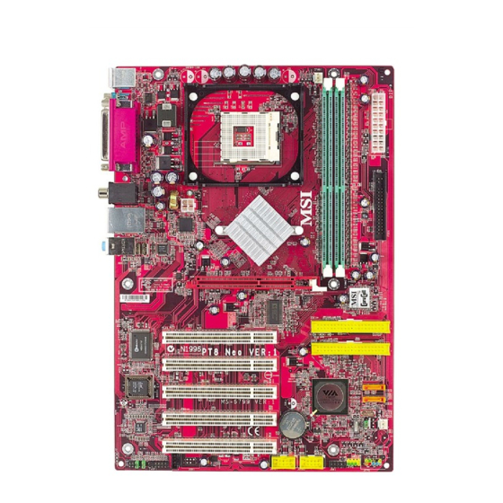
Page 10: Mainboard Layout
Line-In Line-Out Realtek 8201BL Winbond W83697HF BIOS Codec JCD1 JAUD1 JSP1 PT8 Neo Series (MS-6799 v1.X) ATX Mainboard CFAN1 PT800 AGP Slot PCI Slot 1 PCI Slot 2 PCI Slot 3 VT8237 PCI Slot 4 BATT PCI Slot 5 JUSB1... -
Page 11: Msi Special Features
MSI Special Features Color Management MSI has a unified color management rule for some connectors on the mainboards, which helps you to install the memory modules, expansion cards and other peripherals devices more easily and conveniently. Intel spec IDE ATA133 connector: yellow... -
Page 12: Corecenter
MS-6799 ATX Mainboard CoreCenter (TM) CoreCenter - contains OC Menu panel, users can determine their processor and memory type to optimize its memory capacity. This all-in-one hardware console is advanced combination of the popular PC Alert and Fuzzy Logic. Including powerful function with hardware monitor, system alert and... - Page 13 The exclusive OC Menu is fully de- veloped to support DDR400+ memory modules. By comprehensive validation of over 67 DDR400+ memory modules, MSI concluded best parameters for DRAM voltage, Vio and other BIOS settings. You can select DDR433, DDR450, DDR466 and DDR500 from DRAM frequency in BIOS setting.
-
Page 14: Live Bios™/Live Driver
Live Update 3” icon (as shown on the right) will appear on the screen. Double click the “MSI Live Update 3” icon, and the following screen will appear: Six buttons are placed on the left column of the screen. Click the desired button to start the update process. -
Page 15: Live Monitor
Live Monitor™ The Live Monitor™ is a tool used to schedule the search for the latest BIOS/drivers version on the MSI Web site. To use the function, you need to install the “MSI Live Update 3” application. After installation, the “MSI Live Monitor” icon (as shown on the right) will appear on the screen. -
Page 16: D-Bracket™ 2 (Optional)
MS-6799 ATX Mainboard D-Bracket™ 2 (Optional) D-Bracket™ 2 is an external USB bracket integrating four Diagnostic LEDs, which use graphic signal display to help users understand their system. The LEDs provide up to 16 combinations of signals to debug the system. The 4 LEDs can debug all problems that fail the system, such as VGA, RAM or other failures. - Page 17 D-Bracket™ 2 Processor Initialization - This will show information regarding the processor (like brand name, system bus, etc...) Testing RTC (Real Time Clock) Initializing Video Interface - This will start detecting CPU clock, checking type of video onboard. Then, detect and initialize the video adapter.
-
Page 18: Round Cable (Optional)
MS-6799 ATX Mainboard Round Cable (Optional) Round cable is an enhanced cable for PCI IDE and Ultra DMA controller. It has the following benefits: Data transfer rate started by 133MB/s Backward compatibility (ATA33/66/100/133) Higher performance than traditional Flat cable (data rate) -
Page 19: S-Bracket (Optional)
SPDIF jack (coaxial) SPDIF jack (optical) CPU Thermal Protection Aimed to prevent the CPU from overheating, MSI has developed a CPU Thermal Protection mechanism for Intel Protection mechanism works on a thermal signal sensor. If the mechanism senses an abnormal temperature rise, it will automatically shut down the system and the CPU temperature will then drop down and resume normal. -
Page 20: Chapter 2. Hardware Setup
Chapter 2. Hardware Setup Hardware Setup This chapter tells you how to install the CPU, memory modules, and expansion cards, as well as how to setup the jumpers on the mainboard. Also, it provides the instructions on connecting the peripheral devices, such as the mouse, keyboard, etc. -
Page 21: Quick Components Guide
MS-6799 ATX Mainboard Quick Components Guide JPW1, p.2-6 Back Panel I/O, p.2-6 AGP Slot, p.2-15 PCI Slots, p.2-15 JAUD1, p.2-11 JSP1, p.2-13 CFAN1, p.2-7 CPU, p.2-3 JUSB1, p.2-10 JUSB2, p.2-10 JCD1, p.2-9 DDR DIMMs, p.2-4 ATX1, p.2-6 FDD1, p.2-7 IDE1, IDE2, p.2-8 SATA1, SATA2, p.2-9... -
Page 22: Central Processing Unit: Cpu
Memory Speed/CPU FSB Support Matrix Memory DDR 266 400 MHz 533 MHz 800 MHz MSI Reminds You... Overheating Overheating will seriously damage the CPU and system, always make sure the cooling fan can work properly to protect the CPU from overheating. Overclocking This motherboard is designed to support overclocking. -
Page 23: Memory
MS-6799 ATX Mainboard The mainboard provides 2 slots for 184-pin, 2.5V DDR DIMM modules and supports the memory size up to 2 GB without ECC,. You can install DDR266/ DDR333/DDR400 DDR SDRAM modules on the DDR DIMM slots. To operate properly, at least one DIMM module must be installed. -
Page 24: Installing Ddr Modules
2. Insert the DIMM memory module vertically into the DIMM slot. Then push it in until the golden finger on the memory module is deeply inserted in the socket. MSI Reminds You... You can barely see the golden finger if the module is properly inserted in the socket. -
Page 25: Back Panel / Power Supply
MS-6799 ATX Mainboard Back Panel / Power Supply The back panel provides the following connectors: Parallel Mouse Keyboard COM A ATX 20-Pin Power Connector: ATX1 This connector allows you to connect to an ATX power supply. To connect to the ATX power supply, make sure the plug of the power supply is inserted in the proper orientation and the pins are aligned. -
Page 26: Connectors
+12V Sensor CFAN1 MSI Reminds You... 1. Always consult the vendors for proper CPU cooling fan. 2. CFAN1 supports the fan control. You can install the PC Alert utility that will automatically control the CPU fan speed according to the actual CPU temperature. -
Page 27: Hard Disk Connectors: Ide1/Ide2
MS-6799 ATX Mainboard ATA133 Hard Disk Connectors: IDE1 & IDE2 The mainboard has a 32-bit Enhanced PCI IDE and Ultra DMA 33/66/100/ 133 controller that provides PIO mode 0~5, Bus Master, and Ultra DMA 33/66/ 100/133 function. You can connect up to four hard disk drives, CD-ROM, 120MB Floppy and other devices. -
Page 28: Serial Ata Hdd Connectors: Sata1/Sata2 (Optional)
1 hard disk drive. SATA1 SATA2 Optional Serial ATA cable MSI Reminds You... Please do not fold the Serial ATA cable into 90-degree angle. Otherwise, the loss of data may occur during transmission. CD-In Connector: CD1 The connector is for CD-ROM audio connector. -
Page 29: Front Panel Connectors: Jfp1/Jfp2
MS-6799 ATX Mainboard Front Panel Connectors: JFP1 & JFP2 The mainboard provides two front panel connectors for electrical connection to the front panel switches and LEDs. JFP1 is compliant with Intel Front Panel I/O Connectivity Design Guide. JFP1 Power Power... -
Page 30: Front Panel Audio Connector: Jaud1
AUD_RET_R HP_ON AUD_FPOUT_L AUD_RET_L MSI Reminds You... If you don’t want to connect to the front audio header, pins 5 & 6, 9 & 10 have to be jumpered in order to have signal output directed to the rear audio ports. Otherwise, the Line-Out connector on the back panel will not function. -
Page 31: D-Bracket™ 2 Connector: Jdb1
MS-6799 ATX Mainboard D-Bracket™ 2 Connector: JDB1 The mainboard comes with a JDB1 connector for you to connect to D- Bracket™ 2. D-Bracket™ 2 is a USB Bracket that supports both USB1.1 & 2.0 spec. It integrates four LEDs and allows users to identify system problem through 16 various combinations of LED signals. -
Page 32: S-Bracket (Spdif) Connector: Jsp1 (Optional)
S-Bracket (SPDIF) Connector: JSP1 (Optional) The connector allows you to connect a S-Bracket for Sony & Philips Digital Interface (SPDIF). The S-Bracket offers 2 SPDIF jacks for digital audio transmission (one for optical fiber connection and the other for coaxial), and 2 analog Line-Out jacks for 4-channel audio output. -
Page 33: Jumpers
MS-6799 ATX Mainboard The motherboard provides the following jumpers for you to set the computer’s function. This section will explain how to change your motherboard’s function through the use of jumpers. Clear CMOS Jumper: JBAT1 There is a CMOS RAM on board that has a power supply from external battery to keep the data of system configuration. -
Page 34: Slots
The motherboard provides one AGP slot and five 32-bit PCI bus slots. AGP (Accelerated Graphics Port) Slot The AGP slot allows you to insert the AGP graphics card. AGP is an interface specification designed for the throughput demands of 3D graphics. -
Page 35: Hardware Setup
Chapter 2. Hardware Setup Hardware Setup This chapter tells you how to install the CPU, memory modules, and expansion cards, as well as how to setup the jumpers on the mainboard. Also, it provides the instructions on connecting the peripheral devices, such as the mouse, keyboard, etc. - Page 36 MS-6799 ATX Mainboard Quick Components Guide JPW1, p.2-6 Back Panel I/O, p.2-6 AGP Slot, p.2-15 PCI Slots, p.2-15 JAUD1, p.2-11 JSP1, p.2-13 CFAN1, p.2-7 CPU, p.2-3 JUSB1, p.2-10 JUSB2, p.2-10 JCD1, p.2-9 DDR DIMMs, p.2-4 ATX1, p.2-6 FDD1, p.2-7 IDE1, IDE2, p.2-8 SATA1, SATA2, p.2-9...
- Page 37 Memory Speed/CPU FSB Support Matrix Memory DDR 266 400 MHz 533 MHz 800 MHz MSI Reminds You... Overheating Overheating will seriously damage the CPU and system, always make sure the cooling fan can work properly to protect the CPU from overheating. Overclocking This motherboard is designed to support overclocking.
- Page 38 MS-6799 ATX Mainboard The mainboard provides 2 slots for 184-pin, 2.5V DDR DIMM modules and supports the memory size up to 2 GB without ECC,. You can install DDR266/ DDR333/DDR400 DDR SDRAM modules on the DDR DIMM slots. To operate properly, at least one DIMM module must be installed.
- Page 39 2. Insert the DIMM memory module vertically into the DIMM slot. Then push it in until the golden finger on the memory module is deeply inserted in the socket. MSI Reminds You... You can barely see the golden finger if the module is properly inserted in the socket.
- Page 40 MS-6799 ATX Mainboard Back Panel / Power Supply The back panel provides the following connectors: Parallel Mouse Keyboard COM A ATX 20-Pin Power Connector: ATX1 This connector allows you to connect to an ATX power supply. To connect to the ATX power supply, make sure the plug of the power supply is inserted in the proper orientation and the pins are aligned.
- Page 41 +12V Sensor CFAN1 MSI Reminds You... 1. Always consult the vendors for proper CPU cooling fan. 2. CFAN1 supports the fan control. You can install the PC Alert utility that will automatically control the CPU fan speed according to the actual CPU temperature.
- Page 42 MS-6799 ATX Mainboard ATA133 Hard Disk Connectors: IDE1 & IDE2 The mainboard has a 32-bit Enhanced PCI IDE and Ultra DMA 33/66/100/ 133 controller that provides PIO mode 0~5, Bus Master, and Ultra DMA 33/66/ 100/133 function. You can connect up to four hard disk drives, CD-ROM, 120MB Floppy and other devices.
- Page 43 1 hard disk drive. SATA1 SATA2 Optional Serial ATA cable MSI Reminds You... Please do not fold the Serial ATA cable into 90-degree angle. Otherwise, the loss of data may occur during transmission. CD-In Connector: CD1 The connector is for CD-ROM audio connector.
- Page 44 MS-6799 ATX Mainboard Front Panel Connectors: JFP1 & JFP2 The mainboard provides two front panel connectors for electrical connection to the front panel switches and LEDs. JFP1 is compliant with Intel Front Panel I/O Connectivity Design Guide. JFP1 Power Power...
- Page 45 AUD_RET_R HP_ON AUD_FPOUT_L AUD_RET_L MSI Reminds You... If you don’t want to connect to the front audio header, pins 5 & 6, 9 & 10 have to be jumpered in order to have signal output directed to the rear audio ports. Otherwise, the Line-Out connector on the back panel will not function.
- Page 46 MS-6799 ATX Mainboard D-Bracket™ 2 Connector: JDB1 The mainboard comes with a JDB1 connector for you to connect to D- Bracket™ 2. D-Bracket™ 2 is a USB Bracket that supports both USB1.1 & 2.0 spec. It integrates four LEDs and allows users to identify system problem through 16 various combinations of LED signals.
-
Page 47: Audio Function
S-Bracket (SPDIF) Connector: JSP1 (Optional) The connector allows you to connect a S-Bracket for Sony & Philips Digital Interface (SPDIF). The S-Bracket offers 2 SPDIF jacks for digital audio transmission (one for optical fiber connection and the other for coaxial), and 2 analog Line-Out jacks for 4-channel audio output. - Page 48 MS-6799 ATX Mainboard The motherboard provides the following jumpers for you to set the computer’s function. This section will explain how to change your motherboard’s function through the use of jumpers. Clear CMOS Jumper: JBAT1 There is a CMOS RAM on board that has a power supply from external battery to keep the data of system configuration.
- Page 49 The motherboard provides one AGP slot and five 32-bit PCI bus slots. AGP (Accelerated Graphics Port) Slot The AGP slot allows you to insert the AGP graphics card. AGP is an interface specification designed for the throughput demands of 3D graphics.
-
Page 50: Chapter 3. Bios Setup
Chapter 3. BIOS Setup BIOS Setup This chapter provides information on the BIOS Setup program and allows you to configure the system for optimum use. You may need to run the Setup program when: An error message appears on the screen during the system booting up, and requests you to run SETUP. -
Page 51: The Main Menu
MS-6799 ATX Mainboard The Main Menu ® Once you enter Phoenix-Award BIOS CMOS Setup Utility, the Main Menu (Figure 1) will appear on the screen. The Main Menu allows you to select from twelve setup functions and two exit choices. Use arrow keys to select among the items and press <Enter>... - Page 52 BIOS Setup PC Health Status This entry shows your PC health status. Frequency/Voltage Control Use this menu to specify your settings for frequency/voltage control. Load High Performance Defaults Use this menu to load the BIOS values for the best system performance, but the system stability may be affected.
-
Page 53: Standard Cmos Features
MS-6799 ATX Mainboard Standard CMOS Features The items in Standard CMOS Features Menu are divided into 11 categories. Each category includes no, one or more than one setup items. Use the arrow keys to highlight the item and then use the <PgUp> or <PgDn> keys to select the value you want in each item. - Page 54 your hard disk drive type is not matched or listed, you can use Manual to define your own drive type manually. If you select Manual, related information is asked to be entered to the follow- ing items. Enter the information directly from the keyboard. This information should be provided in the documentation from your hard disk vendor or the system manufacturer.
-
Page 55: Frequency/Voltage Control
’s newly developed CoreCell to detect the load balance of CPU while running programs, and to adjust the best CPU frequency automatically. When the motherboard detects CPU is running programs, it will speed up CPU automatically to make the program run smoothly and faster. - Page 56 MSI Reminds You... 1. Even though the Dynamic Overclocking Technology is more stable than manual overclocking, basically, it is still risky. We suggest user to make sure that your CPU can afford to overclocking regularly first. If you find the PC appears to be...
- Page 57 PCI bus. The settings are: Enabled, Disabled. Spread Spectrum When the motherboard’s clock generator pulses, the extreme values (spikes) of the pulses creates EMI (Electromagnetic Interference). The Spread Spectrum function reduces the EMI generated by modulating the pulses so that the spikes of the pulses are reduced to flatter curves.
-
Page 58: Load High Performance/Optimized Defaults
Pressing ‘Enter’ loads the default BIOS values that enable the best system performance but may lead to a stability issue. MSI Reminds You... The option is for power or overclocking users only. Use of high performance defaults will tighten most timings to increase the system performance. -
Page 59: Set Supervisor/User Password
MS-6799 ATX Mainboard Set Supervisor/User Password When you select this function, a message as below will appear on the screen: Type the password, up to eight characters in length, and press <Enter>. The password typed now will replace any previously set password from CMOS memory. -
Page 60: Appendixa. Using 4- Or 6-Channel Audio Function
Using 4- or 6-Channel Audio Function Appendix A: Using 2-, 4- & 6-Channel Audio Function The mainboard is equipped with Realtek ALC655 chip, which provides support for 6-channel audio output, including 2 Front, 2 Rear, 1 Center and 1 Subwoofer channel. ALC655 allows the board to attach 4 or 6 speakers for better surround sound effect. -
Page 61: Installing The Audio Driver
MS-6799 ATX Mainboard Installing the Audio Driver You need to install the driver for Realtek ALC655 chip to function properly before you can get access to 4-/6-channel audio operations. Follow the procedures described below to install the drivers for different operating systems. - Page 62 3 . 3 . 3 . 3 . Click Click N e x t N e x t to install the AC’97 Audio software. to install the AC’97 Audio software. Click N e x t to install the AC’97 Audio software. Click Click N e x t...
-
Page 63: Software Configuration
MS-6799 ATX Mainboard Software Configuration After installing the audio driver, you are able to use the 4-/6-channel audio feature now. Click the audio icon right corner of the screen to activate the AC97 Audio Configuration. Sound Effect Here you can select a sound effect you like from the Environment list. - Page 64 Here it provides the Karaoke function which will automatically remove human voice (lyrics) and leave melody for you to sing the song. Note that this function applies only for 2-channel audio operation. Just check the Voice Cancellation box and then click OK to activate the Karaoke function.
- Page 65 MS-6799 ATX Mainboard Equalizer Here you regulate each equalizer for current playing digital sound sources. You may choose the provided sound effects, and the equalizer will adjust automatically. If you like, you may also load an equalizer setting or make an new equalizer setting to save as an new one by using the buttons Load and Save.
-
Page 66: Speaker Configuration
Speaker Configuration In this tab, you can easily configure your multi-channel audio function and speakers. 1. Select the audio configuration below which is identical to the audio jack in your mainboard. 2. Select a desired multi-channel operation from Number of Speaker. a. -
Page 67: Speaker Test
MS-6799 ATX Mainboard Speaker Test You can use this tab to test each connected speaker to ensure if 4- or 6- channel audio operation works properly. If any speaker fails to make sound, then check whether the cable is inserted firmly to the connector or replace the bad speakers with good ones. -
Page 68: Hrtf Demo
MSI Reminds You... 1. 6 speakers appear on the “Speaker Test” tab only when you select “6-Channel Mode” in the “Number of Speakers” col- umn in “Speaker Configuration” tab. If you select “4-Chan- nel Mode”, only 4 speakers appear on the window. - Page 69 MS-6799 ATX Mainboard General In this tab it provides some information about this AC97 Audio Configu- ration utility, including Audio Driver Version, DirectX Version, Audio Control- ler & AC97 Codec. You may also select the language of this utility by choosing from the Language list.
-
Page 70: Using The Back Panel Only
Using the optional S-Bracket If your motherboard supports S-Bracket and you have installed S- Bracket in the computer, you can connect two speakers to back panel’s Line-Out connector, and the rest of speakers to S-Bracket. - Page 71 MS-6799 ATX Mainboard 4-Channel Mode for 4-Speaker Output The audio jacks on the back panel always provide 2-channel analog audio output function, however these audio jacks can be transformed to 4- or 6- channel analog audio jacks by selecting the corresponding multi-channel operation from No.
- Page 72 MSI Reminds You... If the audio signals coming from the Center and Subwoofer speaker are swapped when you play video or music on the computer, a converter may be required to exchange center and subwoofer audio signals. The converter can be purchased from a speaker store.
- Page 73 MS-6799 ATX Mainboard 4-Channel Analog Audio Output Line Out (Front channels) Line In Optical SPDIF jack Coaxial SPDIF jack Line Out (Center and Subwoofer channel, but no functioning in this mode) Line Out (Rear channels) Coaxial SPDIF jack Back Panel...
- Page 74 6-Channel Analog Audio Output Line Out (Front channels) Line In Optical SPDIF jack Coaxial SPDIF jack Line Out (Center and Subwoofer channel) Line Out (Rear channels) Coaxial SPDIF jack Back Panel Using 4- or 6-Channel Audio Function Description: Connect two speakers to back panel’s Line Out connector and four speakers to both Line Out connectors of S-Bracket.
- Page 75 MS-6799 ATX Mainboard Digital Audio Output (2-Channel only) For digital audio output, use the SPDIF (Sony & Philips Digital Interface) connectors supplied by S-Bracket. First, connect the SPDIF speakers to the appropriate SPDIF jack, and then select the audio channel you desire through the control panel of speakers.
-
Page 76: Appendixb. Via Vt8237 Serial Ata Raid Introduction
Appendix. Using 4- or 6-Channel Appendix B: VIA VT8237 Serial ATA Audio Function The Southbridge VT8237 provides a hybrid solution that combines two independent SATA ports for support of up to two Serial ATA (Serial ATA RAID) drives. Serial ATA (SATA) is the latest generation of the ATA interface. SATA hard drives deliver blistering transfer speeds of up to 150MB/sec. - Page 77 MS-6799 ATX Mainboard This section gives a brief introduction on the RAID-related background knowledge and a brief introduction on VIA SATA RAID Host Controller. For users wishing to install their VIA SATA RAID driver and RAID software, proceed to Driver and RAID Software Installation section.
- Page 78 RAID 0 (Striping) RAID 0 reads and writes sectors of data interleaved between multiple drives. If any disk member fails, it affects the entire array. The disk array data capacity is equal to the number of drive members times the capacity of the smallest member.
-
Page 79: Bios Configuration
MS-6799 ATX Mainboard BIOS Configuration When the system powers on during the POST (Power-On Self Test) process, press <Tab> key to enter the BIOS configuration. The Serial ATA RAID volume may be configured using the VIA Tech. RAID BIOS. Always use the arrow keys to navigate the main menu, use up and down arrow key to select the each item and press <Enter>... - Page 80 Create Disk Array Use the up and down arrow keys to select the Create Array command and press <Enter>. MSI Reminds You... The “Channel”, “Drive Name”, “Mode” and “Size (GB)” in the following example might be different from your system.
- Page 81 MS-6799 ATX Mainboard After array mode is selected, there are two methods to create a disk array. One method is “Auto Setup” and the other one is “Select Disk Drives”. Auto Setup allows BIOS to select the disk drives and create arrays automatically, but it does not duplicate the mirroring drives even if the user selected Create and duplicate for RAID 1.
- Page 82 MSI Reminds You... Even though 64KB is the recommended setting for most users, you should choose the block size value which is best suited to your specific RAID usage model. 4KB: For specialized usage models requiring 4KB blocks 8KB: For specialized usage models requiring 8KB blocks...
- Page 83 MS-6799 ATX Mainboard Delete Disk Array A RAID can be deleted after it has been created. To delete a RAID, use the following steps: 1. Select Delete Array in the main menu and press <Enter>. The channel column will be activated.
- Page 84 VIA VT8237 Serial ATA RAID Introduction Create and Delete Spare Hard Drive If a RAID 1 array is created and there are drives that do not belong to other arrays, the one that has a capacity which is equal to or greater than the array capacity can be selected as a spare drive for the RAID 1 array.
- Page 85 MS-6799 ATX Mainboard View Serial Number of Hard Drive Highlight Serial Number View and press <Enter>. Use arrow key to select a drive, the selected drive’s serial number can be viewed in the last column. The serial number is assigned by the disk drive manufacturer.
- Page 86 Duplicate Critical RAID 1 Array When booting up the system, BIOS will detect if the RAID 1 array has any inconsistencies between user data and backup data. If BIOS detects any inconsistencies, the status of the disk array will be marked as critical, and BIOS will prompt the user to duplicate the RAID 1 in order to ensure the backup data consistency with the user data.
- Page 87 MS-6799 ATX Mainboard Rebuild Broken RAID 1 Array When booting up the system, BIOS will detect if any member disk drives of RAID has failed or is absent. If BIOS detects any disk drive failures or missing disk drives, the status of the array will be marked as broken.
- Page 88 3. Choose Replacement Drive and Rebuild: This item enables users to select an already-connected hard drive to rebuild the broken array. After choosing a hard drive, the channel column will be activated. Highlight the target hard drive and press <Enter>, a warning message will appear.
- Page 89 Windows XP installation Existing Windows XP Driver Installation 1. Insert the MSI CD into the CD-ROM drive. 2. The CD will auto-run and the setup screen will appear. 3. Under the Driver tab, click on VIA SATA RAID Utility.
- Page 90 VIA SATA RAID Utility contains the following key features: Serial ATA RAID driver for Windows XP VIA SATA RAID utility RAID0 and RAID1 functions Insert the MSI CD and click on the VIA SATA RAID Utility to install the software. VIA VT8237 Serial ATA RAID Introduction B-15...
- Page 91 MS-6799 ATX Mainboard The InstallShield Wizard will begin automatically for installation. Click on the Next button to proceed the installation in the welcoming window. Put a check mark in the check box to install the feature you want. Then click Next button to proceed the installation.
-
Page 92: Using Via Raid Tool
Using VIA RAID Tool Once the installation is complete, go to Start ---> Programs --->VIA -- ->raid_tool.exe to enable VIA RAID Tool. After the software is finished installation, it will automatically started every time Windows is initiated. You may double-click on the in the system tray of the tool bar to launch the VIA RAID Tool utility. - Page 93 MS-6799 ATX Mainboard The main interface is divided into two windows and the toolbar above contain the main functions. Click on these toolbar buttons to execute their specific functions. The left windowpane displays the controller and disk drives and the right windowpane displays the details of the controller or disk drives.
- Page 94 Click on the plus (+) symbol next to Array 0---RAID 0 to see the details of each disk. You may also use the same Array 0---RAID 1. VIA VT8237 Serial ATA RAID Introduction button to view the statuses of B-19...
- Page 95 MS-6799 ATX Mainboard Click on the plus (+) symbol next to Array 0---RAID 1 to see the details of each disk. B-20...