Table of Contents
Advertisement
WJ-PC200
WJ-PR204
Before attempting to connect or operate this product, please read these instructions carefully and
save this manual for future use.
Operating Instructions
WJ-PR204 / WJ-PR204E
Model No.
RECEIVER (4-channel)
WJ-PR201 / WJ-PR201E
RECEIVER (1-channel)
WJ-PC200 / WJ-PC200E
Coaxial - LAN Converter
CAMERA
Advertisement
Table of Contents

Related Manuals for Panasonic WJ-PR204


Summary of Contents for Panasonic WJ-PR204
-
Page 1: Operating Instructions
Operating Instructions Coaxial - LAN Converter WJ-PR204 / WJ-PR204E Model No. RECEIVER (4-channel) WJ-PR201 / WJ-PR201E RECEIVER (1-channel) WJ-PC200 / WJ-PC200E CAMERA WJ-PC200 WJ-PR204 Before attempting to connect or operate this product, please read these instructions carefully and save this manual for future use. - Page 2 2006/95/EC og 2004/108/EC. ference at his own expense. FCC Caution: To assure continued compliance, (example - use only shielded interface cables For use only with power supply Panasonic, when connecting to computer or peripheral UP0651S-57PB devices). Any changes or modifications not expressly approved by the party responsible for compliance could void the user’s authority to...
- Page 3 If you lose the fuse cover the plug must not be used until a replacement cover is obtained. A replacement fuse cover can be purchased from your local Panasonic Dealer. IF THE FITTED MOULDED PLUG IS UNSUITABLE FOR THE SOCKET OUTLET IN YOUR HOME THEN THE FUSE SHOULD BE REMOVED AND THE PLUG CUT OFF AND DISPOSED OF SAFELY.
-
Page 4: Important Safety Instructions
Important safety instructions Important safety instructions 1. Read these instructions. 2. Keep these instructions. 3. Heed all warnings. 4. Follow all instructions. 5. Do not use this apparatus near water. 6. Clean only with dry cloth. 7. Do not block any ventilation openings. Install in accordance with the manufacturer's instructions. -
Page 5: Table Of Contents
1.5.2 CAUTION .......................15 General Precautions ..................15 Precautions for Installation ................17 Parts and functions .................21 WJ-PR204/WJ-PR204E/WJ-PR201/WJ-PR201E (connects to the network device) ......................21 WJ-PC200/WJ-PC200E (connects to the camera) ........23 Understanding the Indicators ...............24 Mounting the Unit ..................25 Mounting the camera side unit ..............25 Mounting the receiver side unit to a Rack ...........26... -
Page 6: Preface
It is capable of implementing long distance, high speed digital data transmission on existing coaxial cables with low setup costs. With the built-in PoE function, the unit is able to supply power to Panasonic network cameras, which eliminates the need for installing power outlets for the cameras. -
Page 7: Main Features
There are limitations on the combinations of the cameras to be connected, the type of power supply and transmission range to the receiver side units. Please see page 30 for details. For information on network cameras recommended by Panasonic, see the Panasonic support site (http://security.panasonic.com/pss/security/support/info.html). -
Page 8: Introduction
1 Preface 1.2 Introduction About the user manuals • Instruction Manual (this document): Explains the safety precautions, instructions for use and installation, installation and setup procedures, and other information. The external appearance and other parts shown in this manual may differ from the actual product within the scope that will not interfere with normal use due to improvement of the product. -
Page 9: Other Information
OR THE CORRESPONDING PRODUCT (S). Disclaimer of warranty IN NO EVENT SHALL Panasonic System Networks Co., Ltd. BE LIABLE TO ANY PARTY OR ANY PERSON, EXCEPT FOR REPLACEMENT OR REASONABLE MAINTENANCE OF THE PRODUCT, FOR THE CASES, INCLUDING BUT NOT LIMITED TO BELOW: 1. - Page 10 1 Preface Network security As you will use this unit connected to a network, your attention is called to the following security risks. Leakage or theft of information through this unit Use of this unit for illegal operations by persons with malicious intent Interference with or stoppage of this unit by persons with malicious intent It is your responsibility to take precautions such as those described below to protect yourself against the above network security risks.
-
Page 11: Included Items
1.4 Included Items Confirm that the following items are included in the unit’s packaging. WJ-PR204/WJ-PR204E/WJ-PR201/WJ-PR201E • Operating Instructions (this document) (1 pc.) • Warranty Card (1 pc.) WJ-PR204, WJ-PR201 • AC adapter (1 pc.) • AC Cord (1 pc.) WJ-PR204, WJ-PR201 •... -
Page 12: For Your Safety
1 Preface 1.5 For Your Safety To prevent severe injury and loss of life/property, read this section carefully before using the unit to ensure proper and safe operation of your unit. 1.5.1 WARNING Consult an authorized dealer for mounting. • Experience and knowledge are required to perform mounting of the unit. - Page 13 1 Preface Always hold the plug when unplugging the power cord. PR204 PR201 • Otherwise, the cord may be damaged and result in a fire or electric shock. The exclusively designed mount bracket shall be used. PR204 PR201 • Failure to observe this may cause a drop resulting in injury or accidents. Use the exclusively designed mount bracket for installation.
- Page 14 1 Preface Avoid installing this product in the locations where salt damage occurs or corrosive gas is produced. • Otherwise, the mounting portions will deteriorate and accidents such as a fall of the product may occur. Do not damage the power cable. PR204 PR201 •...
-
Page 15: Caution
1 Preface Never touch the power plug with wet hands. PR204 PR201 • This may result in electric shock. Do not pour or wet the unit. • This may result electric shock or fire. Turn the power off immediately and contact qualified service personnel for service. - Page 16 1 Preface allow the power to be quickly turned off, use a distribution panel with a circuit breaker capable of disconnecting the power, or connect this unit to a power source controller. 5. Handle this product with care. • Do not drop this product, nor apply shock or vibration to the product. Failure to observe this may cause trouble.
-
Page 17: Precautions For Installation
1 Preface 1.7 Precautions for Installation Install the unit in accordance with electrical equipment technical standards. Before beginning to install and connect the unit, check and prepare all necessary peripheral equipment and cables. Turn off the power supply of the unit, camera, and other components before connecting them. - Page 18 • When mounting 3 to 4 connected receiver side units to the rack, use the following bracket (locally procured). – Rack mount bracket: For WJ-PR204/WJ-PR201: BY-HCA10A For WJ-PR204E/WJ-PR201E: BY-HCA10CE • Available racks – EIA standard rack or equivalent (third party) EIA19 type •...
- Page 19 1 Preface Screw tightening • The screws and bolts must be tightened with an appropriate tightening torque according to the material and strength of the installation area. • Do not use an impact driver. Use of an impact driver may damage the screws or cause tightening excessively.
- Page 20 1 Preface Mounting and connections • Do not mount camera side units above or below other camera side units. This can cause transmission interference. When mounting several camera side units in the same area, mount them side by side each other. •...
-
Page 21: Parts And Functions
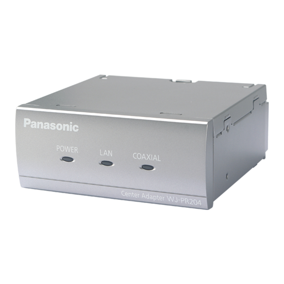
Indicates that the receiver side unit is connected to the camera side unit (see page 24). Note The WJ-PR204 is used as an example in some of the illustrations in this document. Rear view WJ-PR201, WJ-PR201E BNC connector Connects the receiver side unit to the camera side unit with a coaxial cable (see page 37). - Page 22 2 Parts and functions WJ-PR204, WJ-PR204E BNC connector Connects the receiver side unit to the camera side unit with a coaxial cable (see page 37). Network connector Connects the receiver side unit to a network device with an Ethernet cable (see page 38).
-
Page 23: Wj-Pc200/Wj-Pc200E (Connects To The Camera)
2 Parts and functions 2.2 WJ-PC200/WJ-PC200E (connects to the camera) Front view LINK Indicator Displays the status of the camera side unit (see page 24). Network connector Connects the camera side unit to a network camera with an Ethernet cable (see page 34). BNC connector Connects the camera side unit to the receiver side unit with a coaxial cable (see page 35). -
Page 24: Understanding The Indicators
2 Parts and functions 2.3 Understanding the Indicators The light indicators change depending on the operating status of the camera and receiver side units. Receiver side unit Indicator Light Status Meaning Green (lit) The receiver side unit is active. POWER The power source is not supplied to the receiver side unit. -
Page 25: Mounting The Unit
3 Mounting the Unit 3 Mounting the Unit 3.1 Mounting the camera side unit Please read the following information before mounting the camera side unit. IMPORTANT • Mount the camera side unit to a secure location that is firm enough to support its weight (approximately 110 g (0.24 lb)) and the weight of the cabling. -
Page 26: Mounting The Receiver Side Unit To A Rack
3 Mounting the Unit 3.2 Mounting the receiver side unit to a Rack By using the Rack Mount Connecting Fitting (locally procured), 3 or 4 connected receiver side units can be mounted to a rack. Prepare the Rack Mount Connecting Fitting (BY-HCA10A), which includes the following items. - Page 27 3 Mounting the Unit Note • When mounting the receiver side units, place one of the units to either the left or right edge and connect then connect the units. • The BY-HCA10A rack mount bracket comes with 2 underside continuous connecting bracket and 32 screws (flat-head: M36 mm {1/4 inches}).
- Page 28 3 Mounting the Unit 2. Secure the mounting brackets of the BY-HCA10A to both sides of the connected receiver side units with the screws included with the BY-HCA10A. (Recommended torque 0.7±0.3 N·m {0.52±0.22 lbf·ft}) Screw (M3×6 mm {1/4 inches}: Screw Rack mount connecting (M3×6 mm {1/4 inches}: fitting (accessory)) ×...
- Page 29 3 Mounting the Unit 3. Secure the connected receiver side units to the separately-sold racks. • Securely mount the receiver side units to the rack with the rack mounting screws (locally procured, nominal diameter 5 mm {3/16 inches} tapping). Rack mounting screw (locally procured) ×...
-
Page 30: Connecting The Unit
Max. 100 m Max. 200 m {656 feet}: {164 feet} {328 feet} PoE+ camera Max. 300 m {984 feet}: Cameras recommended by Panasonic Max. 100 m Max. 100 m Max. 300 m {984 feet}: PoE AC adaptor {328 feet} {328 feet} camera Max. - Page 31 Camera side unit Receiver side unit Switching hub For information about network cameras recommended by Panasonic, visit our web site. http://security.panasonic.com/pss/security/support/info.html Use a PoE camera that consumes no more than 6.5 W. When connecting a PoE camera or PoE+ camera to an external power supply, make sure to use the included PoE incompatible cable.
-
Page 32: When Using A 4-Channel Receiver Side Unit
{328 feet} {16 feet 4-27/32 inch For information about network cameras recommended by Panasonic, visit our web site. http://security.panasonic.com/pss/security/support/info.html When connecting a PoE camera or PoE+ camera to an external power supply, make sure to use the included PoE incompatible cable. When the camera side unit can be installed near the camera, connect the PoE incompatible cable directly to the camera. - Page 33 4 Connecting the Unit 4-channel Receiver Side Unit connection example In this example, the camera is powered by PoE and the receiver side unit is powered by an AC adaptor. Ethernet cable (Cat-5e or higher, straight) Ethernet cable (Cat-5e or higher, straight) Coaxial cable Camera Camera side unit...
-
Page 34: Connections
4 Connecting the Unit 4.2 Connections Before proceeding with the connections, turn off the power of the unit and other network devices that will be connected. Prepare the necessary peripheral equipment and cables. The ethernet cable and coaxial cable are locally procured. IMPORTANT •... - Page 35 4 Connecting the Unit 2. First pass the coaxial cable through the BNC connector cover (accessory), then connect the coaxial cable to the BNC connector of the camera side unit. BNC connector Coaxial cable BNC connector cover (Included parts of camera side unit) To receiver side unit IMPORTANT •...
- Page 36 4 Connecting the Unit 3. Secure the BNC connector cover using the screw (included parts of camera side unit) to the camera side unit. (Recommended torque 0.6±0.2 N·m {6±2 k f·cm}) Screw (body diameter 2.6×10 mm {3/8 inches}: included parts of camera side unit) BNC connector cover (Included parts of camera side unit) 4.
- Page 37 4 Connecting the Unit • Keep the removed BNC connector cover cap (accessory) for future use. BNC connector terminal × 4 BNC connector cover cap (accessory) Coaxial cable BNC connector cover (Accessory of receiver side unit) • The illustrations below show an example to establish the 2-channel connection to a 4-channel unit model.
- Page 38 4 Connecting the Unit 5. Secure the BNC connector cover with included the screw (M2.6 10 mm {3/8 inches}: included parts) to the receiver side unit. (Recommended torque 0.6±0.2 N·m {6±0.2 k f·cm}) Screw (body diameter 2.6×10 mm {3/8 inches}: accessory of receiver side unit) BNC connector cover...
- Page 39 4 Connecting the Unit 7. Connect the output connector of the AC adapter (accessory) to the DC jack at the rear of the receiver side unit, and plug the AC power cord into the power outlet. AC adapter output connector Cable fixing hooks AC cord (accessory)
- Page 40 4 Connecting the Unit 9. Check the camera shooting screen on the PC, via the coaxial - LAN converter. • Connect the PC to the system, open Internet Explorer, enter the IP address of the camera, and press the Enter key. The live image of the connected camera is displayed on the PC screen.
-
Page 41: Maintenance Screen Of Coaxial - Lan Converter
• If you plan to update the adapter’s firmware, download the latest version of the coaxial - LAN converter’s firmware from the Panasonic support site (http://security.panasonic.com/pss/security/support/) and save it on the computer before you change the IP address of the computer. -
Page 42: Accessing The Maintenance Screen
5 Maintenance Screen of coaxial - LAN converter 5.1 Accessing the Maintenance Screen 5.1.1 Temporarily Changing the Computer’s IP Address Temporarily change the IP address assigned to your computer to access the coaxial - LAN converter’s maintenance screen. The procedure for changing the IP address differs depending on the operating system used. - Page 43 5 Maintenance Screen of coaxial - LAN converter 5. Select [Use the following IP address], then click [OK] after entering the IP address ) and Subnet mask ( ). Substitute “***” in “192.168.249.***” with any number between 1 and 254 other than 249 (this is the address assigned to the receiver side unit).
-
Page 44: Accessing The Maintenance Screen
4. Enter the user name and password. – Default user name: Model no. – Default password: 999999 • The screen shown here depicts the screen shown when using Windows 7. Model no. User name Password WJ-PR204/WJ-PR204E WJ-PR204 999999 WJ-PR201/WJ-PR201E WJ-PR201 999999 WJ-PC200/WJ-PC200E WJ-PC200... - Page 45 5 Maintenance Screen of coaxial - LAN converter 5. Click [OK]. • The maintenance screen is displayed. Receiver side unit WJ-PR204 Camera side unit WJ-PC200 IMPORTANT • Only a PC connected to the coaxial - LAN converter’s network connector can display the maintenance screen and perform firmware updates, etc.
-
Page 46: Maintenance Screen Overview
5 Maintenance Screen of coaxial - LAN converter 5.1.3 Maintenance Screen Overview Model number Name of current screen Click to jump to the corresponding page Click to restart the coaxial - LAN converter Click to view the copyright information Contents of the current screen Click to update the displayed information IMPORTANT •... -
Page 47: Using The Maintenance Screen
- LAN converter, and the connection status of other coaxial - LAN converters on the [Status] screen. 1. Access the maintenance screen of the coaxial - LAN converter. 2. Click [Status]. WJ-PR204 The screen shown above is the maintenance screen of the receiver side unit. IMPORTANT •... - Page 48 5 Maintenance Screen of coaxial - LAN converter Items Description PLC link status (only Displays the status of the connection between the camera side unit displayed for the and receiver side unit. [Connected] is displayed when there is a camera side unit) connection, and [Disconnected] is displayed when there is no connection.
-
Page 49: Updating The Coaxial - Lan Converter's Firmware
When you update the coaxial - LAN converter firmware, be sure to download the latest version of the coaxial - LAN converter’s firmware to the PC before changing the IP address of the PC. You can download the firmware from the Panasonic support site (http://panasonic.net/pss/security/products/coax/index.html). -
Page 50: Changing Coaxial - Lan Converter's Settings
7. Click [Restart], then click [Reset] button in the restart tab. WJ-PR204 After restarting, make connections using the changed IP address displayed in the maintenance screen. -
Page 51: Troubleshooting
6 Troubleshooting 6 Troubleshooting Before sending the unit in for repairs, check if the problem can be resolved by following the troubleshooting steps. If the problem cannot be solved by the steps in the troubleshooting, contact an authorized service center. 6.1 Indicator Display Issues Problem Cause and Remedy... -
Page 52: Transmission Speed
6 Troubleshooting Problem Cause and Remedy The receiver side unit’s • The unit is not receiving power. COAXIAL indicator is → Confirm that the AC cord is connected to the power outlet not lit. and the AC adapter output connector is connected to the DC jack of the receiver side unit (see page 39). -
Page 53: Poe+/Poe Issues
6 Troubleshooting 6.3 PoE+/PoE Issues Problem Cause and Remedy PoE+/PoE cameras • The connection distance may be too long. connected to the → The PoE function cannot supply power to devices camera side unit do not connected at distances. function. →... -
Page 54: Specifications
7 Specifications 7 Specifications Receiver side unit Items Specifications Power Supply Use the included AC adapter. • INPUT: 100-240 V/ 50/60 Hz • OUTPUT: DC 57 V/ 1.14 A Use the PoE power supply. • PoE DC 48 V/ Approx.265 mA Power Consumption Use the included AC adapter. - Page 55 (0.24 lb) Finish Main unit: PC/ABS, sail white BNC connector cover (1 ch.): ABS, white Coaxial Interface Items Specifications Standard Panasonic original system Frequency Range 2 MHz–28 MHz Data Transfer Mode Wavelet OFDM Access Method CSMA/CA Error Correction Reed-Solomon Code + Convolutional Code (Viterbi decoding)
- Page 56 The maximum distance that can be connected with a coaxial cable varies depending on the camera used. For more information, see page 30, 32. For information about the cameras specified by Panasonic, visit our website: http://security.panasonic.com/pss/security/support/info.html Maintenance Screen Specifications...
- Page 57 FTP. ® For information about the cameras recommended by Panasonic to be used for the camera side unit, see our website: http://security.panasonic.com/pss/security/support/info.html The maximum length of an Ethernet cable used to connect a PoE+ camera is 50 m (164 feet).
- Page 58 Notes Operating Instructions...
- Page 59 Notes Operating Instructions...
- Page 60 For more information about collection and recycling, please contact your local municipality. Penalties may be applicable for incorrect disposal of this waste, in accordance with national legislation. For U.S. and Canada: Panasonic System Communications Company of North America, Unit of Panasonic Corporation of North America www.panasonic.com/business/ For customer support, call 1.800.528.6747...