Panasonic WJ-GXE500E Installation Manual
Network video encoder
Hide thumbs
Also See for WJ-GXE500E:
- Operating instructions manual (73 pages) ,
- Installation manual (32 pages)
Table of Contents
Advertisement
Quick Links
Installation Guide
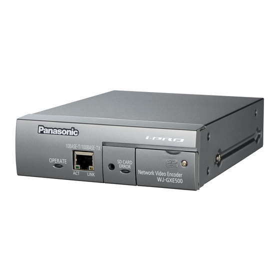
Network Video Encoder
WJ-GXE500
Model No.
WJ-GXE500E
1 0 B A S E -T
/1 0 0 B A S E
-T X
O P E R A T
E
S D C A R D
E R R O R
A C T
L IN K
Before attempting to connect or operate this product, please read these
instructions carefully and save this manual for future use.
The model number is abbreviated in some descriptions in this manual.
Advertisement
Table of Contents

Related Manuals for Panasonic WJ-GXE500E


Summary of Contents for Panasonic WJ-GXE500E
-
Page 1: Installation Guide
Installation Guide Network Video Encoder WJ-GXE500 Model No. WJ-GXE500E 1 0 B A S E -T /1 0 0 B A S E -T X O P E R A T S D C A R D E R R O R... - Page 2 WARNING: • Apparatus shall be connected to a mains sock- et outlet with a protective earthing connection. • The mains plug or an appliance coupler shall remain readily operable. • To prevent fire or electric shock hazard, do not expose this apparatus to rain or moisture. •...
-
Page 3: Table Of Contents
Contents Important safety instructions ......................4 Limitation of liability ........................5 Disclaimer of warranty ........................5 Preface ............................5 Main functions ..........................6 About the user manuals ........................ 7 System requirements for a PC ...................... 7 Trademarks and registered trademarks..................8 About copyright and license...................... -
Page 4: Important Safety Instructions
Important safety instructions 1) Read these instructions. 2) Keep these instructions. 3) Heed all warnings. 4) Follow all instructions. 5) Do not use this apparatus near water. 6) Clean only with dry cloth. 7) Do not block any ventilation openings. Install in accordance with the manufacturer's instruc- tions. -
Page 5: Limitation Of Liability
IMPROVEMENTS OF THIS PUBLICATION AND/OR THE CORRESPONDING PRODUCT (S). Disclaimer of warranty IN NO EVENT SHALL Panasonic System Networks Co., Ltd. BE LIABLE TO ANY PARTY OR ANY PERSON, EXCEPT FOR REPLACEMENT OR REASONABLE MAINTENANCE OF THE PRODUCT, FOR THE CASES, INCLUDING BUT NOT LIMITED TO BELOW:... -
Page 6: Main Functions
Note: • It is necessary to configure the network settings of the PC and its network environment to monitor images and audio from the unit on the PC. It is also necessary to install a web browser on the PC. Main functions Motion adaptive interlace/progressive conversion function It is possible to generate digital images with smooth movements by detecting moving areas to pro-... -
Page 7: About The User Manuals
About the user manuals There are 2 sets of operating instructions for the WJ-GXE500 (NTSC model), WJ-GXE500E (PAL model) as follows. • Installation Guide: Explains how to install and connect devices. • Operating Instructions (PDF): Explains how to perform the settings and how to operate this unit. ®... -
Page 8: Trademarks And Registered Trademarks
Important: • When using a PC that does not meet the previously mentioned requirements, displaying of images may become slower or the web browser may become inoperable. • Audio may not be heard if a sound card is not installed on a PC. Audio may be interrupted depending on the network environment. -
Page 9: Network Security
Network security As you will use this unit connected to a network, your attention is called to the following security risks. q Leakage or theft of information through this unit w Use of this unit for illegal operations by persons with malicious intent e Interference with or stoppage of this unit by persons with malicious intent It is your responsibility to take precautions such as those described below to protect yourself against the above network security risks. -
Page 10: Precautions
Precautions Refer installation work to the dealer. Avoid moist or dusty places to install this Installation work requires technique and experi- system. ences. Failure to observe this may cause fire, Failure to observe this may cause fire or electric electric shock, injury, or damage to the prod- shock. - Page 11 Product disposal/transfer Instructions (PDF) for how to format a Images saved on the SDHC/SD memory card SDHC/SD memory card. may lead to personal information leakage. • When some SDHC/SD memory cards are When it is necessary to dispose or give this used with this product, the product may product to someone, even when for repair, not work properly or performance deterio-...
-
Page 12: Precautions For Installation
Precautions for Installation Installation work shall be performed in accordance with the technology standard of the electric installation. This product is designed to be used Be sure to remove this product if it is not indoors. in use. This product is not operable outdoors. Do not expose this product to direct sunlight Radio disturbance for hours and do not install the product near a... - Page 13 • Clear a space of more than 5 cm {1-31/32"} from both sides, the top, and the rear of the unit. Refer to page 16 for rack mount condi- tions. Ventilation openings More than 5 cm {1-31/32"} More than 5 cm {1-31/32"} More than 5 cm {1-31/32"} To cut the power supply...
-
Page 14: Major Operating Controls And Their Functions
Major operating controls and their functions Front view Network connector LAN cable (category 5 or better, straight (NTSC model) / category 5 or better, straight, SDHC/SD memory card error LED STP (PAL model)) 10BASE-T/100BASE-TX SD CARD ERROR OPERATE Network Video Encoder WJ-GXE500 LINK Operation indicator... -
Page 15: Rear View
Rear view SIGNAL GND terminal Cable clamp SIGNAL RS-485 12V IN EXT I/O AUDIO MIC/LINE SET SW 4 3 2 1 VIDEO IN Video input connectors 12 V DC power supply terminals Set switches EXT I/O terminals Microphone/line input connector RS-485 port Audio output connector switches... -
Page 16: Rack Mounting
Rack mounting Remove the rubber feet (4 pcs.) from the bottom of the unit. Remove the rubber feet Install the rack mount brackets (Option: Refer to the following.) on both sides of the unit. Using the bracket mounting screws (6 pcs.) for the rack mount brackets, fix them firmly. When installing three units: Model No. - Page 17 Install the unit in the rack. • Using the rack mounting screws, fix them firmly. Rack mounting screws (locally procured) • Be sure to keep the temperature inside the rack below 30 °C {86 °F} when operating the units. Installing ventilation fan(s) in the rack is recommended especially when the rack is covered with front lids. Important: • When operating the units, keep the temperature inside the rack surely below 45 °C {113 °F}. • To prevent the unit from overheating, do not block the ventilation openings or slots in the cover.
-
Page 18: Insert/Remove An Sdhc/Sd Memory Card
Insert/remove an SDHC/SD memory card Important: • Before inserting the SDHC/SD memory card, turn off the power of the unit first. • Insert an SDHC/SD memory card frontside up. • Before removing the SDHC/SD memory card, select "Not use" for "SD memory card" on the [SD memory card] tab of "Basic" on the setup menu first. Turn off the power after "Not use" selection, and then unload the SDHC/SD memory card. (☞ Operating Instructions) How to insert an SDHC/SD memory card Open the SDHC/SD memory card slot cover by loosening a screw. - Page 19 Insert an SDHC/SD memory card into the SDHC/SD memory card slot. 10 B A S E- T/ 10 0B A S E- O P E R A T S D C A R E R R O R A C T L IN K D G - G X E 5 0 0...
-
Page 20: Connection
Connection Caution: • ONLY CONNECT WJ-GXE500 TO 12 V DC CLASS 2 POWER SUPPLY. Before starting the connection, turn off the power of this unit and connected devices. Before start the connection, prepare the required devices and cables. Connect the coaxial cables to the video input connectors on the rear of the unit. Set the termi- nation (75 Ω) on or off with the set switches as necessary. - Page 21 Connect an external device to the EXT I/O terminals. Strip range When connecting an external device, remove 9 mm - 10 mm {11/32" - 13/32"} of the outer jacket of the cable and twist the cable core to prevent the short circuit first. 9 mm - 10 mm {11/32"...
- Page 22 Connect the RJ11 modular cable to the RS-485 port. RS-485 Signal Transmit To the connected device Receive WJ-GXE500 (WJ-GXE500E) Important: • The RS-485 connector of this unit is intended for the 4-wire communication. When connecting cameras for the 2-wire communication in the daisy chain, do as the following illustration describes. RS-485 (2-wire)
- Page 23 When using 12 V DC power supply SIGNAL q Loosen the screw of the power cord plug RS-485 12V IN EXT I/O MIC/LINE AUDIO SET SW (accessory). VIDEO IN 4 3 2 1 w Connect the cable of the 12 V DC power To 12 V DC power supply supply to the power cord plug.
- Page 24 Connection example when connecting to a network using a PoE hub PoE device (hub) Microphone (option) LAN cable (category 5 or better, straight (NTSC model) / category 5 or better, straight, Speaker with the amplifier (option) STP (PAL model ) ) 10BASE-T/100BASE-TX SD CARD ERROR...
-
Page 25: Configure The Network Settings
When using two or more units, it is necessary to configure the network settings of each unit inde- pendently. If the Panasonic IP setting software does not work, perform the network settings of the unit and the PC individually on the "Network" page of the setup menu. Refer to the Operating Instructions (PDF) for further information. - Page 26 Start the Panasonic IP setting software. Click the [IP setting] button after selecting the MAC address/IP address of the unit to be con- figured. Note: • When using a DHCP server, the IP address assigned to the unit can be displayed by click- ing the [Refresh] button of the IP setting soft- ware.
-
Page 27: Troubleshooting
Troubleshooting Before asking for repairs, check the symptoms with the following table. Contact your dealer if a problem cannot be solved even after checking and trying the solution in the table or a problem is not described below. Reference Cause/solution Symptom pages When using DC power supply... -
Page 28: Specifications
Internal synchronization/Ch1 camera synchronization VD2 synchronization Coaxial communication with cameras: Pan/tilt/zoom/focus/preset positions/auto focus (When using Panasonic combination cameras) Image recognition Face detection: On/Off (with the XML notification setting) (Ch 1 only) Camera title on screen: Up to 16 characters (alphanumeric characters, marks) - Page 29 Network ● Network: 10BASE-T/100BASE-TX, RJ45 connector Resolution NTSC model: VGA mode H.264 VGA (640 × 480)/QVGA (320 × 240), max. 30 fps MPEG-4 VGA (640 × 480)/QVGA (320 × 240), max. 30 fps JPEG VGA (640 × 480)/QVGA (320 × 240), max. 30 fps D1 mode H.264 D1 (720 ×...
-
Page 30: Standard Accessories
Up to 16 camera images can be displayed simultaneously on a multi-screen. Compatible SDHC/SD memory card (option): Manufactured by Panasonic SDHC memory card: 4 GB, 8 GB, 16 GB, 32 GB SD memory card: 256 MB, 512 MB, 1 GB, 2 GB (miniSD card and micro SD card excluded) *1 Either H.264 or MPEG-4 is selectable. - Page 31 Information for Users on Collection and Disposal of Old Equipment and used Batteries These symbols on the products, packaging, and/or accompanying documents mean that used electrical and electronic products and batteries should not be mixed with general household waste. For proper treatment, recovery and recycling of old products and used batteries, please take them to applicable collection points, in accordance with your national legislation and the Directives 2002/96/EC and 2006/66/EC.
- Page 32 Panasonic Marketing Europe GmbH Three Panasonic Way, Secaucus, Winsbergring 15, 22525 Hamburg F.R.Germany New Jersey 07094 U.S.A. Panasonic Canada Inc. 5770 Ambler Drive, Mississauga, Ontario, L4W 2T3 Canada (905)624-5010 www.panasonic.ca © Panasonic System Networks Co., Ltd. 2010 N0610-1031 3TR006386DZB Printed in China...