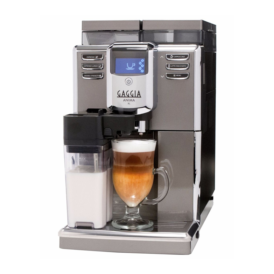
Gaggia Anima Service Manual
Hide thumbs
Also See for Anima:
- Operating instructions manual (92 pages) ,
- Operating instructions manual (72 pages) ,
- Operating instructions manual (88 pages)
Table of Contents
Advertisement
Coff ee Machine
Service
Service
Service
Service
General Information
Description
Housing material
Size (w x h x d) Anima OTC AMF CMF
Size (w x h x d) Anima XL
Weight OTC AMF CMF
Weight Anima XL
Power cord length
Control panel
Cup size
Water tank OTC AMF CMF
Water tank Anima XL
Coffee bean hopper capacity Anima OTC AMF CMF 250 g
Coffee bean hopper capacity Anima XL
Coffee grounds drawer capacity
Milk carafe capacity
Pump pressure
Boiler
Safety devices
Energy saving mode
Nominal voltage - Power rating - Power supply
All parts of this document are the property of Philips.
All rights reserved. Th is document and all the information herein is provided without liability deriving from any errors or omissions. Furthermore, no part may be reproduced, used or
collected, except where express authorisation has been provided in writing or through a contractual agreement.
Published by Philips
Service
Service
Value
Thermoplastic type
221 x 340 x 430 mm
221 x 386 x 430 mm
7,5 kg
8 kg
800 - 1200 mm
Front type
Up to 152 mm
1.8 litres - Removable type
2.5 litres - Removable type
500 g
15
0,5 l (OTC version)
15 bar
Stainless steel boiler
Thermal fuse
< 1 Wh
Read the data plate placed inside the service door
Subject to modifi cation
Gaggia Anima
Manual
Manual
(data may vary depending on the model)
(data may vary depending on the model)
Rev. 00 July 2015
EN 4219 400 00033
2015-July-30
Advertisement
Table of Contents

Related Manuals for Gaggia Anima


Summary of Contents for Gaggia Anima
- Page 1 Description Value Housing material Thermoplastic type Size (w x h x d) Anima OTC AMF CMF 221 x 340 x 430 mm (data may vary depending on the model) Size (w x h x d) Anima XL 221 x 386 x 430 mm...
-
Page 2: Table Of Contents
Service Policy 1.6.1. External machine parts Anima XL Disassembly 1.6.2. External machine parts Anima OTC 7.1. Outer Shell 1.6.3. External machine parts Anima AMF - CMF 1.6.4. Internal machine parts 7.2. Dispenser 7.3. Coff ee grinder Technical specifi cations 7.4. - Page 3 CHAPTER 1 INTRODUCTION GAGGIA ANIMA...
-
Page 4: Introduction
GAGGIA ANIMA 01 INTRODUCTION Documentation required The following documentation is needed for repair procedures: • Instruction booklet for specifi c model • Technical documentation for specifi c model (diagrams, exploded view, sympton cure and service manual) Tools and equipment required As well as the standard equipment, the following is required: Qty. -
Page 5: Service Policy
GAGGIA ANIMA 01 INTRODUCTION Water Flowmeter Two-way solenoid valve Two-way solenoid valve Flowmeter Image 1 Hot water /steam From this point circuit in pressure From this point circuit High temperaure Steam and hot water Steam pipe Water tank Water tank... -
Page 6: External Machine Parts Anima Xl
GAGGIA ANIMA 01 INTRODUCTION 1.6.1. External machine parts Anima XL Main components STAND-BY button Water tank seat Coffee bean hopper Removable water tank Main switch I. ON 0. OFF Power cord socket Coffee grounds drawer Drip tray Drip tray grill... -
Page 7: External Machine Parts Anima Otc
GAGGIA ANIMA 01 INTRODUCTION 1.6.2. External machine parts Anima OTC STAND-BY button Water tank seat Main components Coffee bean hopper Pre-ground coffee compartment Removable water tank Main switch I. ON 0. OFF Power cord socket Coffee grounds drawer Drip tray... - Page 8 GAGGIA ANIMA 01 INTRODUCTION 1.6.3. External machine parts Incanto AMF CMF STAND-BY button Main components Water tank seat Coffee bean hopper Pre-ground coffee compartment Removable water tank Main switch I. ON 0. OFF Power cord socket Coffee grounds drawer Drip tray...
-
Page 9: Internal Machine Parts
GAGGIA ANIMA 01 INTRODUCTION 1.6.4 Internal machine parts Power board Pump Thermostat Boiler Flow-meter Grinding adjustment insert Coffee grinder Safety valve 2-way solenoid valve Coffee dispenser Boiler pin Pag. 6/6... -
Page 10: Technical Specifi Cations
CHAPTER 2 TECHNICAL SPECIFICATIONS GAGGIA ANIMA... - Page 11 221 x 340 x 430 mm (Anima OTC AMF CMF) (data may vary depending on the model) Dimensions: W x H x D in mm: 221 x 386 x 430 mm (Anima XL) 7.5kg (Anima OTC AMF CMF) (data may vary depending on the model)
- Page 12 GAGGIA ANIMA 02 TECHNICAL SPECIFICATIONS 2.2.1. Specifi cation for the measurement of the coffee products temperature. The temperature is infl uenced by the fl ow from the dispenser and stratifi cation of temperatures in the glass. In order to consider these phenomena and to introduce measures that allow comparisons...
- Page 13 GAGGIA ANIMA 02 TECHNICAL SPECIFICATIONS 2.2.2. Specifi cation for the measurement of the Milk products temperature. Milk evaluation To carry out the test, a partially skimmed UHT milk with a percentage of grease between 1.5-1.8% at a refrigerator temperature Trefr. (between 4 to 10°C) must be used.
- Page 14 GAGGIA ANIMA 02 TECHNICAL SPECIFICATIONS How to measure the milk cream. The temperature (Trefr or Tamb) of the milk doesn’t affect as much the test result on measuring the milk cream; by convection is assumed to always use milk at refrigerator temperature Trefr..
-
Page 15: Machine Parameters And Performance
GAGGIA ANIMA 02 TECHNICAL SPECIFICATIONS 2.3. Machine parameters and performance Programm. by PRODUCT Default quantity User Production / QUANTITY (Grams) programmable Service Espresso 40 +/- 10gr Espresso lungo 120 +/- 14% Hot water Continues until the water supply has been exhausted (capacitive sensor) -
Page 16: User Instructions
CHAPTER 3 USER INSTRUCTIONS GAGGIA ANIMA... -
Page 17: Customer Menu
GAGGIA ANIMA 03 USER INSTRUCTIONS 3.1. Customer menu List of default settings Display Setting Setting Value Description COFFEE Coffee Coffee brewing temperature set- average TEMP temperature ting. 180° 60° STANDBY Stand-by 15 minu- 30° Stand-by time setting. time 15° DISPLAY... - Page 18 GAGGIA ANIMA 03 USER INSTRUCTIONS Reset to the default settings It is possible to restore the default settings through the programming menu. The machine must be turned on and ready to work. Press the MENU button and scroll through functions list to select the >...
-
Page 19: Operation, Cleaning And Maintenance
GAGGIA ANIMA 03 USER INSTRUCTIONS The machine is out of service Red Display If the machine error alarm signal is triggered, the error code is displayed in the bottom right corner of the display. (Following table) Error Behaviour Cause Action... -
Page 20: Operating Logic
CHAPTER 4 OPERATING LOGIC GAGGIA ANIMA... -
Page 21: Water Circuit
GAGGIA ANIMA 04 OPERATING LOGIC 4.1. Water circuit Pag. 1/10... -
Page 22: Milk Carafe
GAGGIA ANIMA 04 OPERATING LOGIC 4.2. Milk Carafe 1) Steam input 2)Bring the cappuccino maker into dispensing position 3) Milk tank The milk is heated by the steam and taken towards the emulsion chamber Steam where it is mixed with... -
Page 23: Single Microswitch
GAGGIA ANIMA 04 OPERATING LOGIC 4.3. Single microswitch Switching on When the machine is switched on, the gear motor repositions itself as follows: - It acts on microswitch 1 - The gear motor changes its rotation direction and moves upwards again by approx. 1-2 mm. -
Page 24: Coff Ee Grinder
GAGGIA ANIMA 04 OPERATING LOGIC 4.5. Coffee grinder only for 120v The coffee grinder is activated by a direct current motor (1) via helicoidal wheel transmission and a worm screw (2). The worm screw (2) activates a plastic toothed wheel (3), which turns the lower grinder blade (4) and the increment pin (5). -
Page 25: Dose Self-Learning (Sas) Only For 120V
GAGGIA ANIMA 04 OPERATING LOGIC 4.7. Dose self-learning (SAS) only for 120v The aim of this function is to automatically regulate the average dose of ground coffee (SELF- LEARNING); this takes place with an algorithm based on the following values and setting by the user: 1. -
Page 26: Coffee Grinder
GAGGIA ANIMA 04 OPERATING LOGIC 4.8. Coffee grinder The coffee grinder is driven by a direct current motor (1) using a worm screw helicoidal wheel transmission (2). The worm screw (2) drives a plastic gear wheel (3), which turns the lower grinder (4) and the increment pin (5) 4.9. -
Page 27: Coff Ee Lack Detection And Coff Ee Grinder Blocked. 7
GAGGIA ANIMA 04 OPERATING LOGIC 1) When the system get the stability (i.e. the system got the current target) the coffee doses should be: A2/3 A4/5 ±1,5 grams with medium grinding (500±60μm) and using coffee of test. 2) the 3 grinding times are always: <T... -
Page 28: Coffee Cycle
GAGGIA ANIMA 04 OPERATING LOGIC 4.11. Coffee cycle Main switch ON START STOP Time Coffee grinder Time (Dosage) Heating approx. 45 sec. Pump Pump operation (fl ow meter pulses) in accordance with the amount of product selected. Brewing unit gear... -
Page 29: Water Level Detection (Water Tank)
GAGGIA ANIMA 04 OPERATING LOGIC 4.12. Water level detection (water tank) “Water low” message (water reserve) Function: The water level is monitored by a capacitative sensor, located one Water tank third of the way up the water tank wall. If the electronics assembly detects, by means of the sensor,... -
Page 30: Water Fi Lter
GAGGIA ANIMA 04 OPERATING LOGIC 4.14. Water fi lter Function: • Reduced limescale deposits which take longer to form. • Improved water quality. • Improved taste due to the ideal water hardness. Life span / descaling performance: • - 10 ° dH •... -
Page 31: Troubleshooting
CHAPTER 5 TROUBLESHOOTING GAGGIA ANIMA... -
Page 32: Test Mode Incanto
5.1. Test Mode Introduction This document describes the Test Mode of the Anima (CMF,AMF, OTC and XL) Coffee Machine. This application is used in order to test the machine in its mechanics and electronic components. To enter Test Mode The machine enters in Test mode by holding pressed together Z1 and Z6 buttons while switching on the machine by the main switch on the backside of the CA. - Page 33 GAGGIA ANIMA 05 TROUBLESHOOTING Page 5: High voltage loads test (Heater , Grinder ): a) Heater (230V AC) b) Grinder (320V DC) The user can change the page by pressing the Z7 button. Page 0 is accessible only entering Test Mode from power-off mode; at the start up all loads are turned off.
- Page 34 GAGGIA ANIMA 05 TROUBLESHOOTING Page 1 (KEYBOARD) Page 1 (KEYBOARD) Start condition Start condition Press buttons from 1 to 7 Press buttons from 1 to 7 Only when a button is pressed a O appears on the relative position of button pressed.
- Page 35 GAGGIA ANIMA 05 TROUBLESHOOTING Insert the BrewUnit Insert the BrewUnit The indications The indications BU-P BU-P changes from “N” to “Y”. changes from “N” to “Y”. Note: Note: removing the BrewUnit the indication from “Y” to “N” requires removing the BrewUnit the indication from “Y” to “N” requires about 2-3 seconds to switch.
- Page 36 GAGGIA ANIMA 05 TROUBLESHOOTING ERROR: ERROR: (With BU) (With BU) The absorbed current is more than 300mA, The absorbed current is more than 300mA, the display backlight changes from white to red; check the BU and the display backlight changes from white to red; check the BU and...
- Page 37 GAGGIA ANIMA 05 TROUBLESHOOTING It is possible to hear the “click” from Electro Valve. The indication It is possible to hear the “click” from Electro Valve. The indication beside the beside the EV1 EV1 changes from “OFF” to “ON”. changes from “OFF” to “ON”.
-
Page 38: Steamout
GAGGIA ANIMA 05 TROUBLESHOOTING ERROR: ERROR: In the indication In the indication HEATER HEATER appears appears “OPEN” “OPEN”, the , the NTC temperature-sensor is detached or broken, the display backlight temperature-sensor is detached or broken, the display backlight changes from white to red; check the wiring from the NTC changes from white to red;... - Page 39 GAGGIA ANIMA 05 TROUBLESHOOTING IMPORTANT NOTE: to execute the Steam-Out procedure the DREGDRAWER must be in place and the DOOR must be closed. If these 2 conditions are not respected a warning message is shown on the display and the Steam-Out is interrupted.
-
Page 40: Error Codes
GAGGIA ANIMA 05 TROUBLESHOOTING 5.2. Error codes ERROR ERROR DESCRIPTION DESCRIPTION CODES CODES The coffee grinder is blocked The grinder is disconnected The brewing unit is blocked in work position The brewing unit is blocked in home position The hydraulic circuit is clogged... -
Page 41: Standard Checks
CHAPTER 6 STANDARD CHECKS GAGGIA ANIMA... -
Page 42: Repair Schedule
GAGGIA ANIMA 06 STANDARD CHECKS 6.1. Repair schedule Action Visual inspection (transport damage) Machine data check (rating plate) Operational check / problem analysis Opening machine Visual inspection Operational tests Repairing the faults encountered Checking any modifi cations (view Symptom Cure, new software, etc.) -
Page 43: Final Test
GAGGIA ANIMA 06 STANDARD CHECKS 6.3. Final test Support/ Test Procedure Standard Tolerance tool 2-3 Espressos for Measuring Espresso Same amount adjustment purposes scoop 2-3 Coffees for Measuring Coffee Same amount adjustment purposes scoop Noise Standard The cream should Amount of... -
Page 44: Disassembly
CHAPTER 7 DISASSEMBLY GAGGIA ANIMA... -
Page 45: Outer Shell
GAGGIA ANIMA 07 DISASSEMBLY 7.1. Outer Shell Anima OTC Anima XL Remove the water tank, coffee container cover, drip tray, dreg drawer, brewing unit. Remove the cover as in the Upper cover photo. In case of any issues please you can try with the alternative way below de- scribed. -
Page 46: Dispenser
GAGGIA ANIMA 07 DISASSEMBLY Unscrew the screws shown Remove the insert the upper cover Remove the support KYB assy. Remove the upper cover and remove the electrical and and disconnect the fl at cable. water circuit connections. remove the block support KYB assy. -
Page 47: Coffee Grinder
GAGGIA ANIMA 07 DISASSEMBLY 7.3. Coffee grinder When reassembling the coffee grinder, make sure the spring is Raise the coffee grinder and remove the connections. repositioned correctly (see photo). 7.4. Grinder blades To extract the top support of the appliance, press on the grinding adjustment spindle (A) and turn the support anticlockwise until it unhooks. -
Page 48: Coffee Grinder Adjustment
GAGGIA ANIMA 07 DISASSEMBLY For a standard adjustment, both markings must be aligned. 7.5. Coffee grinder adjustment The grinding adjustment can be set by the user (only with the coffee grinder in operation) by pressing and turning (only by one click at a time) the insert inside the coffee bean hopper with the aid of the wrench supplied. -
Page 49: Carafe Connection And Hot/Steam Water Dispenser
GAGGIA ANIMA 07 DISASSEMBLY 7.6. Carafe connection and hot/steam water dispenser Slide out the fork Loosen the screws holding When reassembling the assembly to be as illustrated the carafe connection careful to correctly position the spring. hot water dispenser unscrew the screws... -
Page 50: Pin Boiler
GAGGIA ANIMA 07 DISASSEMBLY 7.8. Pin boiler Loosen the screws as illustrated and remove the boiler pin (A). 7.9. Gear motor Loosen the screws as illustrated and remove the gear motor cover. The following are located inside the compartment protected... -
Page 51: Pump
GAGGIA ANIMA 07 DISASSEMBLY 7.10. Pump Unhook the pump Disconnect the water circuit connections (A) and from the supports. electrical connections (B), loosen the safety valve (C) and slide the pump off the brackets (D). 7.11. Flow-meter Lift the fl ow meter out of the casing assembly and remove the electrical and water circuit connections. -
Page 52: Cpu Board
GAGGIA ANIMA 07 DISASSEMBLY 7.13. CPU board Loosen the screws slide the card off the support and disconnect the electrical connections. 7.14. Programming access for SSC (Saeco Service Center) Loosen the screw for remove the cover. 7.15. KYB interface and display Remuve the cap, unscrew the screw shown and remove the steam tube. -
Page 53: Fitting And Removing Oetiker Clamps
GAGGIA ANIMA 07 DISASSEMBLY Loosen the screws for remove the cover. Remove the support KYB assy. Disconnect the electrical and disconnect the fl at cable. connections. 7.16. Fitting and removing Oetiker clamps 1) Boiler connection. 2) Other connections. Use a suitable pair of pliers to remove Tighten the clamp as illustrated. -
Page 54: Notes
CHAPTER 8 NOTES GAGGIA ANIMA... - Page 55 GAGGIA ANIMA 08 NOTES Pag. 1/1...
-
Page 56: Water Circuit Diagram
CHAPTER 9 WATER CIRCUIT DIAGRAM GAGGIA ANIMA... - Page 57 GAGGIA ANIMA 09 WATER CIRCUIT DIAGRAM Pag. 1/1...
-
Page 58: Electrical Diagram
CHAPTER 10 ELECTRICAL DIAGRAM GAGGIA ANIMA... - Page 59 GAGGIA ANIMA 10 WIRING DIAGRAM Pag. 1/1...