Pro-Form performance 650 User Manual
Hide thumbs
Also See for performance 650:
- User manual (16 pages) ,
- User manual (16 pages) ,
- User manual (16 pages)
Table of Contents
Advertisement
Model No. PETL80911.0
Serial No.
Write the serial number in the space
above for reference.
Serial Number
Decal
QUESTIONS?
UNITED KINGDOM
Call: 08457 089 009
From Ireland: 053 92 36102
Website: www.iconsupport.eu
E-mail: csuk@iconeurope.com
Write:
ICON Health & Fitness, Ltd.
c/o HI Group PLC
Express Way
CASTLEFORD
WF10 5QJ
UNITED KINGDOM
AUSTRALIA
Call: 1800 993 770
E-mail: australiacc@iconfitness.com
Write:
ICON Health & Fitness
PO Box 635
WINSTON HILLS NSW 2153
AUSTRALIA
CAUTION
Read all precautions and instruc-
tions in this manual before using
this equipment. Save this manual
for future reference.
USER'S MANUAL
www.iconeurope.com
Advertisement
Table of Contents

Related Manuals for Pro-Form performance 650


Summary of Contents for Pro-Form performance 650
- Page 1 Model No. PETL80911.0 Serial No. USER’S MANUAL Write the serial number in the space above for reference. Serial Number Decal QUESTIONS? UNITED KINGDOM Call: 08457 089 009 From Ireland: 053 92 36102 Website: www.iconsupport.eu E-mail: csuk@iconeurope.com Write: ICON Health & Fitness, Ltd. c/o HI Group PLC Express Way CASTLEFORD...
-
Page 2: Table Of Contents
TABLE OF CONTENTS WARNING DECAL PLACEMENT ............. . .2 IMPORTANT PRECAUTIONS . -
Page 3: Important Precautions
IMPORTANT PRECAUTIONS WARNING: To reduce the risk of burns, fire, electric shock, or injury to persons, read all important precautions and instructions in this manual and all warnings on your treadmill before using your treadmill. ICON assumes no responsibility for personal injury or property damage sus- tained by or through the use of this product. - Page 4 DANGER: 21. Do not attempt to move the treadmill until it Always unplug the power is properly assembled. (See ASSEMBLY on cord immediately after use, before clean- page 7, and HOW TO FOLD AND MOVE THE ing the treadmill, and before performing the TREADMILL on page 19.) You must be able to maintenance and adjustment procedures safely lift 45 lbs.
-
Page 5: Before You Begin
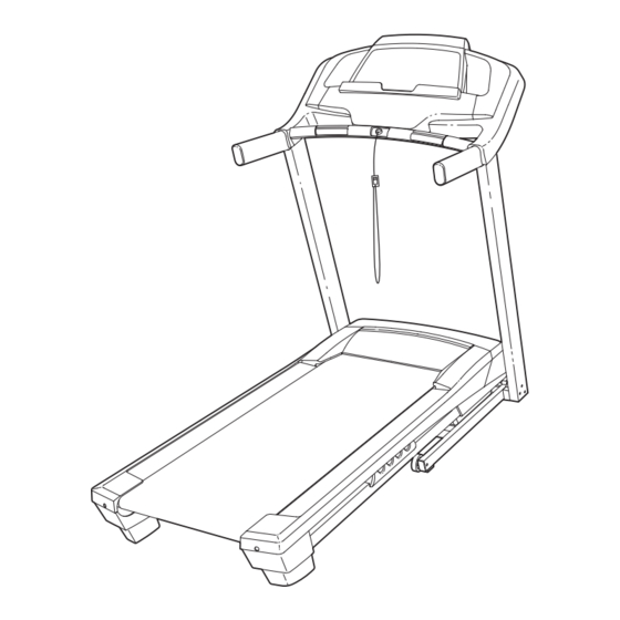
Thank you for selecting the new PROFORM reading this manual, please see the front cover of this ® PERFORMANCE 650 treadmill. The PERFORMANCE manual. To help us assist you, note the product model 650 treadmill provides an impressive selection of fea- number and serial number before contacting us. -
Page 6: Part Identification Chart
PART IDENTIFICATION CHART Use the drawings below to identify small parts used for assembly. The number in parentheses below each draw- ing is the key number of the part, from the PART LIST near the end of this manual. The number following the key number is the quantity used for assembly. -
Page 7: Assembly
ASSEMBLY • Assembly requires two persons. • To identify small parts, see page 6. • Place all parts in a cleared area and remove the • Assembly requires the following tools: packing materials. Do not dispose of the packing the included hex keys materials until you finish all assembly steps. - Page 8 2. Identify the Left Upright (78). Have a second person hold the Left Upright near the Base (86). See the inset drawing. Tie the wire tie in the Wire Left Upright (78) securely around the end of the Upright Wire (77). Then, insert the Upright Wire into the lower end of the Left Upright as you pull the other end of the wire tie upward through the Wire...
-
Page 9: Handrail
4. Identify the Left Handrail (74). Remove the tie from the 5/16" Cage Nut (34). If necessary, press the Cage Nut back into place. Hold the Left Handrail (74) near the Left Upright (78). Insert the Upright Wire (77) through the bracket on the bottom of the Left Handrail. - Page 10 6. IMPORTANT: To avoid damaging the Crossbar (80), do not use power tools and do not overtighten the #8 x 3/4" Silver Screws (2). Orient the Crossbar (80) as shown. Attach the Crossbar to the Handrails (74, 75) with four #8 x 3/4"...
- Page 11 8. Set the console assembly on the Left Handrail (74) and the Right Handrail (75). Be careful Console not to pinch any wires. Pull the plastic tie tight Assembly around the Upright Wire (77) and cut off the end of the tie. Insert the excess Upright Wire into the Left Handrail.
- Page 12 10. Raise the Frame (55) to the position shown. Have a second person hold the Frame until step 11 is completed. Orient the Storage Latch (56) so that the large barrel and the latch knob are oriented as shown. Attach the lower end of the Storage Latch (56) to the Base (86) with a 3/8"...
-
Page 13: Operation And Adjustment
OPERATION AND ADJUSTMENT HOW TO PLUG IN THE POWER CORD Follow the steps below to plug in the power cord. This product must be earthed. If it should malfunc- 1. Plug the indicated end of the power cord into the tion or break down, earthing provides a path of least socket on the treadmill. - Page 14 CONSOLE DIAGRAM FEATURES OF THE CONSOLE Note: The console can display speed and distance in either miles or kilometers. To find which unit of mea- The treadmill console offers a selection of features surement is selected, see THE INFORMATION MODE designed to make your workouts more effective and on page 18. For simplicity, all instructions in this man- enjoyable.
-
Page 15: To Turn On The Power
HOW TO TURN ON THE POWER HOW TO USE THE MANUAL MODE IMPORTANT: If the treadmill has been exposed to 1. Insert the key into the console. cold temperatures, allow it to warm to room tem- perature before turning on the power. If you do not See HOW TO TURN ON THE POWER at the left. - Page 16 4. Change the incline of the treadmill as desired. To reset the display, press the Stop button, remove the key, and then reinsert the key. To change the incline of the treadmill, press the 6. Measure your heart rate if desired. Incline increase or decrease button or one of the Quick % Grade buttons numbered 0 through 10.
- Page 17 HOW TO USE AN ONBOARD WORKOUT The workout will continue in this way until the last segment of the profile flashes in the display and the 1. Insert the key into the console. last segment ends. The walking belt will then slow to a stop. See HOW TO TURN ON THE POWER on page 15. Note: The calorie goal is an estimate of the 2.
- Page 18 THE INFORMATION MODE • A n “E” for English miles or an “M” for metric kilome- ters. To change the unit of measurement, press the The console features an information mode that keeps Speed increase button. track of treadmill usage information. The information mode also allows you to select miles or kilometers as • A “d”...
-
Page 19: How To Fold And Move The Treadmill
HOW TO FOLD AND MOVE THE TREADMILL HOW TO FOLD THE TREADMILL HOW TO MOVE THE TREADMILL To avoid damaging the treadmill, adjust the incline Before moving the treadmill, fold it as described at the to the lowest position before you fold the treadmill. left. -
Page 20: Troubleshooting
TROUBLESHOOTING Most treadmill problems can be solved by following c. Remove the key from the console, and then the simple steps below. Find the symptom that reinsert it. applies, and follow the steps listed. If further assis- tance is needed, see the front cover of this manual. d. - Page 21 Lower the treadmill (see HOW TO LOWER THE recalibrate the incline system. If the incline does not TREADMILL FOR USE on page 19). Remove begin calibrating, press the Stop button again, and the three #8 x 3/4" Screws (1). Carefully slide the then press the Incline increase or decrease button Motor Hood (59) off.
- Page 22 SYMPTOM: The walking belt is not centered SYMPTOM: The walking belt slips when walked on between the foot rails. IMPORTANT: If the walking belt rubs against the foot rails, the walking belt a. First, remove the key and UNPLUG THE POWER may be damaged.
-
Page 23: Exercise Guidelines
EXERCISE GUIDELINES Burning Fat—To burn fat effectively, you must exer- WARNING: cise at a low intensity level for a sustained period of Before beginning this time. During the first few minutes of exercise, your or any exercise program, consult your physi- body uses carbohydrate calories for energy. - Page 24 SUGGESTED STRETCHES The correct form for several basic stretches is shown at the right. Move slowly as you stretch —never bounce. 1. Toe Touch Stretch Stand with your knees bent slightly and slowly bend forward from your hips. Allow your back and shoulders to relax as you reach down toward your toes as far as possible.
- Page 25 NOTES...
- Page 26 NOTES...
-
Page 27: Part List
PART LIST Model No. PETL80911.0 R0912A Key No. Qty. Description Key No. Qty. Description #8 x 3/4" Screw Drive Motor Belt #8 x 3/4" Silver Screw Drive Motor 5/16" x 1" Bolt Filter 1/4" x 1/2" Screw Filter Bracket 3/8" x 2" Bolt Frame 3/8"... -
Page 28: Exploded Drawing
EXPLODED DRAWING A Model No. PETL80911.0 R0912A... - Page 29 EXPLODED DRAWING B Model No. PETL80911.0 R0912A...
- Page 30 EXPLODED DRAWING C Model No. PETL80911.0 R0912A...
- Page 31 EXPLODED DRAWING D Model No. PETL80911.0 R0912A...
-
Page 32: Ordering Replacement Parts
ORDERING REPLACEMENT PARTS To order replacement parts, please see the front cover of this manual. To help us assist you, be prepared to pro- vide the following information when contacting us: • the model number and serial number of the product (see the front cover of this manual) • the name of the product (see the front cover of this manual) • the key number and description of the replacement part(s) (see the PART LIST and the EXPLODED DRAWING near the end of this manual)