Sign In
Upload
Manuals
Brands
Ziatech Corporation Manuals
Motherboard
ZT 8808A
Ziatech Corporation ZT 8808A Computer Manuals
Manuals and User Guides for Ziatech Corporation ZT 8808A Computer. We have
1
Ziatech Corporation ZT 8808A Computer manual available for free PDF download: Operating Manual
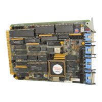
Ziatech Corporation ZT 8808A Operating Manual (412 pages)
V20 Single Board Computer
Brand:
Ziatech Corporation
| Category:
Motherboard
| Size: 1.07 MB
Table of Contents
Table of Contents
7
Chapter 1 . INTRODUCTION
18
Introduction
18
Overview
18
ZT 88CT08A and ZT 88CT09A
20
Features of the Zt 8809A
21
Figure 1-1 ZT 8809A Functional Block Diagram
22
Functional Blocks
23
Memory and I/O Addressing
23
V20 (Upd70108) Processor
23
Direct Memory Access (DMA)
24
Optional Battery Backup
24
Wait-State Generator
24
AC/DC Power-Fail Detection
25
Real-Time Clock
26
Serial Communications
26
Counter/Timers
27
Interrupts
28
Centronics Printer/General Purpose I/O Port
29
Optional Numeric Data Coprocessor (8087)
29
Clock Slowdown & Halt Restart (CMOS Boards Only)
30
Getting Started
31
Chapter 2 GETTING STARTED
31
Overview Unpacking What's in the Box? System Requirements
31
Table A-2 Memory Addressing
31
Overview
32
Physical Requirements
34
Power Requirements
34
Environmental Requirements
36
Installing the Zt 8809A
37
Figure 2-1 Non-DOS Factory Default Jumper Configuration
38
Configuring the ZT 8809A for STD ROM
39
STD ROM Memory Requirements
39
STD ROM Cable Requirements
40
STD ROM Jumper Configuration
40
Powering up STD ROM
41
Configuring the ZT 8809A for STD DOS
43
Figure 2-2 ZT 8809A Configured for STD DOS
44
STD DOS Memory Requirements
45
STD DOS Cable Requirements
46
STD DOS Jumper Configuration
46
Powering up STD DOS
47
Memory Addressing
49
Figure 2-3 STD DOS Factory Default Memory Map
50
Figure 2-4 STD ROM Factory Default Memory Map
51
I/O Addressing
52
Figure 2-5 I/O Map, STD DOS / STD ROM Systems
53
Upgrading from Zt 8806/8807 Systems
54
Theory of Operation
56
Chapter 3 . THEORY of OPERATION
57
Overview
57
Relative Microprocessor Performance
58
Memory and I/O
59
Serial Communications
59
Serial Port 1 (COM1)
60
Serial Port 2 (COM2)
61
Theory of Operation
62
Std Bus Compatibility
59
Interrupts
63
Interrupt Request Assignments
63
Figure 3-1 PIC Interrupt Input Requests
64
Polled Interrupts on the STD Bus
65
Figure 3-2 Polled Interrupt Structure
66
Figure 3-3 Small Scale Vectored Structure
67
STD Bus Vectored Interrupts
67
Figure 3-4 Large Scale Vectored Structure
68
STD Bus Cascaded Interrupts
68
Non-Maskable Interrupts
69
Direct Memory Access (Dma)
70
Advantages of DMA
70
DMA Operation
71
Figure 3-5 DMA with STD Bus Controller
72
Power-Fail Protection
73
DC Power-Fail
73
AC Power-Fail
74
Figure 3-6 AC Transformer Connection
74
System Battery Fail
77
Battery
78
Status Indicator (Led)
80
Reset
81
Added Features
82
Cmos Versions of the Zt 8808A/8809A
82
Functional Differences
84
Application Examples
85
Chapter 4. APPLICATION EXAMPLES
85
Overview
86
Example 1-A: Using Simple Interrupts
87
Objectives
87
System Configuration
87
Software Outline
88
Program Code
90
Example 1-B: Handling Slave Interrupts
97
Objectives
97
Software Outline
98
System Configuration
98
Program Code
101
Example 2: Power-Fail/Watchdog Timer
112
Objectives
112
System Level Issues
112
System Requirements
113
Software Outline
115
Flowcharts for AC Power-Fail & Watchdog Interrupts
118
Example 3: Real-Time Clock Drivers
124
Objectives
124
Software Outline
124
System Configuration
124
Memory and I\/O Capability
126
Chapter 5. MEMORY and I/O CAPABILITY
126
Overview Memory Addressing
126
Memory Expansion (MEMEX)
126
Memory Addressing
127
On-Board Memory Capacity
127
Write Protection
128
Figure 5-1 STD DOS Factory Default Memory Map
129
Memory Maps
129
Figure 5-2 STD DOS Factory Default Jumper Configuration
130
Figure 5-3 STD DOS Map with 640K On-Board RAM
131
Figure 5-4 STD DOS with 640K RAM Jumper Configuration
132
Figure 5-5 Non-DOS Factory Default Memory Map
133
Figure 5-6 Non-DOS Factory Default Jumper Configuration
134
Battery Backup
135
Figure 5-7 Memory Chip Locations
136
Sockets 3D1 and 5D1
137
Sockets 7D1 and 9D1
138
Device Access Times
139
Table 5-3 Device Access Times
139
Input/Output Addressing
140
Figure 5-8 ZT 8809A I/O Map
141
CPU Description (V20)
142
Table 6-1 Segment Registers
142
Chapter 6. CPU DESCRIPTION (V20)
143
Memory Device Locations
136
V20 Overview
143
Segment Registers
144
Program Counter (PC) [IP]
146
General Purpose Registers
147
Prefetch Pointer (PFP)
147
Pointers and Index Registers
148
Figure 6-1 Program Status Word
149
Program Status Word (PSW) [FL]
149
V20 Architectural Enhancements
150
Dual Data Bus
150
Effective Address Generator
150
16/32-Bit Temporary Shift Registers (TA,TB)
151
Loop Counter (LC)
151
Program Counter (PC) and Prefetch Pointer (PFP)
151
Enhanced and Unique Instructions
152
Mode Operations - 8080 Emulation Mode
153
Figure 6-2 V20 Modes
154
Break for Emulation (BRKEM)
155
Return from Emulation (RETEM)
155
Call Native Routine (CALLN)
156
Return from Interrupt (RETI)
156
Register Use in Emulation Mode
157
Dma Support
159
Figure 6-3 DMA with STD Bus Controller
160
Reset State
161
Wait-State Generator
162
Numeric Data Processor (8087)
163
Chapter 7 . NUMERIC DATA PROCESSOR (8087)
163
Overview
163
Zsbc 337 PIGGYBACK PROCESSOR INSTALLING the Zsbc
163
Installing the Zsbc 337
166
Figure 7-1 Zsbc 337 Piggyback Processor Installation
168
Coprocessor Interface
169
Memory Addressing
170
Interrupt/Numeric Errors
171
References
175
Serial Communications (16C452)
176
Chapter 8. SERIAL COMMUNICATIONS (16C452)
176
Overview
176
Serial Communications Protocol Serial Interface (Rs-232-C/422/485)
176
RS-232-C Vs. RS-422/485
176
Figure 8-1 Establishing Serial Communications
180
Figure 8-2 Loopback of RTS/CTS, DTR/DSR
182
Serial Interface (Rs-232-C/422/485)
183
Figure 8-3 16C452 Serial Port Block Diagram
184
Clear-To-Send Inputs (CTS0*, CTS1*)
186
Data-Set-Ready (DSR0*, DSR1*)
186
Signal Definitions
186
Data-Terminal-Ready (DTR0*, DTR1*)
187
Serial Channel Interrupt Outputs (INT0, INT1)
187
Receive Line Signal Detect (RLSD0*, RLSD1*)
188
Ring Indicator Inputs (RI0*, RI1*)
188
Reset Control (RESET*)
189
Table 8-1 16C452 Reset State
189
Request-To-Send (RTS0*, RTS1*)
190
Serial Data Inputs (SIN0, SIN1)
190
Serial Data Outputs (SOUT0, SOUT1)
190
Serial Registers
191
Table 8-2 ZT 8809A I/O Port Assignments
192
Table 8-3 16C452 Addressable Registers Summary
193
Scratchpad Register
195
Transmit and Receive Buffer Registers
195
Line Control Register
196
Baud Rate Generator
199
Table 8-4 Baud Rate Table
200
Line Status Register
201
Interrupt ID Register
203
Table 8-5 16C452 Interrupt Control Functions
204
Interrupt Enable Register
205
Modem Control Register
206
Modem Status Register
208
Centronics Printer Interface
210
Chapter 9. CENTRONICS PRINTER INTERFACE
210
Overview
210
Figure 9-1 Printer Interface Block Diagram
211
Printer Port Output Characteristics
212
Using the Printer Port
213
Register Definitions/Addresses
214
Table 9-2 Parallel Port Register Definitions
214
Table 9-3 Parallel Port Register Addresses
214
Data Port
215
Status Port
216
Control Port
217
Interrupt Capability
218
Shared Signals
219
Disabling Sharing of Printer Port Signals
221
Optional Printer Cable Pinout
223
Table 9-5 ZT 90039 Cable Pinout
223
Printer Port Reset State
224
Chapter 11 . COUNTER/TIMERS (8254)
225
Overview Operation
225
Figure 10-1 Real-Time Clock Block Diagram
226
Chapter 10 . REAL-TIME CLOCK (DS 1215)
229
Figure 10-2 Timechip Comparison Register
229
Timechip Comparison Register Definition
229
Timekeeper Register Information
230
Figure 10-3 Timechip Register
231
AM/PM 12/24-Hour Mode
232
Oscillator and Reset Bits
232
Zero Bits
232
Timechip Register Definition
231
Counter/Timers (8254)
233
Overview Block Diagram Counter/Timer Architecture Operation
233
Overview
234
Figure 11-1 Intel 8254 Timers Block Diagram
235
Block Diagram
235
Figure 11-2 Internal Block Diagram of a Counter
236
Counter/Timer Architecture
236
Reset State
238
Programming
238
Operation
238
Read Operations
240
Counter Latch Command
240
Simple Read
240
Read-Back Command
243
Table 11-1 Read-Back Command Example
247
Mode Definitions
248
Mode 0: Interrupt on Terminal Count
248
Mode 1: Hardware Retriggerable One-Shot
249
Mode 2: Rate Generator
250
Mode 3: Square Wave Mode
251
Mode 4: Software Triggered Strobe
252
Mode 5: Hardware Triggered Strobe
253
Gate
255
Operation Common to All Modes
255
Programming
255
Counter
256
Table 11-3 Minimum and Maximum Initial Counts
256
Counter Use by STD DOS and STD ROM
257
Interrupt Controller (8259A)
258
Chapter 12. INTERRUPT CONTROLLER (8259A)
258
Overview I/O Port Addresses Operation Overview Functional Description
258
Interrupt Request Register (IRR)
258
I/O Port Addresses
260
Operation Overview
261
Functional Description
264
Interrupt Mask Register (IMR)
264
Interrupt Mask Register (IMR)
265
Control Logic
266
Interrupt In-Service Register (ISR)
266
Priority Resolver (PR)
266
Cascade Buffer/Comparator
267
Initialization and Operation Registers
267
Read/Write Control Logic
267
Programmable Registers
268
Table 12-1 PIC Registers
268
Icw1
269
Initialization Control Words (ICW1-4)
269
Icw2
271
Icw3
271
Icw4
272
ICW Summary
273
Operation Control Words (OCW1-3)
273
Ocw1
275
Ocw2
275
Ocw3
276
8259A I/O Port Addresses
278
Interrupt Assignments on the Zt 8809A
279
Operation of the Interrupt Controller
281
Automatic Rotating Mode
281
Fully Nested Mode
281
Poll Mode
281
Priorities
281
Special Fully Nested Mode
281
Special Mask Mode
281
Specific Rotating Mode
281
Interrupt Triggering
284
Level-Triggered Mode
285
Edge-Triggered Mode
286
Interrupt Status
286
Eoi Commands
288
Nonspecific EOI Commands
288
Automatic EOI Mode
289
Specific EOI Commands
289
When to Use Automatic EOI Mode
290
Reset
291
Zt 88Ct08A/88Ct09A Cmos Boards
292
Chapter 13. ZT 88CT08A/88CT09A CMOS BOARDS
292
Overview
292
Functional Differences
293
Logic Family (CT Vs. C)
293
Use of 80C88 Processor
294
Addition of Optional 8087(-2)
295
Clock Slowdown Mode
295
Halt with Restart Via Interrupt
297
Electrical/Environmental Differences
299
Increased Temperature Range
299
Reduced Power Consumption
299
Bus Loading
300
Appendix A. JUMPER CONFIGURATIONS
301
Overview
301
Table A-1 Jumper Descriptions
301
Jumper Descriptions
303
Specifications
357
Appendix B. SPECIFICATIONS
357
Overview
357
Specifications
357
Electrical and Environmental
358
Absolute Maximum Ratings
358
DC Operating Characteristics
358
Battery Backup Characteristics
359
STD Bus Loading Characteristics
359
Table B-1 STD Bus Signal Loading, P Connector
360
Table B-2 STD Bus Signal Loading, E Connector
361
Mechanical
362
Component Side
363
Mechanical Specifications
363
Connectors
365
Solder Side
367
Table B-4 J1 Pin Assignments (RS-232-C)
369
Table B-5 J2 Pin Assignments (RS-232-C)
370
Table B-6 J2 Pin Assignments (RS-422/485)
371
Table B-7 J3 Pin Assignments
372
Table B-8 J4 Pin Assignments
373
Timing
379
Appendix C. CUSTOMER SUPPORT
386
Overview
386
Customer Support
386
Troubleshooting
387
Powering up STD ROM
387
Powering up STD DOS
389
Zt 8808A/8809A Revision History
393
Revision 0 - Original Release of Board, 12/17/91
393
Revision a - 8/19/92
393
Zt 88Ct08A/88Ct09A Revision History
393
Reliability
394
Warranty
395
Technical Assistance
396
Returning for Service
397
Advertisement
Advertisement
Related Products
Ziatech Corporation ZT 8903
Ziatech Corporation ZT 8904
Ziatech Corporation ZT 89CT04
Ziatech Corporation ZT 8809A
Ziatech Corporation ZT 8906
Ziatech Corporation ZT 8905
Ziatech Corporation ZT 8907
Ziatech Corporation ZT 8825
Ziatech Corporation ZT 88CT25
Ziatech Corporation ZT 8995
Ziatech Corporation Categories
Motherboard
Recording Equipment
Video Card
Controller
Storage
More Ziatech Corporation Manuals
Login
Sign In
OR
Sign in with Facebook
Sign in with Google
Upload manual
Upload from disk
Upload from URL