Sign In
Upload
Manuals
Brands
York Manuals
Air Conditioner
Sun Premier GZA1M Series
York Sun Premier GZA1M Series Manuals
Manuals and User Guides for York Sun Premier GZA1M Series. We have
1
York Sun Premier GZA1M Series manual available for free PDF download: Start-Up & Operation
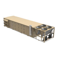
York Sun Premier GZA1M Series Start-Up & Operation (122 pages)
Rooftop Units
Brand:
York
| Category:
Air Conditioner
| Size: 5.72 MB
Table of Contents
Table of Contents
1
Nomenclature
4
Pre Start-Up Checklist
7
Figure 1: Trap Detail for Draw through Application
9
Start-Up
9
Long Term Storage
9
Checking System Prior to Initial Start (no Power)
9
Unit Checks (Power Applied)
10
Table 1: Component Static Pressure Drops (Iwg)
11
Table 2: 25-30 Ton Supply Fan Total Static Pressure
13
Table 3: 40-50 Ton Supply Fan Total Static Pressure
14
Table 5: 40-50 Ton Exhaust Fan Total Static Pressure
15
Table 6: 25-30 Ton Return Fan Total Static Pressure
15
Table 8: R-410A Pressure/Temperature Chart
17
Figure 2: Manifold Gas Pressure Adjustment
19
Table 9: Staged Gas Low Fire/High Fire Pressures
19
Table 10: Staged and Modulating Gas Heat
20
Table 11: Air Balancing Wizard Points
21
Start-Up Wizard
24
Table 12: Start-Up Wizard Signals
24
Start-Up Wizard Sequence
26
Control Boards
30
Sequences of Operation
30
Table 4: 25-30 Ton Exhaust Fan Total Static Pressure
14
Air Balancing Wizard
20
Commissioning Mode
20
Phase Monitor Adjustment
20
Table 7: 40-50 Ton Return Fan Total Static Pressure
15
Initial Start-Up
16
Checking Sub-Cooling and Superheat
16
Refrigerant Charge
16
Gas Heat Models
17
Leak Checking
17
Figure 3: Control Board Locations
30
Figure 4: User Interface Display Board
31
Figure 5: Main Control Board
31
Table 13: Main Control Board Field Terminal Points
31
Figure 6: Condenser Boards
32
Table 14: Condenser Boards Field Terminal Points
32
Table 15: Options Board Field Terminal Points
32
Figure 8: Building System Interface Board
33
Table 16: Building System Interface Board Field Terminal Points
33
Figure 9: Modulating Gas Heat Control Board
34
Figure 11: Field Wiring to Building System Interface Board
35
Figure 12: Field Wiring to Options Board
36
Figure 15: Seven VFD Cutout Display Panel
37
Table 17: VFD Field Parameters
37
Figure 16: Safety Switch Input
39
Redundant Supply Fan VFD
40
SZVAV Supply Fan
40
Figure 17: Condenser Fan/Compressor Locations
42
Figure 7: Options Board
32
Figure 13: Field Wiring to Main Control Board
36
Figure 14: Three VFD Cutout Display Panel
37
Cooling Operation
40
MZVAV Cooling Operation
40
Compressors and Refrigeration Circuits
42
SZVAV Cooling Operation
42
Table 18: Compressor Numbering
43
Table 19: Compressor Layout
43
Compressor Staging Sequences
44
Figure 18: Safety Chain Wiring
46
Figure 19: Low Pressure Cutout Switch Wiring
46
Table 20: Compressor Motor Protection
47
Table 21: Saturated Liquid Line Temperature Setpoints and Values
48
Dehumidification (Hot Gas Reheat)
49
Figure 20: Active DAT Setpoint When Unit Is in Idle Mode
50
Figure 21: Active EAT Setpoint Based on Humidity Level
50
Economizer
51
Figure 22: HGRH Schematic
51
Gas Heating
52
Heating
52
Table 22: Gas Heating Stages and Turndown Ratios
52
Table 23: Staged Gas Heating Faults List
53
Table 24: Modulating Gas Heating Faults List
55
Electric Heating
56
Hydronic Heating
56
MZVAV Heating Operation
56
Table 25: Electric Heating Steps
56
SZVAV Heating Operation
57
Demand Control Ventilation
58
Low Mixed Air Temperature Limiting
58
Ventilation
58
Ventilation Sequences
58
Continuous Ventilation
59
Figure 23: Effective Indoor Air Quality
59
Pre-Occupancy Purge
59
Exhaust System
60
External Control
60
Humidification
60
Humidification Sequence
60
Modulating Exhaust Damper with Fan
60
Modulating Exhaust Fan
60
Return Fan
60
Energy Recovery Wheel
61
Return Fan Discharge Pressure
61
Single Speed Energy Recovery Wheel
61
Supply Fan Airflow Tracking
61
Ultraviolet Lights
61
Variable Speed Energy Recovery Wheel
61
Depressurize
62
Pressurization
62
Purge
62
Smoke Control
62
User Interface Display
62
Condenser Systems and Fans
48
Figure 24: Status Menu
63
Figure 25: Alarms Menu
63
Figure 26: Alarm Log Menu
63
Figure 28: Commission Menu
63
Figure 29: Controller Menu
63
Figure 30: Update Menu
64
Figure 31: Details Menu
64
Figure 32: Schedule Menu
64
Figure 33: Start-Up Wizard Menu
64
Table 26: Menus and Submenus
64
Figure 34: Start-Up Display
91
Figure 35: Update Menu and Sub-Menus
91
Backup Function
92
Figure 36: Backup Configuration Display
92
Figure 37: Restoration File Name Structure
92
Restore Function
92
Figure 38: Update-Restore Menu
93
Full Clone Function
93
Partial Clone Function
93
Bacnet Integration Setup
94
Bacnet Testing Laboratories (BTL) Certification
94
Communication
94
Figure 39: Applied Smart Equipment Controller (Main Control Board)
94
Communication Components
95
Figure 40: FC Bus Daisy Chain
95
Figure 41: SA Bus Daisy Chain
95
Figure 42: Controller-Network Menu
96
Setting up Device Parameters
96
Table 27: Cable Recommendations for Bacnet MS/TP, Modbus, and N2
96
Table 28: Bacnet IP Settings
96
Figure 43: MAP Gateway Dashboard
97
Mobile Access Portal (MAP) Gateway
97
Table 29: Bacnet MS/TP Settings
97
Table 30: MAP Gateway Related Documentation
97
Table 31: Verasys Related Documentation
98
Table 32: Bacnet Points List
98
Verasys
98
Faults
117
Figure 27: Summary Menu
63
Turning on the Unit
91
Using the USB Port
91
Load Firmware
91
View Version
91
Figure 10: Staged Gas Heat Control Board
34
Variable Frequency Drives (Vfds)
37
Occupancy Mode
38
Morning Warm-Up/Cool down
38
Coast
38
Unit Type
38
Low Voltage Monitoring
39
Remote Safety Shutdown
39
Supply Fan Operation
39
Supply Fan Alarm
39
MZVAV Supply Fan
39
Figure 44: Verasys Dashboard
98
Table 33: Faults List
117
Advertisement
Advertisement
Related Products
York GFA
York GFD
York GHD
York GNA
York GUA
York GWH12TB-S3DNA1B/I
York GCGA SERIES
York GCGDF Series
York GHGD Series
York GCGDD Series
York Categories
Air Conditioner
Heat Pump
Chiller
Furnace
Air Handlers
More York Manuals
Login
Sign In
OR
Sign in with Facebook
Sign in with Google
Upload manual
Upload from disk
Upload from URL