Sign In
Upload
Manuals
Brands
YOKOGAWA Manuals
Controller
FA-M3V e-RT3 Plus
YOKOGAWA FA-M3V e-RT3 Plus Manuals
Manuals and User Guides for YOKOGAWA FA-M3V e-RT3 Plus. We have
1
YOKOGAWA FA-M3V e-RT3 Plus manual available for free PDF download: Hardware Manual
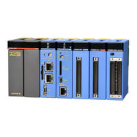
YOKOGAWA FA-M3V e-RT3 Plus Hardware Manual (274 pages)
Brand:
YOKOGAWA
| Category:
Controller
| Size: 3.77 MB
Table of Contents
Applicable Product
3
Precautions
4
Introduction
12
Copyrights and Trademarks
13
Table of Contents
15
Part a Standard Version
21
A1. System Configuration
23
System Configuration
23
Basic Configuration
23
Main Unit
23
Subunit
23
Slot Number
24
Example of Increasing the Number of I/O Points Using Fiber-Optic FA-Bus Type 2 Modules
25
A1.2 Restrictions on Module Installation
27
A1.2.2 Restrictions on CPU Module Installation
28
A1.2.3 Restrictions on I/O Module Installation
29
A1.2.4 Restrictions Due to Current Consumption
32
A1.3 Peripheral Tools Supporting the Program Development of the FA-M3
33
A2.1 Specifications
35
Common Specifications
35
Power Supply Specifications
36
A2.2 FA-M3 Controller Configuration
37
A2.2.1 Components
37
Module Names
37
FA-M3 Components
37
A2.3 Power Supply Modules
46
Power Supply Modules
46
F3PU30-0N/F3PU30-0S Power Supply Modules
49
Power Supply Modules
51
F3PU36-0N/F3PU36-0S Power Supply Module
53
A2.4 Base Modules
56
A2.5 I/O Modules
57
Components and Their Functions
57
External Dimensions
57
Isolation Methods
58
Terminal Arrangement
58
External Connection
58
F3XH04-3N High-Speed Input Module
59
Setting up the Pulse-Capture and Interrupt Functions
60
F3XA08-1N/F3XA08-2N AC Input Modules
64
F3XA16-1N AC Input Module
66
F3XC08-0N No-Voltage Contact Input Module
67
F3XC08-0C No-Voltage Contact Input Module (Independent Commons)
68
F3XD08-6F DC Input Module
69
F3XD16-3F/F3XD16-4F/F3XD16-3H DC Input Modules
70
F3XD32-3F/F3XD32-4F/F3XD32-5F DC Input Modules
72
F3XD64-3F/F3XD64-4F DC Input Modules
74
F3XD08-6N DC Input Module
76
F3XD16-3N/F3XD16-4N DC-Input Modules
78
F3XD32-3N/F3XD32-4N/F3XD32-5N DC Input Modules
80
F3XD64-3N/F3XD64-4N DC Input Modules
82
F3XD64-6M DC Input Module
84
F3YD04-7N Transistor Output Module
85
F3YA08-2N Triac Output Module
86
F3YC08-0C/F3YC08-0N Relay Output Module
88
F3YD08-6A/F3YD08-6B Transistor Output Modules
91
F3YD08-7A Transistor Output Module
93
F3YD14-5A/F3YD14-5B Transistor Output Modules
95
F3YC16-0N Relay Output Module
97
F3YD32-1A/F3YD32-1B Transistor Output Modules
99
F3YD32-1H Transistor Output Module (for High Speed Output)
101
F3YD32-1P/F3YD64-1P Transistor Output Modules (with Short-Circuit Protector)
103
F3YD32-1R/F3YD64-1R Transistor Output Modules (with Short-Circuit Protector)
105
F3YD32-1T TTL Output Module
109
F3YD64-1A Transistor Output Module
111
F3YD64-1F Transistor Output Module
113
F3YD64-1M Transistor Output Module
115
F3WD64-3P/F3WD64-4P Input/Output Modules (with Short-Circuit Protector)
117
F3WD64-3F/F3WD64-4F Input/Output Modules
121
F3WD64-3N/F3WD64-4N Input/Output Modules
125
ROM Packs
129
A2.7 Cables
131
Cables for Programming Tool
131
KM11-2N (for PC9801 (NEC))
131
KM11-2T/KM11-3T/KM11-4T (for DOS/V (IBM PC/AT Compatibles))
132
KM13-1S (USB-Serial Converter)
132
CPU Port/D-Sub 9-Pin Adapter Cable
133
Km10-0C
133
Cables for Connector Terminal Blocks
134
Km55-005, Km55-010, Km55-015, Km55-020, Km55-025, Km55-030
134
Fiber-Optic Cord
135
Km60
135
Fiber-Optic Cables
136
Km61, Km62, Km67, Km69
136
Km65
136
Monitor Cables (for F3SP08-2X, -3X, and -5X)
139
KM21-2A (D-Sub 25-Pin)
139
KM21-2B (D-Sub 9-Pin)
139
Monitor Cables (for F3SP66-4S and F3SP67-6S)
140
KM21-2T (D-Sub 9-Pin)
140
KM21-2N (D-Sub 25-Pin)
140
SIO Port/D-Sub 9-Pin Adaptor Cable (for F3SP66-4S and F3SP67-6S)
141
Km10-0S
141
A2.8 Terminal Block Unit and Connector Terminal Block
142
Ta40-0N
142
Ta50-0N/Ta50-1N/Ta50-2N
145
Ta60-0N
148
A2.9 Module Current Consumption Tables
150
A2.10 External Power Supply
154
A2.11 External Dimensions
155
A3. Installation and Wiring
161
A3.1 Environmental Conditions for Installation Within a Panel Enclosure
161
A3.2 Methods for Mounting the FA-M3 Within a Panel Enclosure
163
A3.2.1 Mounting Positions
163
A3.2.2 Mounting Dimensions
164
A3.2.3 Mounting on and Removing from a DIN Rail
165
A3.2.4 Attaching/Detaching the Module
168
A3.2.5 Mounting Depth and Space
170
System Design Considerations
172
A3.3.1 Power Line Wiring and Emergency-Stop Circuit
172
A3.3.2 Grounding Lines
173
A3.3.3 Relay Circuits
174
A3.3.4 Protection against Output Short-Circuit
174
A3.3.5 Interlocking
175
A3.3.6 Measures against Power Failure
176
A3.4 Noise Control Considerations
180
Wiring the Power Supply Module
182
A3.5.1 Re-Checking Specifications
182
A3.5.2 Wiring Materials
182
A3.5.3 Power Supply Wiring
183
A3.5.4 Grounding Procedure
185
Wiring I/O Modules
186
A3.6.1 Re-Checking Specifications
186
A3.6.2 Wiring Materials
186
A3.6.3 Terminal Blocks and Connectors
187
A3.6.4 Connecting Input Devices
189
A3.6.5 Connecting Output Devices
192
A3.7 External Cable Routing Requirements
194
A3.8 Calculating Power Consumption
195
CE Marking Conformance
196
A3.9.1 EMC Directive
197
A3.9.2 Low Voltage Directive
205
A4. Test Runs and Troubleshooting
209
A4.1 Test Run Procedure
209
A4.2 Test Run Precautions
210
Self-Diagnostic Functions
211
A4.3.1 CPU Module Operation at Power-On
211
A4.3.2 Fault Identification
213
A4.3.3
214
A4.4 Troubleshooting Procedure
217
A4.5 CPU Module Reset and Memory Clearance
218
A5. Maintenance and Inspection
221
A5.1 Replacing Modules
221
A5.2 Routine Inspection
222
Appendix A1 System-Wide Restrictions on
223
Module Installation
223
Appendix A1.1 Checking Compliance with Restrictions on
223
Appendix A1.2 Restrictions Due to the Number of Slots
227
Appendix A1.3 Restrictions Due to the Size of Data Area
228
Appendix A1.4 Restrictions Due to the Type of CPU Module
230
Appendix A1.4.1 for Sequence CPU Module Type
230
Appendix A1.4.2 for BASIC CPU Module Type
231
General
233
User's Manuals and Approved / Compliant Modules
233
Part B FA-M3 Value (F3SC21-1N)
241
B1. System Configuration
243
B1.1 System Configuration
243
B1.2 Restrictions on Module Installation
245
B1.2.1 Restrictions on Module Location
245
Restrictions Due to Current Consumption
245
B1.3 Peripheral Tools Supporting the Program Development of FA-M3
246
B2.1 Specifications
247
B2.2 System Configuration
248
B2.2.1 Components
248
B2.3 Sequence CPU Module
249
B2.3.1 Overview
249
B2.3.2 Power Supply Block of F3SP05-0P Module
249
B2.3.3 External Dimensions
251
Part C FA-M3 Value II (F3SC22-□□, F3SC23-□□)
253
C1.1 System Configuration
255
C1.2 Restrictions on Module Installation
257
C1.2.1 Restrictions on Module Location
257
Restrictions Due to Current Consumption
257
C1.3 Peripheral Tools Supporting the Program Development of FA-M3
258
C2.1 Specifications
259
C2.2 System Configuration
260
C2.2.1 Components
260
C2.3 Sequence CPU Module
261
C2.3.1 Overview
261
Power Supply Block of F3SP08-0P and F3SP08-SP Module C2-3
261
C2.3.3 External Dimensions
263
C2.4 F3WD32-3F Input/Output Module
264
Index
269
Revision Information
271
Advertisement
Advertisement
Related Products
YOKOGAWA FX103
YOKOGAWA FX106
YOKOGAWA FX112
YOKOGAWA Revolution FA-M3 R
YOKOGAWA STARDOM FCN-500
YOKOGAWA Vitesse FA-M3V
YOKOGAWA FA-M3 FA Link H Module
YOKOGAWA FA-M3 Fiber-optic FA Link H Module
YOKOGAWA FA-M3 F3LH01-1N
YOKOGAWA FA-M3 F3LH02-1N
YOKOGAWA Categories
Measuring Instruments
Test Equipment
Transmitter
Controller
Media Converter
More YOKOGAWA Manuals
Login
Sign In
OR
Sign in with Facebook
Sign in with Google
Upload manual
Upload from disk
Upload from URL