Sign In
Upload
Manuals
Brands
Xsens Manuals
Control Unit
MTi-1T
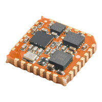
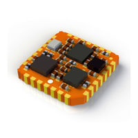
User Manuals: Xsens MTi-1T Inertial Measurement Unit
Manuals and User Guides for Xsens MTi-1T Inertial Measurement Unit. We have
3
Xsens MTi-1T Inertial Measurement Unit manuals available for free PDF download: User Manual, Integration Manual
Xsens MTi-1T User Manual (61 pages)
Brand:
Xsens
| Category:
GPS
| Size: 3 MB
Table of Contents
Table of Contents
3
References
8
Xsens Help Center and User Community
9
Introduction
10
Mti 10-Series
10
Mti-30 AHRS
10
Figure 1: Mti 10-Series
10
Mti-20 VRU
11
Mti-10 IMU
11
Mti 100-Series
11
Mti-G-710 GNSS/INS
11
Mti-300 AHRS
11
Figure 2: Mti 100-Series
11
Mti-200 VRU
12
Mti-100 IMU
12
Identifying Device Functionality Using the Unique Device Identifier
13
Table 1: Device ID's for 5Th Generation Mti
13
Product Code
14
Figure 3: Product Codes of Mti Devices
14
Figure 4: Example of a Label Showing the SN (Deviceid) and the Product Code
14
Evolution of Mti Products
15
Overview Mti Development Kit
15
Contents
15
Table 2: Evolution of Mti Products
15
Figure 5: Mti Development Kit
15
Installation
16
Transient Accelerations
16
Vibrations
17
Magnetic Materials and Magnets
17
Typical User Scenarios
18
MT Software Suite
18
Figure 6: Structure of the MT Software Suite
18
Using the Software Development Kit (SDK)
19
Direct Low-Level Communication with Mti
21
Figure 7: Functionality Implementation for Specific Products
21
Terms of Use of MT Software Suite
22
Table 3: Guidelines for the Use of the MT Software Suite
22
Mti System Overview
23
Calibration
23
Xsens Kalman Filter for VRU and AHRS Product Types
23
Using the Acceleration of Gravity to Stabilize Inclination (Roll/Pitch)
23
Using the Earth Magnetic Field to Stabilize Yaw
24
Estimating Gyro Bias in Magnetic Disturbed Environments
24
Initialization
24
Xkf3I Filter Profiles
25
Table 4: Filter Profiles for the Mti-200/Mti-300
25
Xsens Sensor Fusion Algorithm for Mti-G-710
26
Transient Accelerations
26
Magnetic Disturbances
26
Loss of GNSS
26
Mti-G-710 Filter Profiles
27
Table 5: Filter Profiles for the Mti-G-710 GNSS/INS
27
GNSS Platform
28
Orientation Smoother
28
Active Heading Stabilization (AHS)
28
In-Run Compass Calibration (ICC)
29
Best Practices for Xsens Sensor Fusion Performance at Start-Up
29
Manual Gyro Bias Estimation
30
Apply 3D Motion
30
Output Specification
31
Overview of Data Outputs
31
Mtdata2 Output in Xbus Protocol
31
ASCII Output (NMEA)
31
Coordinate Systems
31
Calibrated Inertial Data and Magnetic Field Data
31
Delta_Angle and Delta_Velocity
32
Orientation Data
32
Figure 8: Coordinate System of the Encased Mti (Note: Origin Is Located at the Accelerometers)
32
Figure 9: Coordinate System of the Mti-OEM (Note: Origin Is Located at the Accelerometers)
32
Velocity Data
34
Position Data
34
Table 6: Yaw in Different Coordinate Systems
34
Orientation Performance Specification
35
Table 7: Orientation Performance Specification
35
Position and Velocity Performance Specification (Mti-G-710)
36
Sensor Data Performance Specification
36
Table 8: Position and Velocity Performance Specifications (Mti-G-710)
36
Gyroscopes
37
Accelerometers and Magnetometer
37
Table 9: Gyroscope Specifications
37
Table 10: Accelerometers and Magnetometers Specification
37
Table 11: Magnetometer Specifications
37
Barometer
38
GPS/GNSS Receiver
38
Table 12: Barometer Specification
38
Table 13: GNSS Receiver Specification
38
Built-In Self-Test
39
Test and Calibration Parameters
39
Sensors Data Outputs
40
Physical Sensor Model
40
Calibrated Delta_Q and Delta_V Outputs
41
Calibrated Inertial and Magnetic Data Outputs
41
High-Rate (HR) Inertial Data Outputs
41
Table 14: Output Specifications ∆Q and ∆V Outputs
41
Table 15: Output Specifications Inertial and Magnetometer Data Outputs
41
Table 16: Output Specifications High-Rate Calibrated Inertial Data Outputs
41
Free Acceleration
42
Uncalibrated Raw Output Mode
42
Reset of Reference Co-Ordinate Systems
42
Timestamp and Packet Counter Output
42
Status Byte
42
Table 17: Output Specifications Sensor Component Readout (SCR)
42
Communication
43
Communication Timing
43
Triggering and Synchronization
43
Internal Clock Accuracy
43
Clock of Mti's Without GNSS Receiver
43
Clock of Mti-G-710
43
Serial Connection Settings
44
Serial or USB Communication
44
Transceiver Voltage Levels
44
Table 18: Transceiver Voltage Levels
44
Physical Specifications
45
Physical Properties Overview
45
Power Supply
45
Power Consumption Specification
45
Table 19: Physical Properties Overview
45
Table 20: Power Consumption Depending on Communication Interface
45
Alternative 3V3 Power Supply
46
Mechanical and Electrical Interface Specifications
46
Encased Mti Connectors Overview
46
Table 21: Pin Configuration CA-USB-Mti
47
Figure 10: Drawing of CA-USB-Mti
47
Figure 11: Drawing of CA-MP2-Mti
47
OEM Connections Overview
48
Table 22: Pin Configuration Table CA-MP2-Mti
48
Table 23: Part Numbers Headers on Mti OEM
48
Table 24: Pin Connections OEM Headers
49
Figure 12: the Pins of the Headers on the Mti-OEM Are Clearly Marked
49
Additional Interface Specifications
50
Table 25: Part Numbers for Sockets that Fit the Headers on the Mti OEM
50
Figure 13: Standard Ribbon Cables Can be Used for Connecting the Mti OEM to Another
50
Cable Specifications
51
Using the Mti Mk5 with an External USB Converter
51
Table 26: Interface Specifications of the Synchronization Lines
51
Figure 14: Internals of a CA-USB#-MTI Converter Box
51
Housing Mechanical Specifications
52
Environmental Protection of the Housing
52
Table 27: Pin Connections for JP101/JP102 in the USB Converter Box
52
Table 28: Pin Connections for JP103 in the USB Converter Box
52
Dimensions Mti
53
Mounting the Mti-OEM
53
Figure 15: Using a Heat Shrink Tube to Position the Mounting Screws
53
Mti 10-Series Technical Drawing
54
Figure 16: Mti 10-Series Technical Drawing
54
Mti 100-200-300 Technical Drawing
55
Figure 17: Mti 100-Series Technical Drawing
55
Mti-G-700/710 Technical Drawing
56
Figure 18: Mti-G-710 Technical Drawing
56
Mti OEM Technical Drawing
57
Figure 19: Mti OEM Technical Drawing
57
Important Notices
58
Safety Instructions
58
Absolute Maximum Ratings
58
Maintenance
58
EU Declaration of Conformity
59
FCC Declaration of Conformity
60
Warranty and Liability
61
Customer Support
61
Advertisement
Xsens MTi-1T User Manual (101 pages)
Brand:
Xsens
| Category:
Computer Hardware
| Size: 5 MB
Table of Contents
Table of Contents
3
Mti 1-Series
4
Datasheet
5
General Information
6
Sensor Specifications
13
Functional Description
15
Mti 1-Series Architecture
33
System and Electrical Specifications
44
Design and Packaging
48
Declaration of Conformity
53
DK User Manual
56
General Information
57
Introduction
60
Getting Started
63
Shield Board
68
Integration Manual
81
General Information
82
Power Supply
84
Interfaces
86
Design
93
Packaging
100
Handling
100
Xsens MTi-1T Integration Manual (23 pages)
MTi-1 series
Brand:
Xsens
| Category:
Control Unit
| Size: 2 MB
Table of Contents
Table of Contents
3
1 General Information
5
Table 1: Mti 1-Series Latest Generation
5
Table 2: Mti 1-Series Previous Generation
5
2 Power Supply
6
Main Supply Voltage (Vddio)
6
Analog Supply Voltage (Vdda)
6
Single Power Supply Configuration
6
Figure 1: External Components Single Supply (I C Interface)
6
Power Supply Specifications
7
Table 3: Maximum Operating Voltage Ratings
7
3 Interfaces
8
Pin Configuration
8
Communication to Host
8
Figure 2: Pin Configuration of the Mti 1-Series Module (Top View)
8
Table 4: Host Communication Interfaces Specifications
8
PSEL Serial Host Communication Interface Selection
9
Table 5: Serial Host Interface Selection
9
Figure 3: External Components
10
I 2 C
10
Table 6: List of I 2 C Addresses
10
Figure 4: Connections (SPI Interface)
11
Figure 5: Connections (UART Interface Full-Duplex)
11
Spi
11
Uart
11
Gnss Receiver and Barometer Interface
12
Table 7: GNSS Receiver Interface Specifications
12
Figure 6: Connections (GNSS Interface)
12
I/Opins
13
Reset
13
Sync_In
13
Dnc/Reserved Pins
13
Table 8: I/O Interface Specifications
13
4 Design
14
Pcb Layout
14
Frames of Reference Used in Mti 1-Series
14
Figure 7: Layout Example
14
Figure 8: Default Sensor Fixed Coordinate System for the Mti 1-Series Module
14
Origin of Measurements
15
Mechanical Stress
15
Pushbutton Contacts
15
Figure 9: Location Origin of Measurements
15
Anchor Points
16
Figure 10: High Mechanical Stress in Diagonal Crossover between Anchor Points
16
Figure 11: Reducing Anchor Points to Reduce Overall Stress in the PCB
16
Figure 12: Keeping the Mti 1-Series Module Away from High Mechanical Stress Areas
16
Vibrations
17
Heat
17
Sockets
17
Magnetometer
17
Ferromagnetic Materials
17
High Currents
17
Footprint
18
Figure 13: Recommended Mti 1-Series Module Footprint
18
5 Packaging
19
Tray Packaging Information
19
Reel Packaging Information
20
Package Drawing
21
Table 9: Mti 1-Series Module Generations
21
Figure 14: Mti 1-Series V1.1 Dimensions and Sensor Locations
21
Figure 15: Mti 1-Series V2.0 Dimensions and Sensor Locations
21
Figure 16: Location PCB Number on Mti 1-Series Module (Bottom View)
21
6 Handling
22
Reflow Specification
22
Ultrasonic Processes
22
Figure 17: Reflow Classification Profile (Not to Scale)
22
Electrostatic Discharge (Esd)
23
Advertisement
Advertisement
Related Products
Xsens MTi 1 Series
Xsens MTi-1-8A7G6
Xsens MTi-1R
Xsens MTi-1-8A7G6T
Xsens MTi-1-8A7G6R
Xsens MTi-3
Xsens MTI-2T
Xsens MTI-3T
Xsens MTI-7R
Xsens MTi-2-8A7G6
Xsens Categories
Measuring Instruments
Microcontrollers
GPS
Accessories
Analytical Instruments
More Xsens Manuals
Login
Sign In
OR
Sign in with Facebook
Sign in with Google
Upload manual
Upload from disk
Upload from URL