Sign In
Upload
Manuals
Brands
Xantrex Manuals
Inverter
GT100-208
Xantrex GT100-208 Manuals
Manuals and User Guides for Xantrex GT100-208. We have
1
Xantrex GT100-208 manual available for free PDF download: Operation And Maintenance Manual
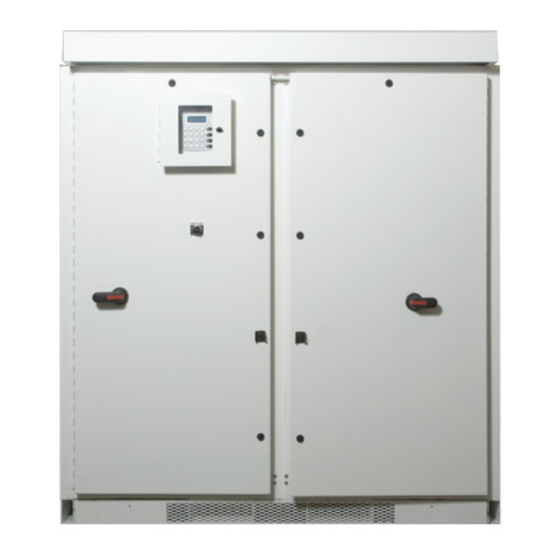
Xantrex GT100-208 Operation And Maintenance Manual (118 pages)
GT100 Series Grid-Tied Photovoltaic Inverter
Brand:
Xantrex
| Category:
Inverter
| Size: 6.13 MB
Table of Contents
About this Manual
5
Conventions Used
6
Important Safety Instructions
9
General Safety Precautions
11
Personal Safety
11
Wiring Requirements
12
Intended Use
16
Interconnection Standards Compliance
16
Table of Contents
17
1 Introduction
25
Description of the GT100
26
Power Conversion System
26
Advanced Design Features
26
Physical Characteristics
27
Figure 1-1 Main Inverter (Open Enclosure View)
27
Figure 1-2 GT100 Major Sections
28
AC Interface
29
AC Utility Terminals
29
Figure 1-3 AC Utility Terminals
29
Auxiliary Control Interface
30
Communications Circuit
30
Figure 1-4 Auxiliary Control Terminals
30
Power Electronics
31
Converter Control Unit (CCU2)
31
Power Electronics Matrix
31
DC Interface
32
DC Terminals
32
Figure 1-5 DC Terminals
32
Table 1-1 DC Terminal Polarity
32
Fused Combiner (Optional)
33
Figure 1-6 GT Fused Combiner Connectors
33
Circuit Diagram
34
Figure 1-7 GT100 Circuit Diagram
34
Operator Interface Controls
35
Figure 1-8 GT100 Operator Interface Components
35
Auxiliary Enable/Disable
36
Emergency Stop (E-STOP)
36
Figure 1-9 On/Off Switch
36
On/Off Switch
36
AC Disconnect and DC Disconnect Switches
37
Figure 1-10 AC and DC Disconnect Switches
37
Operation Features
38
Fixed Unity Power Factor Operation
38
Peak Power Tracking
38
Utility Voltage/Frequency Fault Automatic Reset
39
Figure 1-11 Maximum Peak Power Tracking
39
Safety Features
40
Anti-Island Protection
40
PV Ground Fault Detection
40
DC Over-Voltage Detection
40
Communication Features and Methods
41
System Status and Fault Reporting
41
Figure 1-12 VFD Display and UFCU Location
42
Data Logging
43
Oscillography
44
Optional Equipment
45
Communication Modems
45
PV Combiner
45
2 Operation
47
Description of System Operation
48
Overview
48
Faults
48
Operating States
49
Figure 2-1 State Transition Diagram
49
Automatic Sleep Test
50
Manual Current
50
Power Tracking
50
Shutdown
50
Transition
50
Fault
51
Matrix Test
51
Figure 2-2 Operating States Flow Chart for Power Tracking
52
Operator Interface
53
UFCU Keypad Operation and VFD Display
53
Figure 2-3 the Universal Front Panel Control Unit (UFCU) and VFD
53
VFD Display - Initialization Screen
54
Standard Display
55
Menu Structure
55
Read Menu
56
Figure 2-5 Operator Interface Menu Diagram
56
Table 2-1 Scrolling through the Read Menu Parameters
57
Figure 2-6 Scrolling through the Read Menu
58
Table 2-2 Read Menu Descriptions
59
Figure 2-7 Read-By-ID Feature
61
WRITE Menu
62
Table 2-3 Write Menu Parameters
63
Commanding Goal State Changes
68
Figure 2-8 State Transition Diagram
68
Setting the Date and Time
69
Manual State Transitions
70
Automatic State Transitions
70
Auto-Restart Feature
71
Figure 2-9 VFD Showing Fault Code
71
Energize Procedure (Startup)
72
Lockout and Tag
72
Figure 2-10 AC Utility Terminals
73
Computer Communications with the GT100
74
Figure 2-11 DC Terminals
74
3 Commissioning
75
Commissioning Procedure
76
Starting the Commissioning Test
77
Serial Number
77
Inverter Enclosure
77
Verify AC Voltage
77
Verify DC Voltage
77
Apply Grid Voltage
78
Front Panel Display
78
Confirm AC Operational Parameters
78
Confirm DC Operational Parameters
78
Confirm Power Tracker Configuration Operational Parameters
79
Apply DC Voltage
79
Matrix Test
79
Operate Inverter
79
Completed Commissioning
80
4 Troubleshooting
81
Faults and Fault Codes
82
General Troubleshooting
83
Clearing Faults Manually
84
Figure 4-1 VFD Showing Fault Code
84
Fault Code Descriptions
85
Table 4-1 Fault Codes
85
5 Preventative Maintenance
95
Maintenance Safety
96
Operational Safety Procedures
96
Lockout and Tag (De-Energize/Isolation Procedure)
96
Figure 5-1 AC Terminal Connections from the Utility
97
Figure 5-2 DC Terminal Locations
98
Figure 5-3 DC Terminal Locations (with GTFC Installed)
98
Maintenance Intervals
99
Periodic Maintenance
99
Monthly Intervals or as Required
99
Six Month Intervals
99
A Specifications
101
System Specifications
102
Environmental Specifications
102
Table A-1 Environmental Specifications
102
Electrical Specifications
103
Regulatory Specifications
103
Table A-2 Electrical Specifications
103
Table A-3 Regulatory Specifications
103
Over Voltage, under Voltage and Frequency Ranges
104
Table A-4 Over/Under Voltage and Over/Under Frequency Ranges
104
Bolt Sizing and Torque Requirements
105
Table A-5 AC Terminal Bolt Size and Torque Values
105
Table A-6 DC Terminal Bolt Size and Torque Values
105
Table A-7 DC Terminal Conductor Range and Torque Values
105
Dimensions
106
Figure A-1 GT100 Dimensions
106
Table A-8 Auxiliary Control Interface Screw Size and Torque Values
106
B Commissioning Test Record
107
Warranty and Return Information
111
Return Material Authorization Policy
113
Return Procedure
113
Out of Warranty Service
113
Warranty Registration
114
Index
115
Advertisement
Advertisement
Related Products
Xantrex GT100E
Xantrex GT100-480
Xantrex GT100E MS
Xantrex GT100-208-NG
Xantrex GT100-208-PG
Xantrex GT100-480-NG
Xantrex GT100-480-PG
Xantrex GT100 Series
Xantrex GT2.8-AU-QC-230
Xantrex GT 3.8-SP
Xantrex Categories
Inverter
Power Supply
Battery Charger
Power Pack
Controller
More Xantrex Manuals
Login
Sign In
OR
Sign in with Facebook
Sign in with Google
Upload manual
Upload from disk
Upload from URL