Sign In
Upload
Manuals
Brands
Woodward Manuals
Controller
DTSC-200
Woodward DTSC-200 Transfer Switch Manuals
Manuals and User Guides for Woodward DTSC-200 Transfer Switch. We have
6
Woodward DTSC-200 Transfer Switch manuals available for free PDF download: Configuration Manual, Manual, Installation Manual, Operation Manual
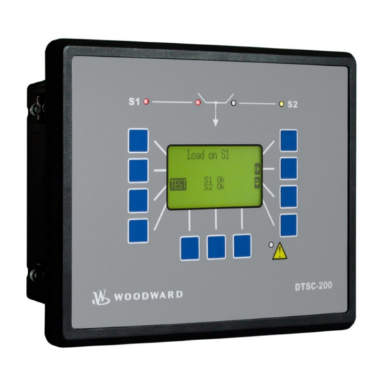
Woodward DTSC-200 Configuration Manual (158 pages)
ATS Controller
Brand:
Woodward
| Category:
Controller
| Size: 6.01 MB
Table of Contents
Table of Contents
3
Chapter 1. General Information
8
Table 1-1: Manual - Overview
8
• the List of Parameters (Appendix B) Is Updated. for Details See Page 143 Ff.
8
Chapter 2. Configuration
9
Configuration Via the Front Panel
9
Configuration Via PC
10
Install Toolkit Configuration and Visualization Software
10
Install Toolkit Software
10
Install Toolkit Configuration Files
11
Starting Toolkit Software
12
Configure Toolkit Software
13
Connect Toolkit and the DTSC-200 Unit
14
View DTSC-200 Data with Toolkit
16
Figure 2-1: Toolkit - Visualization Screen
16
Figure 2-2: Toolkit - Analog Value Trending Screen
16
Configure the DTSC-200 with Toolkit
17
Figure 2-3: Toolkit - Configuration Screen
17
General Information
18
Important Designations
18
Signal and Command Abbreviations
18
Monitoring Functions
19
Function of the Inputs and Outputs
20
Chapter 3. Parameters
22
Language
23
Password
23
Event History
24
Figure 3-1: Event History- Display
24
Measuring
25
Measuring: Rated Values
25
Measuring: Transformers
29
Application
31
Application: Application Mode
31
Application: Transfer Timers
32
Figure 3-2: Source Stable and Outage Timers
37
Application: Transfer Logics (Logicsmanager)
38
Figure 3-3: External Timer Bypass - Push Button
40
Application: Elevator Pre-Signal
42
Figure 3-4: Elevator Pre-Signal - Example 1
43
Figure 3-5: Elevator Pre-Signal - Example 2
43
Figure 3-6: Elevator Pre-Signal - Example 3
43
Application: Motor Load Disconnect
44
Application: Source Priority Selection
45
Figure 3-7: Source Priority Selection - S1 Preferred
46
Figure 3-8: Source Priority Selection - S2 Preferred
46
Table 3-1: Application - Load Shed with Standard Transition Switch
49
Figure 3-9: Load Shed Relay Wiring - Standard Transition Switch
50
Figure 3-10: Load Shed Relay Wiring - Delayed or Closed Transition Switch
50
Table 3-2: Application - Load Shed with Delayed or Closed Transition Switch
50
Breaker
52
Breaker: Transfer Switch Type
52
Figure 3-11: Open Transition Switch - Connected to Source 1
52
Figure 3-12: Open Transition Switch - Connected to Source 2
52
Figure 3-13: Delayed Transition Switch - Connected to Source 1
53
Figure 3-14: Delayed Transition Switch - Neutral Position
53
Figure 3-15: Delayed Transition Switch - Connected to Source 2
53
Figure 3-16: Closed Transition Switch - Connected to Source 1
54
Figure 3-17: Closed Transition Switch - Neutral Position
54
Figure 3-18: Closed Transition Switch - Connected to Source 1 and 2 (Overlap Position)
54
Figure 3-19: Closed Transition Switch - Connected to Source 2
54
Figure 3-20: Breaker - Transition Pulse
58
Test Modes
61
Timer Exerciser
62
Figure 3-21: Test Modes - Load Test Configured for Timer Exerciser
62
Figure 3-22: Test Modes - No-Load Test Configured for Timer Exerciser
62
Figure 3-23: Test Modes - Parameter Ids of the Timer Exercisers
63
Figure 3-24: Test Modes - Configuring Exerciser 1 for a Daily Exercise
64
Figure 3-25: Test Modes - Configuring Exerciser 2 for a Weekly Exercise
64
Figure 3-26: Test Modes - Configuring Exerciser 3 for a 14-Day Exercise
64
Figure 3-27: Test Modes - Configuring Exerciser 4 for a One Event Exercise
65
Figure 3-28: Test Modes - Display Screen with Pending Exercise Event
65
Figure 3-29: Test Modes - Display Screen with Running Load Test
65
Monitoring
66
Monitoring: Alarm Acknowledgement
66
Monitoring: Limit Switch Monitoring
66
Monitoring: Source 1 Monitoring
67
Monitoring: Source 2 Monitoring
72
Monitoring: In-Phase Monitoring (Synch Check)
77
Figure 3-30: Inphase Monitoring
77
Figure 3-31: Switch Reaction Time
82
Monitoring: Overcurrent
86
Figure 3-32: Monitoring - Load Time-Overcurrent
86
Table 3-3: Monitoring - Standard Values - Load Time-Overcurrent
86
Monitoring: Overload
88
Figure 3-33: Monitoring - Overload
88
Table 3-4: Monitoring - Standard Values - Overload
88
Monitoring: Engine, Start Failure Source 1
90
Monitoring: Engine, Start Failure Source 2
90
Monitoring: Battery, Overvoltage
91
Figure 3-34: Monitoring - Battery Overvoltage
91
Table 3-5: Monitoring - Standard Values - Battery Overvoltage
91
Monitoring: Battery, Undervoltage
93
Figure 3-35: Monitoring - Battery Undervoltage
93
Table 3-6: Monitoring - Standard Values - Battery Undervoltage
93
Monitoring: Canopen Interface
95
Discrete Inputs
96
Figure 3-36: Discrete Inputs - Control Inputs - Operation Logic
96
Table 3-7: Discrete Inputs - Assignment
96
Table 3-8: Discrete Inputs - Parameter Ids
97
Table 3-9: External Discrete Inputs - Parameter Ids
97
Discrete Outputs (Logicsmanager)
98
Table 3-10: Relay Outputs - Assignment
98
Table 3-11: Discrete Outputs - Parameter Ids
99
Table 3-12: External Discrete Outputs - Parameter Ids
99
Counters
100
Configure Counters: Operation Hours, Kwh, and Kvarh
100
Logicsmanager
102
Logicsmanager: Internal Flags
102
Table 3-13: Internal Flags - Parameter Ids
102
Logicsmanager: Timer
103
Interfaces
105
Interfaces: CAN Bus (Flexcan)
105
Figure 3-37: Interfaces - Principle of PDO Mapping
108
Interfaces: Serial Interface 1 (RS-232)
113
Interfaces: Serial Interface 2 (RS-485)
113
System
114
System: Configure Display Backlight
114
System: Configure Daylight Saving Time
115
Table 3-14: Daylight Saving Time - Configuration Example
115
Table 3-15: Daylight Saving Time - Examplary Dates
115
System: Password System
117
System: Real-Time Clock Set
119
System: Versions
120
Figure 3-38: Logicsmanager - Function Overview
122
Table 3-16: Logicsmanager - Command Overview
122
Figure 3-39: Logicsmanager - Display in Toolkit
123
Figure 3-40: Logicsmanager - Display in LCD
123
Logical Symbols
123
Table 3-17: Logicsmanager - Logical Symbols
123
Logical Outputs
124
Logical Outputs: Internal Flags
124
Logical Outputs: Internal Functions
124
Logical Outputs: Relay Outputs
125
Logical Command Variables
126
Logical Command Variables: [00.00] - Internal Flags
126
Logical Command Variables: [01.00] - Alarm Classes
127
Logical Command Variables: [03.00] - Engine Control
127
Logical Command Variables: [04.00] - Operating Status
128
Logical Command Variables: [06.00] - Load Alarms
128
Logical Command Variables: [08.00] - System Alarms
129
Logical Command Variables: [09.00] - Discrete Inputs
129
Logical Command Variables: [11.00] - Time Functions
130
Logical Command Variables: [12.00] - External Discrete Inputs (Expansion Board)
130
Logical Command Variables: [13.00] - Internal Relay Output Status
131
Logical Command Variables: [14.00] - External Relay Outputs Status
131
Logical Command Variables: [19.00] - ATS Status Flags
132
Logical Command Variables: [20.00] - ATS Status Flags
132
Logical Command Variables: [21.00] - ATS Alarms
133
Logical Command Variables: [98.00] - Logicsmanager Outputs
133
Factory Setting
134
Factory Setting: Functions
134
Factory Setting: Relay Outputs
139
Factory Setting: Internal Flags
141
Discrete Inputs
142
Product Service Options
153
Returning Equipment for Repair
153
Packing a Control
154
Return Authorization Number RAN
154
Replacement Parts
154
How to Contact Woodward
155
Engineering Services
156
Technical Assistance
157
Advertisement
Woodward DTSC-200 Manual (141 pages)
ATS Controller
Brand:
Woodward
| Category:
Controller
| Size: 3.62 MB
Table of Contents
Table of Contents
3
Chapter 1. General Information
8
Table 1-1: Manual - Overview
8
Chapter 2. Configuration
9
Configuration Via the Front Panel
9
Configuration Using the PC
10
General Information
11
Important Designations
11
Signal and Command Abbreviations
11
Monitoring Functions
12
Function of the Inputs and Outputs
13
Chapter 3. Parameters
15
Language
16
Password
16
Event History
17
Figure 3-1: Event History- Display
17
Measuring
18
Measuring: Rated Values
18
Measuring: Transformers
22
Application
24
Application: Application Mode
24
Application: Transfer Timers
25
Figure 3-2: Source Stable and Outage Timers
28
Application: Transfer Logics (Logicsmanager)
29
Figure 3-3: External Timer Bypass - Push Button
31
Application: Elevator Pre-Signal
33
Figure 3-4: Elevator Pre-Signal - Example 1
34
Figure 3-5: Elevator Pre-Signal - Example 2
34
Figure 3-6: Elevator Pre-Signal - Example 3
34
Application: Motor Load Disconnect
35
Application: Source Priority Selection
36
Figure 3-7: Source Priority Selection - S1 Preferred
37
Figure 3-8: Source Priority Selection - S2 Preferred
37
Table 3-1: Application - Load Shed with Standard Transition Switch
40
Figure 3-9: Load Shed Relay Wiring - Standard Transition Switch
41
Figure 3-10: Load Shed Relay Wiring - Delayed or Closed Transition Switch
41
Table 3-2: Application - Load Shed with Delayed or Closed Transition Switch
41
Breaker
42
Breaker: Transfer Switch Type
42
Figure 3-11: Open Transition Switch - Connected to Source 1
42
Figure 3-12: Open Transition Switch - Connected to Source 2
42
Figure 3-13: Delayed Transition Switch - Connected to Source 1
43
Figure 3-14: Delayed Transition Switch - Neutral Position
43
Figure 3-15: Delayed Transition Switch - Connected to Source 2
43
Figure 3-16: Closed Transition Switch - Connected to Source 1
44
Figure 3-17: Closed Transition Switch - Neutral Position
44
Figure 3-18: Closed Transition Switch - Connected to Source 1 and 2 (Overlap Position)
44
Figure 3-19: Closed Transition Switch - Connected to Source 2
44
Figure 3-20: Breaker - Transition Pulse
47
Test Modes
50
Monitoring
51
Monitoring: Alarm Acknowledgement
51
Monitoring: Limit Switch Monitoring
51
Monitoring: Source 1 Monitoring
52
Monitoring: Source 2 Monitoring
57
Monitoring: In-Phase Monitoring (Synch Check)
62
Figure 3-21: Inphase Monitoring
62
Figure 3-22: Switch Reaction Time
65
Table 3-3: Calculation of the Phase Angle Deviation
66
Monitoring: Overcurrent
68
Figure 3-23: Monitoring - Load Time-Overcurrent
68
Table 3-4: Monitoring - Standard Values - Load Time-Overcurrent
68
Monitoring: Overload
70
Figure 3-24: Monitoring - Overload
70
Table 3-5: Monitoring - Standard Values - Overload
70
Monitoring: Engine, Start Failure Source 1
72
Monitoring: Engine, Start Failure Source 2
72
Monitoring: Battery, Overvoltage
73
Figure 3-25: Monitoring - Battery Overvoltage
73
Table 3-6: Monitoring - Standard Values - Battery Overvoltage
73
Monitoring: Battery, Undervoltage
75
Figure 3-26: Monitoring - Battery Undervoltage
75
Table 3-7: Monitoring - Standard Values - Battery Undervoltage
75
Monitoring: Canopen Interface
77
Discrete Inputs
78
Figure 3-27: Discrete Inputs - Control Inputs - Operation Logic
78
Table 3-8: Discrete Inputs - Assignment
78
Table 3-9: Discrete Inputs - Parameter Ids
79
Table 3-10: External Discrete Inputs - Parameter Ids
79
Discrete Outputs (Logicsmanager)
80
Table 3-11: Relay Outputs - Assignment
80
Table 3-12: Discrete Outputs - Parameter Ids
81
Table 3-13: External Discrete Outputs - Parameter Ids
81
Counters
82
Configure Counters: Operation Hours, Kwh, and Kvarh
82
Logicsmanager
83
Logicsmanager: Internal Flags
83
Table 3-14: Internal Flags - Parameter Ids
83
Logicsmanager: Timer
84
Interfaces
86
Interfaces: CAN Bus (Flexcan)
86
Figure 3-28: Interfaces - Principle of PDO Mapping
89
Interfaces: Serial Interface 1 (RS-232)
94
Interfaces: Serial Interface 2 (RS-485)
94
System
95
System: Configure Display Backlight
95
System: Configure Daylight Saving Time
96
Table 3-15: Daylight Saving Time - Configuration Example
96
System: Password System
97
System: Real-Time Clock Set
99
System: Versions
100
Logicsmanager
101
Figure 3-29: Logicsmanager - Function Overview
102
Table 3-16: Logicsmanager - Command Overview
102
Logical Symbols
103
Figure 3-30: Logicsmanager - Display in Leopc
103
Figure 3-31: Logicsmanager - Display in LCD
103
Table 3-17: Logicsmanager - Logical Symbols
103
Logical Outputs
104
Logical Outputs: Internal Flags
104
Logical Outputs: Internal Functions
104
Logical Outputs: Relay Outputs
105
Logical Command Variables
106
Logical Command Variables: [00.00] - Internal Flags
106
Logical Command Variables: [01.00] - Alarm Classes
107
Logical Command Variables: [03.00] - Engine Control
107
Logical Command Variables: [04.00] - Operating Status
108
Logical Command Variables: [06.00] - Alarms of the Load
108
Logical Command Variables: [08.00] - Alarms of the System
109
Logical Command Variables: [09.00] - Discrete Inputs
109
Logical Command Variables: [11.00] - Time Functions
110
Logical Command Variables: [12.00] - External Discrete Inputs (Expansion Board)
110
Logical Command Variables: [13.00] - Status of the Internal Relay Outputs
111
Logical Command Variables: [14.00] - Status of the External Relay Outputs
111
Logical Command Variables: [19.00] - ATS Status Flags
112
Logical Command Variables: [20.00] - ATS Status Flags
112
Logical Command Variables: [21.00] - ATS Alarms
113
Logical Command Variables: [98.00] - Logicsmanager Outputs
113
Factory Setting
114
Factory Setting: Functions
114
Factory Setting: Relay Outputs
119
Factory Setting: Internal Flags
121
Discrete Inputs
122
Appendix B. Geteventlog
123
Geteventlog Software
123
Installing Geteventlog
123
Starting Geteventlog
123
Figure 3-32: Geteventlog - Interface Configuration
123
Figure 3-33: Geteventlog - Event Logger Content
124
Figure 3-34: Geteventlog - Event Logger Content in Excel
124
Resetting the Event Logger
125
Table 3-18: Event Logger - Event Texts and Numbers
125
Appendix C. List of Parameters
126
Appendix D. Service Options
136
Product Service Options
136
Returning Equipment for Repair
136
Packing a Control
137
Return Authorization Number RAN
137
Replacement Parts
137
How to Contact Woodward
138
Engineering Services
139
Technical Assistance
140
Woodward DTSC-200 Manual (86 pages)
ATS Controller
Brand:
Woodward
| Category:
Controller
| Size: 4.95 MB
Table of Contents
Table of Contents
3
Chapter 1. General Information
6
Related Documents
6
Table 1-1: Manual - Overview
6
Interface Overview
7
Figure 1-1: Interface Overview
7
Figure 1-2: Interface Overview - Serial Interface Modbus Full-Duplex
8
Figure 1-3: Interface Overview - Serial Interface Modbus Half-Duplex
8
Modbus Half/Full Duplex Application
8
CAN Bus
9
Figure 1-4: CAN Bus Topology
9
Figure 1-5: Interface - the CAN Bus Loop
9
Chapter 2. Data Telegrams
10
Interface Monitoring
10
Transmit Telegram
10
Modbus
10
Canopen
10
Receive Telegram
11
Modbus
11
Canopen
11
Chapter 3. Serial Interface
12
Overview
12
Figure3-1: Serial Interface - Overview
12
Modbus RTU Slave
13
General Information
13
Configuration
13
Modbus Addressing and Data Model
14
Visualization
15
Figure 3-2: Modbus - Visualization Configurations
15
Table 3-1: Modbus - Address Range Block Read
15
Configuration
16
Table 3-2: Modbus - Address Calculation
16
Table 3-3: Modbus - Data Types
16
Figure 3-3: Modbus - Configuration Example 1
17
Figure 3-4: Modbus - Configuration Example 2
17
Figure 3-5: Modbus - Configuration Example 3
18
Exception Responses
19
Table 3-4: Modbus - Exception Responses
19
Canopen
20
Introduction
20
C Hapter 4. Can Open
20
Server Data Objects (SDO) - Communication
21
Figure 4-1: Canopen Interface - Overview
22
Process Data Objects (PDO)
23
Setting the Transmit PDO (Examples)
24
Figure 4-2: Canopen Interface - Canopen Configuration Software
25
SYNC Message
25
Using a Canopen Configuration Program
25
Settings for Connection with External Devices
26
Figure 4-3: Canopen Interface - External Devices
26
Expansion with One IKD 1 (8 Additional External DI/DO)
27
Figure 4-4: Canopen Schnittstelle - Einstellungen für Externe Geräte
27
Expansion with Two IKD 1 (16 Additional External DI/DO)
28
Figure 4-5: Canopen Interface - Expansion with Two IKD 1
28
Expansion with the Phoenix Terminal IL CAN BK 16DI 16DO
30
Figure 4-6: Canopen Interface - Expansion with Phoenix Terminal
30
Description of the DTSC Parameters
32
Interfaces: General
32
General Canopen Parameters
33
Canopen Receive PDO (RPDO) {X} ({X} = 1/2)
35
Combine Functions with each Other
35
Canopen Transmit PDO (TPDO) {X} ({X} = 1 to 4)
36
FAQ CAN Bus
38
Recommendations of Woodward
38
Device Combinations and Bus Load
38
Transmission Telegram
41
Data Protocol 4701
41
Data Protocol 4800 (Source 1 Data)
50
Data Protocol 4801 (Source 2 Data)
52
Data Protocol 4802 (Source 1 Data)
55
Data Protocol 4803 (Source 2 Data)
57
Remote Control Telegram
60
Description of the Common Data Types
61
Structure of the PDO-COB-ID Entry (UNSIGNED32)
61
Description of the Object Parameter
62
Data Format of Different Functions
69
Receiving Messages
69
Definition of Protocol Descriptions
70
Unsigned Integer
70
Signed Integer
71
Transmission Telegram
72
Canopen: Mapping Parameter
74
Remote Control
79
Configuration of the Logicsmanager Functions
79
Figure 4-7: Display Screen - Ext. Acknowledge
79
Remote Control Telegram
80
Remote Control Via CAN
80
Remote Acknowledgement
80
Figure 4-8: Display Screen - Configure CAN Interface
80
Figure 4-9: Canopen Request Data for Node ID 1
81
Figure 4-10: Display Screen - Configure Device Number
81
Figure 4-11: Canopen Request Data for Node ID 2
81
Figure 4-12: Display Screen - Configure Server Sdos
82
Remote Control Via Modbus
83
Figure 4-13: Canopen Request Data for Additional Server SDO
83
Figure 4-14: Modbus - Remote Control Parameter 503
84
Figure 4-15: Modbus - Write Register
84
Sending a Data Protocol Via TPDO
85
Cyclically Sending of Data
85
Sending of Data on Request
85
Figure 4-16: Cyclical Sending of Data - Sync Message Request
85
Figure 4-17: Cyclical Sending of Data - Reply
85
Advertisement
Woodward DTSC-200 Installation Manual (41 pages)
ATS Controller
Brand:
Woodward
| Category:
Controller
| Size: 2.34 MB
Table of Contents
Table of Contents
3
Chapter 1. General Information
6
Table 1-1: Manual - Overview
6
Chapter 2. Electrostatic Discharge Awareness
7
Chapter 3. Housing
8
Panel Cutout
8
Figure 3-1: Housing - Panel-Board Cutout
8
Table 3-1: Housing - Panel Cutout
8
Dimensions
9
Figure 3-2: Housing - Dimensions
9
Installation
10
Screw Kit Installation
11
Figure 3-3: Housing - Drill Plan
11
Chapter 4. Wiring Diagram
12
Figure 4-1: Wiring Diagram
12
Chapter 5. Connections
13
Table 5-1: Conversion Chart - Wire Size
13
Power Supply
14
Earth Ground
14
Figure 5-1: Power Supply
14
Figure 5-2: Power Supply - Crank Waveform at Maximum Load
14
Figure 5-3: Earth Ground
14
Table 5-2: Power Supply - Terminal Assignment
14
Table 5-3: Earth Ground - Terminal Assignment
14
Voltage Measuring (Flexrange)
15
Voltage Measuring: Source 1
15
Figure 5-4: Voltage Measuring - Source 1
15
Table 5-4: Voltage Measuring - Terminal Assignment - Source 1
15
Figure 5-5: Voltage Measuring -Source 1 PT Windings, 3Ph 4W
16
Figure 5-6: Voltage Measuring -Source 1 Measuring Inputs, 3Ph 4W
16
Table 5-5: Voltage Measuring - Terminal Assignment - Source 1, 3Ph 4W
16
Figure 5-7: Voltage Measuring - Source 1 PT Windings, 3Ph 3W
17
Figure 5-8: Voltage Measuring -Source 1 Measuring Inputs, 3Ph 3W
17
Table 5-6: Voltage Measuring - Terminal Assignment - Source 1, 3Ph 3W
17
Figure 5-9: Voltage Measuring - Source 1 PT Windings, 1Ph 3W
18
Figure 5-10: Voltage Measuring -Source 1 Measuring Inputs, 1Ph 3W
18
Table 5-7: Voltage Measuring - Terminal Assignment - Source 1, 1Ph 3W
18
Figure 5-11: Voltage Measuring - Source 1 PT Windings, 1Ph 2W
19
Figure 5-12: Voltage Measuring -Source 1 Measuring Inputs, 1Ph 2W
19
Table 5-8: Voltage Measuring - Terminal Assignment - Source 1, 1Ph 2W
19
Voltage Measuring: Source 2
20
Figure 5-13: Voltage Measuring - Source 2
20
Table 5-9: Voltage Measuring - Terminal Assignment - Source 2 Voltage
20
Figure 5-14: Voltage Measuring - Source 2 PT Windings, 3Ph 4W
21
Figure 5-15: Voltage Measuring -Source 2 Measuring Inputs, 3Ph 4W
21
Table 5-10: Voltage Measuring - Terminal Assignment - Source 2, 3Ph 4W
21
Figure 5-16: Voltage Measuring - Source 2 PT Windings, 3Ph 3W
22
Figure 5-17: Voltage Measuring -Source 2 Measuring Inputs, 3Ph 3W
22
Table 5-11: Voltage Measuring - Terminal Assignment - Source 2, 3Ph 3W
22
Figure 5-18: Voltage Measuring - Source 2 PT Windings, 1Ph 3W
23
Figure 5-19: Voltage Measuring -Source 2 Measuring Inputs, 1Ph 3W
23
Table 5-12: Voltage Measuring - Terminal Assignment - Source 2, 1Ph 3W
23
Figure 5-20: Voltage Measuring - Source 2 PT Windings, 1Ph 2W
24
Figure 5-21: Voltage Measuring -Source 2 Measuring Inputs, 1Ph 2W
24
Table 5-13: Voltage Measuring - Terminal Assignment - Source 2, 1Ph 2W
24
Current Measuring
25
Load
25
Figure 5-22: Current Measuring - Load
25
Table 5-14: Current Measuring - Terminal Assignment - Load Current
25
Figure 5-23: Current Measuring - Load, L1 L2 L3
26
Figure 5-24: Current Measuring - Load, Phase Lx
26
Table 5-15: Current Measuring - Terminal Assignment - Load, L1 L2 L3
26
Table 5-16: Current Measuring - Terminal Assignment - Load, Phase Lx
26
Discrete Inputs
27
Discrete Inputs: Bipolar Signals
27
Figure 5-25: Discrete Inputs - Alarm/Control Input - Positive Signal
27
Figure 5-26: Discrete Inputs - Alarm/Control Input - Negative Signal
28
Table 5-17: Discrete Input - Terminal Assignment - Alarm/Control Inputs
28
Discrete Inputs: Operation Logic
29
Figure 5-27: Discrete Inputs - Alarm/Control Inputs - Operation Logic
29
Discrete Outputs (Control Outputs and Logicsmanager)
30
Figure 5-28: Discrete Outputs
30
Table 5-18: Discrete Outputs - Terminal Assignment
30
Interfaces
31
RS-485 Modbus RTU Slave
31
Figure 5-29: Interface
31
Figure 5-30: RS-485 Modbus - Connection for Half-Duplex Operation
31
Figure 5-31: RS-485 Modbus - Connection for Full-Duplex Operation
31
Table 5-19: RS-485 Modbus Interface - Terminal Assignment
31
CAN Bus (Flexcan)
32
Figure 5-32: Interfaces - CAN Bus (Flexcan)
32
Figure 5-33: Interfaces - CAN Bus - Wiring of Shielding
32
Figure 5-34: Interfaces - CAN Bus - Termination
32
Table 5-20: CAN Bus Interface - Terminal Assignment
32
Table 5-21: Maximum CAN Bus Length
33
DPC - Direct Configuration Cable
34
Chapter 6. Technical Data
35
Chapter 7. Environmental Data
38
Chapter 8. Accuracy
39
Appendix A. Recommended Power Supply Units
40
Woodward DTSC-200 Operation Manual (33 pages)
ATS Controller
Brand:
Woodward
| Category:
Controller
| Size: 0.48 MB
Table of Contents
Table of Contents
3
Chapter 1. General Information
5
Related Documents
5
Table 1-1: Manual - Overview
5
Chapter 2. Navigation / Operation
6
Figure 2-1: Front Panel and Display
6
Navigation
7
Operation
12
Figure 2-2: Screen - Level Overview
12
Operation Display
13
Timer Display
13
Navigation
14
Logicsmanager
15
Chapter 3. Functional Description
16
General ATS Functionality
16
Figure 3-1: General ATS Functionality - Flowchart
16
Application Modes
17
Util-Util Application Mode
17
Util-Gen Application Mode
17
Gen-Gen Application Mode
17
Blocking Transfer Operations
18
Logicsmanager Function "Inhibit ATS
18
Switch Failures
18
Mechanical Failure (Limit Switch Monitoring)
19
Figure 3-2: Limit Switch Monitoring - Failure Message
19
Table 3-1: Limit Switch Monitoring - Truth Table for "Standard" Limit Switch W/O "Open" Replies
20
Table 3-2: Limit Switch Monitoring - Truth Table for "Delayed" Limit Switch W/O "Open" Replies
21
Table 3-3: Limit Switch Monitoring - Truth Table for "Open" Limit Switch with "Open" Replies
23
Chapter 4. Configuration
24
Structure of the Parameters
24
Parameters
26
Language
26
Password
26
Display Contrast
26
Deactivate Horn
26
Code Levels
27
Password
27
Factory (Default) Values
27
Real-Time Clock - Time
28
Real-Time Clock - Date
28
Version
28
Appendix A. Messages
29
Timer / Operation States
29
Table 4-1: Timer / Operation States - Display
30
Alarm Messages
31
Woodward DTSC-200 Manual (21 pages)
ATS Controller
Brand:
Woodward
| Category:
Controller
| Size: 1.64 MB
Table of Contents
Table of Contents
3
Chapter 1. General Information
5
Related Documents
5
Table 1-1: Manual - Overview
5
Chapter 2. Application Modes
6
Basic Applications
6
Application Mode: Util-Gen
6
Figure 2-1: Application Mode - Util-Gen
6
Application Mode: Gen-Gen
7
Figure 2-2: Application Mode - Gen-Gen
7
Application Mode: Util-Util
8
Figure 2-3: Application Mode - Util-Util
8
Special Applications
9
Example Application: Transfer Delay (Util-Util)
9
Figure 2-4: Example Application - Transfer Delay (Util-Util)
9
Example Application: External Permit Closed Transition
10
Figure 2-5: Example Application - External Permit Closed Transition
10
Figure 2-6: Example Application - Logicsmanager
10
Chapter 3. Application Wiring
11
Wiring the Limit Switch Reply Inputs
11
Wiring "Closed" Replies Only
11
Figure 3-1: Limit Switch Reply Wiring - "Closed" Replies Only
11
Wiring All Replies
12
Figure 3-2: Limit Switch Reply Wiring - All Replies
12
Wiring Self-Powered Dis
13
Figure 3-3: Wiring Self-Powered Dis
13
Chapter 4. Application Examples
14
Gen-2-Gen Application
14
Functional Description
14
Figure 4-1: Gen-2-Gen Application
14
Description of the Gen-2-Gen Functions Depending on the Source Priority
15
Chapter 5. Realizing Special Functions
16
Enabling a Delayed Transition Via Key Switch
16
Figure 5-1: Example - Transition Mode Selection Switch Wiring
16
Figure 5-2: Example - Logicsmanager Delayed Mode Active
16
External Initiation of an Extended Parallel Time
17
Figure 5-3: Example - Transition Mode Selection Switch Wiring
17
Figure 5-4: Example - Logicsmanager Extended Parallel Time
17
Opening an External CB with the Shunt Trip Enable Signal
18
Figure 5-5: Example - Shunt Trip Enable Signal Wiring
18
Figure 5-6: Example - Logicsmanager Shunt Trip Enable Signal
18
Using the Overlap Time Counter
20
Figure 5-7: Overlap Time Counter Screen
20
Advertisement
Related Products
Woodward DTSC-50
Woodward DTSC-200A
Woodward DSLC-2
Woodward APECS DPG-2101-001
Woodward DPG-2223-00 Series
Woodward DPG-2223-001
Woodward DPG-2223-002
Woodward DPG-2201-001
Woodward DPG-2201-002
Woodward DPG-2223-00X
Woodward Categories
Controller
Control Unit
Relays
Control Systems
Industrial Equipment
More Woodward Manuals
Login
Sign In
OR
Sign in with Facebook
Sign in with Google
Upload manual
Upload from disk
Upload from URL