Sign In
Upload
Manuals
Brands
Watlow Manuals
Controller
ez-zone pm
User Manuals: Watlow ez-zone pm Panel Mount Controller
Manuals and User Guides for Watlow ez-zone pm Panel Mount Controller. We have
2
Watlow ez-zone pm Panel Mount Controller manuals available for free PDF download: User Manual
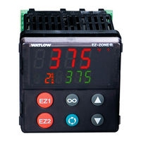
Watlow ez-zone pm User Manual (256 pages)
Integrated Controllers
Brand:
Watlow
| Category:
Controller
| Size: 11 MB
Table of Contents
Table of Contents
5
Chapter 1: Overview
10
Available EZ-ZONE PM Literature and Resources
10
Introduction
11
Getting Started Quickly
13
A Conceptual View of the PM
14
Inputs
14
Internal Functions
15
Outputs
15
Input Events and Output Events
15
What Is a Profile
15
Chapter 2: Install and Wire
24
Dimensions
24
1/16 DIN (PM6) Dimensions
24
1/16 DIN (PM6) Recommended Panel Spacing
24
1/8 DIN (PM8) Vertical Dimensions
25
1/8 DIN (PM8) Vertical Recommended Panel Spacing
25
1/8 DIN (PM9) Horizontal Recommended Panel Spacing
26
1/4 DIN (PM4) Dimensions
27
1/4 DIN (PM4) Recommended Panel Spacing
27
Installation
28
Wiring
30
PM Integrated Isolation Block
34
Chapter 3: Keys and Displays
59
Responding to a Displayed Message
60
Default Home Page Parameters
61
Chapter 4: Home Page
61
Changing the Set Point
63
Starting a Profile from the Home Page
63
Ending a Profile from the Home Page
63
Modifying the Home Page
63
Conventions Used in the Menu Pages
67
Display
68
Communication Protocols
68
Modbus Introduction to the Modbus Protocol
68
J1939 Can
69
Profibus DP
70
Chapter 5: Operations Page
71
Analog Input Menu
74
Linearization Menu
76
Process Value Menu
77
Alarm Menu
85
Current Menu
87
Timer Menu
88
Math Menu
91
Special Output Function Menu
91
Profile Status Menu
93
Chapter 6: Setup Page
96
Analog Input Menu
100
Digital Bus Menu (J1939 CAN)
103
Linearization Menu
107
Process Value Menu
111
Digital Input/Output Menu
112
Limit Menu
118
Control Loop Menu
120
Output Menu
129
Alarm Menu
132
Current Menu
137
Timer Menu
138
Math Menu
141
Special Output Function Menu
142
Function Key
144
Global Menu
146
Communications Menu
149
Standard Bus
150
Modbus RTU
150
Devicenet
152
J1939 CAN Bus (Digital Input Bus)
153
Profibus DP
154
Modbus TCP or Ethernet/Ip
155
Real Time Clock Menu
159
Chapter 7: Profiling Page
160
Profile Setup
160
Starting a Profile
161
Profiling Menu
165
Chapter 8: Factory Page
172
Custom
174
Lock Menu
175
Unlock Menu
177
Diagnostics Menu
178
Calibration Menu
180
Chapter 9: Features
183
Changing PM Integrated Model Number to PM Express
185
Saving and Restoring Settings
186
Tuning the PID Parameters
187
Autotune
187
Manual Tuning
188
Autotuning with TRU-TUNE
188
Inputs
189
Calibration Offset
189
Calibration
190
Filter Time Constant
192
Sensor Selection
192
Sensor Backup
192
Set Point Minimum and Maximum
192
Scale High and Scale Low
192
Range High and Range Low
193
Receiving a Remote Set Point
193
Ten Point Linearization
194
Outputs
194
Duplex
194
NO-ARC Relay
194
Retransmitting a Process Value or Set Point
195
Cool Output Curve
196
Resetting a Tripped Limit
196
Control Methods
197
Output Configuration
197
Auto (Closed Loop) and Manual (Open Loop) Control
197
On-Off Control
198
Proportional and (P) Control
199
Proportional and Integral (PI) Control
199
Proportional, Integral and Derivative (PID) Control
200
Dead Band
200
Variable Time Base
201
Single Set Point Ramping
202
Cascade Control
202
Compressor Control
202
Differential Control
203
Ratio Control
203
Duplex Control
203
Motorized Valve Control
203
Chapter 9: Features
203
Timer Function
204
Setting up the Timer Function
204
Alarms
206
Process and Deviation Alarms
207
Set Points
207
Hysteresis
207
Latching
207
Silencing
208
Blocking
208
Current Sensing
208
Open and Shorted Load Circuit Detection
208
Open Loop Detection
209
Programming the EZ Key/S
209
Using Lockout and Password Security
210
Using Lockout Method 1 (Read and Set Lock)
210
Using Lockout Method 2 (Password Enable)
212
Modbus - Using Programmable Memory Blocks
214
CIP - Communications Capabilities
214
CIP Implicit Assemblies
215
PCCC - (Programmable Controller Communications Commands)
216
Profibus DP - (Decentralized Peripherals)
217
Software Configuration
217
Using EZ-ZONE Configurator Software
217
Chapter 10: Applications
221
Example 1: Single Loop Control
221
Example 2: Sensor Backup
221
Example 3: Square Root
222
Example 4: Ratio
222
Example 5: Differential
223
Example 6: Cascade
223
Example 7: Wet Bulb / Dry Bulb
225
Example 8: Vaisala
226
Example 9: Motorized Valve Control
227
Chapter 11: Appendix
229
Troubleshooting Alarms, Errors and Control Issues
229
Modbus - Programmable Memory Blocks
236
CIP Implicit Assembly Structures
239
CIP Implicit Assembly
239
Originator (Master) to Target (PM)
239
CIP Implicit Assembly
240
Target (PM) to Originator (Master)
240
Compact Class Assembly Structure
241
PM Specifications
248
Ordering Information for PM Integrated Controller Models
254
How to Reach Us
256
Advertisement
Watlow ez-zone pm User Manual (134 pages)
integrated controller models
Brand:
Watlow
| Category:
Controller
| Size: 7 MB
Table of Contents
Safety Information
2
Technical Assistance
2
Return Material Authorization (RMA)
3
Table of Contents
4
Chapter 1: Overview
5
Optional Features and Benefits
5
Standard Features and Benefits
5
A Conceptual View of the PM
7
Input Functions
7
Internal Functions
7
Output Functions
7
Current Monitoring
8
EZ-ZONEPM Integrated Model 1/16 DIN System Diagram with a Current Transformer, Without Communications Card (Slot B)
8
EZ-ZONEPM Integrated Model 1/16 DIN System Diagram with Auxillary Input, Without Communications Card (Slot B)
9
EZ-ZONEPM Integrated Model 1/16 DIN with Limit, System Diagram Without Communications Card (Slot B)
10
EZ-ZONEPM Integrated Model 1/16 DIN System Diagram with Expanded Communications (Slot B)
11
EZ-ZONEPM Integrated Model 1/8 and 1/4 DIN System Diagram Without 6 Digital I/O (Slot D), Without Communications (Slot E)
12
EZ-ZONEPM Integrated Model 1/8 and 1/4 DIN System Diagram with 6 Digital I/O (Slot D), Without Communications (Slot E)
13
EZ-ZONEPM Integrated Model 1/8 and 1/4 DIN with CT System Diagram Without 6 Digital I/O (Slot D), Without Communications (Slot E)
14
EZ-ZONEPM Integrated Model 1/8 and 1/4 DIN System Diagram Without 6 Digital I/O (Slot D), with Communications (Slot E)
15
1/16 DIN (PM6) Dimensions
16
1/16 DIN (PM6) Recommended Panel Spacing
16
Chapter 2: Install and Wire
16
1/8 DIN (PM8) Vertical Dimensions
17
1/8 DIN (PM8) Vertical Recommended Panel Spacing
17
1/8 DIN (PM9) Horizontal Dimensions
18
1/8 DIN (PM9) Horizontal Recommended Panel Spacing
18
1/4 DIN (PM4) Dimensions
19
1/4 DIN (PM4) Recommended Panel Spacing
19
Installing and Removing the PM EZ-ZONE PM (PM6 & PM8 Shown Below)
20
Removing the Mounted Controller from Its Case
20
Returning the Controller to Its Case
20
Chemical Compatibility
21
PM Integrated Isolation Block
24
Digital Input 5 - 6
25
High Power
25
Low Power
25
Digital Input 7 - 12
26
Input 1, 2 RTD
26
Input 1, 2 Thermocouple
26
Input 1, 2 Process
27
Input 1, 2 Thermistor
27
Input 1,2 Potentiometer
27
Input 2 Current Transformer
27
Digital Output 5 - 6
28
Digital Output 7 - 12
28
Output 1, 3 Mechanical Relay, Form C
29
Output 1, 3 Switched DC/Open Collector
29
Output 1, 3 Universal Process
29
Output 1, 3 Solid-State Relay, Form a
30
Output 2, 4 NO-ARC Relay, Form a
30
Output 2, 4 Switched DC
30
Output 2, 4 Mechanical Relay, Form a
31
Output 2, 4 Solid-State Relay, Form a
31
Quencharc Wiring Example
31
EIA-232/485 Modbus RTU Communications
32
Modbus RTU or Standard Bus EIA-485 Communications
32
Standard Bus EIA-485 Communications
32
Devicenet™ Communications
33
Ethernet/Ip™ and Modbus TCP Communications
33
Profibus DP Communications
33
Wiring a Serial EIA-485 Network
34
Chapter 3: Keys and Displays
35
Attention Codes
36
Navigating the EZ-ZONE PM Integrated Controller
36
Responding to a Displayed Message
36
Chapter 4: Home Page
38
Default Home Page Parameters
38
Modifying the Display Pairs
38
Communication Protocols
40
Conventions Used in the Menu Pages
40
Display
40
Range
40
Common Industrial Protocol (CIP) Devicenet & Ethernet/Ip
41
Data Types Used with CIP
41
Profibus DP
41
Chapter 5: Operations Page
42
Navigating the Operations Page
42
Chapter 6: Setup Page
58
Navigating the Setup Page
58
Chapter 7: Profiling Page
91
How to Start a Profile
91
Navigating the Profiling Page
91
Profiling Parameters
91
Chapter 8: Factory Page
95
Navigating the Factory Page
95
Chapter 9: Features
102
Autotuning
103
Saving and Restoring User Settings
103
Tuning the PID Parameters
103
Autotuning with TRU-TUNE+
104
Before Tuning
104
How to Autotune a Loop
104
Manual Tuning
104
Calibration
105
Calibration Offset
105
Inputs
105
Filter Time Constant
106
Sensor Backup
106
Sensor Selection
106
Set Point Low Limit and High Limit
106
Duplex
107
NO-ARC Relay
107
Outputs
107
Receiving a Remote Set Point
107
Auto (Closed Loop) and Manual (Open Loop) Control
108
Control Methods
108
Cool Output Curve
108
Output Configuration
108
On-Off Control
109
Control
110
Dead Band
110
Proportional Plus Integral (PI) Control
110
Proportional Plus Integral Plus Derivative (PID)
110
Single Set Point Ramping
111
Variable Time Base
111
Cascade Control
112
Compressor Control
112
Differential Control
113
Duplex Control
113
Ratio Control
113
Alarm Hysteresis
114
Alarm Set Points
114
Alarms
114
Process and Deviation Alarms
114
Alarm Blocking
115
Current Sensing
115
Programming the EZ Key/S
115
Lockout Menu
116
Using Lockout to Hide Pages and Menus
116
Using Password Security
116
Differences between a User Without Password, User with Password and Administrator
117
How to Acquire Access to the Control
117
How to Enable Password Security
117
Chapter 10: Applications
118
Example 1: Single Loop Control
118
Example 2: Sensor Backup
118
Example 3: Square Root
118
Example 4: Ratio
118
Example 5: Differential
119
Example 6: Cascade
119
Example 7: Wet Bulb / Dry Bulb
119
Example 8: Vaisala
120
Chapter 11: Appendix
121
Troubleshooting Alarms, Errors and Control Issues
121
Specifications
124
Ordering Information for PM Integrated Controller Models
126
Index
127
Advertisement
Related Products
Watlow EZ-ZONE PM Series
Watlow EZ-ZONE RMC
Watlow EZ-ZONE PM L AAAAB Series
Watlow EZ-ZONE PM L AAAB Series
Watlow EZ-ZONE PM L C AAAB Series
Watlow EZ-ZONE PM L E AAAB Series
Watlow EZ-ZONE PM L J AAAB Series
Watlow EZ-ZONE RM
Watlow EZ-ZONE ST
Watlow Eurotherm Nanodac
Watlow Categories
Controller
Heater
Temperature Controller
Control Unit
Data Loggers
More Watlow Manuals
Login
Sign In
OR
Sign in with Facebook
Sign in with Google
Upload manual
Upload from disk
Upload from URL