Sign In
Upload
Manuals
Brands
WATERKOTTE Manuals
Heat Pump
EcoTouch Ai1 Air
WATERKOTTE EcoTouch Ai1 Air Manuals
Manuals and User Guides for WATERKOTTE EcoTouch Ai1 Air. We have
2
WATERKOTTE EcoTouch Ai1 Air manuals available for free PDF download: Planning And Installation, Planning And Installation Manual
WATERKOTTE EcoTouch Ai1 Air Planning And Installation (80 pages)
Zudaban and Power Inverter. Heating Station.
Brand:
WATERKOTTE
| Category:
Heating System
| Size: 5.78 MB
Table of Contents
Table of Contents
3
1 Safety
6
Intended Use
6
Basic Safety Precautions
6
Keep Information Available
6
Before Initial Use
6
Environmental Protection
7
Modifications and Repairs on the Heat Pump
7
Hazards
8
Operator's Duty of Care
9
Other Applicable Documents
9
2 Functional Principle of Heat Pumps
10
3 Product Description and Scope of Delivery
11
Overview
11
Scope of Delivery
12
Heat Distribution Station Ecotouch Ai1 Air
12
Domestic Hot Water Tank
12
4 Components and Setup
13
Heat Distribution Station Ecotouch Ai1 Air
13
Construction and Controlling
13
Electronic Heat Pump Control
13
Outdoor Unit (Heat Source)
14
Overview: Ecotouch Ai1 Air
14
Connection Accessories
15
Sensor System
15
Heat Meter (Optional)
15
5 Transport
16
6 Installation and Connection
17
Installation and Connection of Indoor Unit
17
Environmental Conditions for Installation
18
Installation of the Heat Pump
18
Preparation of the Assembly
18
Assembly of the Heat Pump
19
Connection Tube of the Tank (at the Top)
20
Connection Tube of the Tank (Bottom)
20
Connection Terminal
21
Installation of the Temperature Sensor
22
Installation of the Touch Display
23
Installation of the Housing
24
Removing the Housing
25
7 Installation and Connection
26
Connections (Rear)
26
Connection Measurements
27
8 Installation and Connection of Outdoor Unit
28
Selecting a Location for Outdoor Unit
28
Dimensions of Outdoor Unit
29
Clearance for Ventilation and Operation
30
Mounting on Base Plate or on the Wall
30
Installation and Space Requirement
31
Connection Outdoor Unit / Indoor Unit (Refrigerant Lines)
32
Installation of Refrigerant Lines
32
Connections Indoor Unit (Refrigerant Line)
33
Connections Outdoor Unit (Refrigerant Line)
33
Installation of a LOKRING Coupling (Example)
34
Tube Airtight Testing Method (Recommended Procedure)
36
9 Refrigerant
37
Requirements on Handling of R410A Refrigerant
37
Safety Information on Handling of Refrigerant
37
Refrigerant Charge and Additional Charge - Ecotouch Ai1 Air (Zubadan)
38
Refrigerant Charge and Additional Charge - Ecotouch Ai1 Air (Power Inverter)
39
Charging Refrigerant Circuit
40
Adding Refrigerant
41
Insulation
41
10 Electrical Work
42
Electrical Connection Outdoor Unit
43
Electrical Connection Indoor Unit
44
Connection Temperature Sensor
44
Connection Touch Display
44
Installing External Wall Sensor
44
Adjustment of the Electrical Heating Element
44
Connection Diagram
45
Ecotouch Ai1 Air Zubadan and Power Inverter: Overview Clamps (400 V)
45
Ecotouch Ai1 Air Zubadan and Power Inverter: Overview Clamps (230 V)
46
Ecotouch Ai1 Air Zubadan and Power Inverter: Overview Clamps
47
(Compressor 230 V / Electrical Resistance Heating 400 V)
47
Ecotouch Ai1 Air Zubadan and Power Inverter: Overview Clamps X1 (All Models)48
48
Ecotouch Ai1 Air Zubadan and Power Inverter: Overview Clamps X2 (All Models)49
49
Ecotouch Ai1 Air Zubadan and Power Inverter: Overview Clamps X4 (All Models)50
50
Ecotouch Ai1 Air Zubadan and Power Inverter: Input (400 V)
51
Ecotouch Ai1 Air Zubadan and Power Inverter: Input (230 V)
52
Ecotouch Ai1 Air Zubadan and Power Inverter: Input (Compressor 230 V / Electrical Resistance Heating 400 V)
53
Ecotouch Ai1 Air Zubadan and Power Inverter: Electric Heating Insert (400 V)
54
Ecotouch Ai1 Air Zubadan and Power Inverter: Electric Heating Insert (230 V)
55
Ecotouch Ai1 Air Zubadan and Power Inverter: Control Power (All Models)
56
Ecotouch Ai1 Air Zubadan and Power Inverter: Control Source and Heating Pump (400 V and 230 V)
57
Ecotouch Ai1 Air Zubadan and Power Inverter: Switched Output Extern (400 V and 230 V)
58
Ecotouch Ai1 Air Zubadan and Power Inverter: Digital Output Extern (400 V and 230 V)
59
Ecotouch Ai1 Air Zubadan and Power Inverter: Analoque Signals Extern
60
And 230 V)
60
Ecotouch Ai1 Air Zubadan and Power Inverter: Expansion Valve, BUS and Display (230 V and 400 V)
61
Ecotouch Ai1 Air Zubadan and Power Inverter: Intern Control Board (400 V and 230 V)
62
Ecotouch Ai1 Air Zubadan and Power Inverter: WWPR 2 (400 V and 230 V)
63
DIP Switch of Motherboard (Indoor Unit)
64
11 Silent Mode (Option)
65
Connecting „Silent Mode
66
Silent Mode (Only the Fan Speed Reduction)
67
Step Mode (Speed Reduction of Fan and Compressor)
67
12 Start-Up
68
Pre-Startup Checks
68
Initial Start of the Heat Pump
71
Control of Entire Operation
71
Turning Heat Pump off
72
Taking Heat Pump out of Operation for Extended Period
72
13 Defrost Operation
72
Start
72
14 Maintenance and Care
73
15 Technical Data
74
Ecotouch Ai1 Air (Zubadan)
74
Ecotouch Ai1 Air (Power Inverter)
75
16 Connection Diagram
76
Ecotouch Ai1 Air with Underfloor Heating (Basic Circuit Diagram)
76
Ecotouch Ai1 Air with Underfloor Heating and Single Room Control (Basic Circuit Diagram)
76
Ecotouch Ai1 Air with Radiators or Fan Convectors (Basic Circuit Diagram)
77
Ecotouch Ai1 Air with Hydraulic Filter (Basic Circuit Diagram)
77
Overview Ecotouch Ai1 Air
78
Advertisement
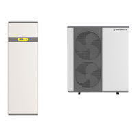
WATERKOTTE EcoTouch Ai1 Air Planning And Installation Manual (60 pages)
Air to water heat pump
Brand:
WATERKOTTE
| Category:
Heat Pump
| Size: 5.13 MB
Table of Contents
Table of Contents
3
1 Safety
5
Intended Use
5
Basic Safety Precautions
5
Keep Information Available
5
Before Initial Use
5
Environmental Protection
6
Modifications and Repairs on the Heat Pump
6
Hazards
6
Operator's Duty of Care
8
Other Applicable Documents
8
2 Product Description and Scope of Delivery
9
Overview
9
Basic Line Ai1 Air /BS 7010 (Outdoor Module)
10
Basic Line Ai1 Air (Indoor Module)
10
Basic Line BS Hyd 5010 Hydraulic Station
10
3 Components and Installation
11
Heating System Basic Line Ai1 Air BS 7010 / BS 7006
11
Structure and Control
11
Electronic Heat Pump Control
11
4 Transport to Installation Site
12
Environmental Conditions for Installation (Indoor Module)
12
Residual Head Circulation Pump (Heating)
12
5 Installation and Connection
13
Installation and Connection of Indoor Unit
13
Environmental Conditions for Installation
13
Dimensions and Connections Outdoor Module BS 7010 (5010.5)
14
Dimensions and Connections Outdoor Module BS 7006 (5006.5)
15
Dimensions and Connections (Indoor Module) Basic Line Ai1 Air
16
Dimensions and Connections (Indoor Module) BS Hyd 5010 Hydraulic Station
17
Installation of Cover and Cladding Panels
18
Disassembly of Cladding Panels
18
Disassembly of Cover and Cladding Panels (Outdoor Module)
18
6 Installation and Connection of the Outdoor Module
19
Selecting a Location for Outdoor Module
19
Clearance for Ventilation and Operation
20
Installation in Base Plate or on the Wall
20
Installation and Space Requirement
21
7 Connection Lines
22
Refrigerant Charge and Additional Charge
22
Oil Traps
23
Insulation
23
Tube Airtight Testing Method (Recommended Procedure), Test Equipment Nitrogen24
24
Connection Outdoor Module / Indoor Module (Refrigerant Lines) Basic Line Ai1 Air
25
Connections (Refrigerant and Heating) Indoor Module Hydraulic Station
26
Connections Outdoor Module (Refrigerant Line)
27
8 Refrigerant
28
Requirements on Handling of R410A Refrigerant
28
Safety Guidelines for the Handling of Refrigerants
28
Charging Refrigerant Circuit
29
Mounting (Heating /Domestic Water Side)
30
9 Electrical Work
31
Electrical Connection Outdoor Module
32
Cable Cross Sections/Types
32
Electrical Connection (Indoor Module) (Hydraulic Station / Control Module)
32
Installing External Wall Sensor
32
Power Supply- Heating Element
32
Heating Element - Thermostat Setting
32
Electrical and BUS Connection (Outdoor Module BS 7010.5)
33
Electrical and BUS Connection (Outdoor Module, BS 7006.5)
34
Electrical Connection Basic Line Ai1 Air (5010.5) (Indoor Module)
35
Electrical and BUS Connection Basic Line BS Hyd 5010 Hydraulic Station
35
DIP-Switch (Outdoor Module)
35
Electrical Wiring Diagram Basic Line Ai1 Air / BS 7010 (Outdoor Module)
36
Electrical Wiring Diagram - Basic Line Ai1 Air (Indoor Module)
37
Electrical Wiring Diagram - Basic Line BS Hyd 5010 Hydraulic Station (Indoor Module)
38
WWPR2 Controler - Connections
39
Electrical Connections
40
10 Commissioning
41
Pre-Startup Checks
41
Initial Start of Heat Pump
43
Control of Entire Operation
44
Turning Heat Pump off
44
Taking Heat Pump out of Operation for Extended Period
44
11 Technical Data
45
12 Connection Diagram
46
Basic Line Ai1 Air with Underfloor Heating, Without Single Room Control
46
Basic Line Ai1 Air with Underfloor Heating, with Single Room Control
47
Basic Line Ai1 Air with Radiators / Fan Convectors
48
Basic Line Ai1 Air with Hydraulic Compensator
49
Basic Line Ai1 Air Hydraulic Compensator and Additional Heater
50
Basic Line BS 7010 with Underfloor Heating, Without Single Room Control
51
Basic Line BS 7010 with Underfloor Heating, Without Single Room Control, Decentral Domestic Hot Water Preparation
52
Legend (Hydraulic Schemes)
53
13 Refrigeration Circuit Basic Line Ai1 Air / BS 7010
55
14 Maintenance and Inspection
57
Advertisement
Related Products
WATERKOTTE EcoTouch Ai1 Geo
WATERKOTTE EcoTouch DS 5018 Ai
WATERKOTTE EcoTouch DS 5050T
WATERKOTTE EcoTouch DS 5028.5
WATERKOTTE EcoTouch DS 5045.5T
WATERKOTTE EcoTouch DS 5034.5T
WATERKOTTE EcoTouch DS 5056.5T
Waterkotte EcoTouch DS 5027 Ai
WATERKOTTE Basic Line BS 7006
WATERKOTTE Basic Line BS 7010
WATERKOTTE Categories
Heating System
Heat Pump
Water Heater
More WATERKOTTE Manuals
Login
Sign In
OR
Sign in with Facebook
Sign in with Google
Upload manual
Upload from disk
Upload from URL