Table of Contents
Advertisement
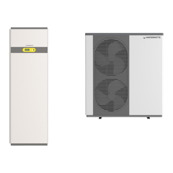
Basic Line Ai1 Air – Indoor unit
Basic Line BS7010 – Hydraulikstation
- Indoor unit
WATERKOTTE GmbH, Gewerkenstraße 15, D-44628 Herne
Tel.: 0049/(0)2323/9376-0, Fax: 0049/(0)2323/9376-99, E-Mail: info@waterkotte.de
Planning and installation
Basic Line Ai1 Air /Basic Line BS 7010
Basic Line Ai1 Air /Basic Line BS 7006
Internet: http://www.waterkotte.de
Basic Line Ai1 Air
Air to water heat pump
- Outdoor unit
- Outdoor unit
21.10.2015 / Z21437
Advertisement
Table of Contents

Related Manuals for WATERKOTTE Basic Line BS 7010


Summary of Contents for WATERKOTTE Basic Line BS 7010
- Page 1 Planning and installation Basic Line Ai1 Air Air to water heat pump Basic Line Ai1 Air /Basic Line BS 7010 - Outdoor unit Basic Line Ai1 Air – Indoor unit Basic Line Ai1 Air /Basic Line BS 7006 - Outdoor unit Basic Line BS7010 –...
- Page 2 This publication has been prepared with all reasonable care. WATERKOTTE GmbH does not assume any liability for remaining errors or omissions, or for possible damages. Note: This symbol applies only to countries within the European Union (EU).
-
Page 3: Table Of Contents
Tube airtight testing method (recommended procedure), test equipment nitrogen24 Connection outdoor module / indoor module (refrigerant lines) Basic Line Ai1 Air .... 25 Connections (refrigerant and heating) indoor module hydraulic station ......26 3 / 60 21.10.2015 Copyright 2014 by: WATERKOTTE GmbH. Subject to changes. - Page 4 12.5 Basic Line Ai1 Air hydraulic compensator and additional heater ........50 12.6 Basic Line BS 7010 with underfloor heating, without single room control ......51 12.7 Basic Line BS 7010 with underfloor heating, without single room control, decentral domestic hot water preparation .........................
-
Page 5: Safety
1 Safety 1.1 Intended use Your WATERKOTTE heat pump of the Basic Line series is used for space heating and cooling, and heating of domestic water. An outdoor module, which is coupled to a heat source (air) that is available year-round, serves as heat generator. -
Page 6: Environmental Protection
Original parts are specifically designed for your heat pump. Externally pro- cured parts provide no guarantee that they are designed and manufactured in compliance with relevant usage and safety requirements. Parts and special equipment not delivered by WATERKOTTE are not ap- proved for use on the heat pump. 1.3 Hazards... - Page 7 Repeated restart of the heat pump can result in total loss! In case of heat pump failure, an inspection by qualified and authorised personnel must be performed before restart. 7 / 60 21.10.2015 Copyright 2014 by: WATERKOTTE GmbH. Subject to changes.
-
Page 8: Operator's Duty Of Care
Safety 1.4 Operator's duty of care Your WATERKOTTE heat pump has been designed and built on the basis of a risk analysis and after careful selection of standards to be observed. Thus, your heat pump is state-of-the-art and provides for maximum safety. -
Page 9: Product Description And Scope Of Delivery
Basic Line Ai1 Air /BS 7010 - (outdoor module) Basic Line Ai1 Air /BS 7006 - (outdoor module) Basic Line Ai1 Air - (indoor module) Basic Line BS Hyd 5010 hydraulic station – (indoor module) 9 / 60 21.10.2015 Copyright 2014 by: WATERKOTTE GmbH. Subject to changes. -
Page 10: Basic Line Ai1 Air /Bs 7010 (Outdoor Module)
Series options Hydraulic station incl. control (only heating) - Art. Nr.: BS701059CH Hydraulic station incl. control (heating and domestic hot water) - Art. Nr.: BS701059CHW 10 / 60 21.10.2015 Copyright 2014 by: WATERKOTTE GmbH. Subject to changes. -
Page 11: Components And Installation
The control is used to control and monitor heating systems that are operat- ed with WATERKOTTE compact heat pumps according to technical guide- lines of WATERKOTTE Wärmepumpen GmbH. All tasks to do with control are fulfilled (depending on the external temperature, control, monitoring, self-diagnosis, saving of data in case of breakdown, etc. -
Page 12: Transport To Installation Site
4.2 Residual head circulation pump (heating) Residual head circulation pump (heating) - Hydraulic station BS Hyd 5010 - Indoor module Basic Line Ai1 Air 10 kW t=5K ∆ 12 / 60 21.10.2015 Copyright 2014 by: WATERKOTTE GmbH. Subject to changes. -
Page 13: Installation And Connection
+25 °C. To facilitate maintenance, the use of a base plate is recommended. To compensate for minor unevenness, we recommend use of an approx. 10 mm thick rubber mat. 13 / 60 21.10.2015 Copyright 2014 by: WATERKOTTE GmbH. Subject to changes. -
Page 14: Dimensions And Connections Outdoor Module Bs 7010 (5010.5)
5.3 Dimensions and connections outdoor module BS 7010 (5010.5) Figure 2: Dimensions outdoor module BS 7010 (all dimensions mm) Cable entries, electrical connection Cover: connection refrigerant line 14 / 60 21.10.2015 Copyright 2014 by: WATERKOTTE GmbH. Subject to changes. -
Page 15: Dimensions And Connections Outdoor Module Bs 7006 (5006.5)
5.4 Dimensions and connections outdoor module BS 7006 (5006.5) Figure 3: Dimensions outdoor module BS 7006 (all dimensions mm) Cable entries, electrical connection Cover: connection refrigerant line 15 / 60 21.10.2015 Copyright 2014 by: WATERKOTTE GmbH. Subject to changes. -
Page 16: Dimensions And Connections (Indoor Module) Basic Line Ai1 Air
Installation and connection 5.5 Dimensions and connections (indoor module) Basic Line Ai1 Air Figure 4: Dimensions indoor module Basic Line Ai1 Air (all dimensions mm 16 / 60 21.10.2015 Copyright 2014 by: WATERKOTTE GmbH. Subject to changes. -
Page 17: Dimensions And Connections (Indoor Module) Bs Hyd 5010 Hydraulic Station
Installation and connection 5.6 Dimensions and connections (indoor module) BS Hyd 5010 hydraulic station Figure 5: Dimensions indoor module (buttom) 17 / 60 21.10.2015 Copyright 2014 by: WATERKOTTE GmbH. Subject to changes. -
Page 18: Installation Of Cover And Cladding Panels
5.9 Disassembly of cover and cladding panels (outdoor module) Cover and cladding panels are fixed with screws. In the case of a disas- sembly the screws must be removed with an appropriate screwdriver. 18 / 60 21.10.2015 Copyright 2014 by: WATERKOTTE GmbH. Subject to changes. -
Page 19: Installation And Connection Of The Outdoor Module
Do not exceed permissible line length between indoor and outdoor module. Risk of injury! When carrying the module at the bottom there is a risk of crushing the hands / fingers. 19 / 60 21.10.2015 Copyright 2014 by: WATERKOTTE GmbH. Subject to changes. -
Page 20: Clearance For Ventilation And Operation
Ensure that the melted water can drain off. Ensure that the entire drain is frost-free to prevent freezing in the winter. For this purpose, a trace heating could be applied. 20 / 60 21.10.2015 Copyright 2014 by: WATERKOTTE GmbH. Subject to changes. -
Page 21: Installation And Space Requirement
6. In recess with roof, air outlet clear in front, flow obstacle at rear, on both sides and above. Figure 7: Space requirement and minimum distances for installation 21 / 60 21.10.2015 Copyright 2014 by: WATERKOTTE GmbH. Subject to changes. -
Page 22: Connection Lines
Do not exceed permissible line length LMAX (20 m)! If the maximum difference in height is achieved of 3 m, an oil trap at 1.5 m has to be provided. 22 / 60 21.10.2015 Copyright 2014 by: WATERKOTTE GmbH. Subject to changes. -
Page 23: Oil Traps
6 m, oil traps have to be installed every 6 m. 7.3 Insulation For refrigerant line we recommend the use of pre-insulated original WATERKOTTE double-copper tube rings 10 / 16 x 1.0 mm (Z16956) and matching screw clamps (Z16957). Recommendation:... -
Page 24: Tube Airtight Testing Method (Recommended Procedure), Test Equipment Nitrogen24
0.01 MPa (0.1 bar). Make the necessary correc- tions. 6. If the pressure drops during steps (2) or (3), a gas leak exists. Look for the source of the gas leak. 24 / 60 21.10.2015 Copyright 2014 by: WATERKOTTE GmbH. Subject to changes. -
Page 25: Connection Outdoor Module / Indoor Module (Refrigerant Lines) Basic Line Ai1 Air
Refrigerant line OUT copper pipe 10 mm (heat pump OUT Heating flow G1¼“, flat sealing Heating Return G1¼“, flat sealing Gauge pressure flow; G¾“int. boiler safety group (heating) 25 / 60 21.10.2015 Copyright 2014 by: WATERKOTTE GmbH. Subject to changes. -
Page 26: Connections (Refrigerant And Heating) Indoor Module Hydraulic Station
Heating Return G1¼“a, flachdichtend G1¼“a, flat sealing Refrigerant (gas side) 16 mm 16 mm Refrigerant (liquid side) 10 mm 10 mm Cold water (from tank) G1¼“, flat sealing 26 / 60 21.10.2015 Copyright 2014 by: WATERKOTTE GmbH. Subject to changes. -
Page 27: Connections Outdoor Module (Refrigerant Line)
Figure 10: refrigerant lines connections (flare connection) outdoor module 10 mm, liquide side 16 mm, gas side Note: If metric tubes are used as refrigerant line, you can use the adapter from the indoor modules. 27 / 60 21.10.2015 Copyright 2014 by: WATERKOTTE GmbH. Subject to changes. -
Page 28: Refrigerant
When removing the service hoses, do not point connections toward yourself. Residual refrigerant could escape. Never change factory setting of adjustment screw on expansion valve. 28 / 60 21.10.2015 Copyright 2014 by: WATERKOTTE GmbH. Subject to changes. -
Page 29: Charging Refrigerant Circuit
5. Open the two valves (1 a. 2) on the indoor module. The refrigerant flows into the entire system. 6. Disconnect the tube of the vacuum pump. 29 / 60 21.10.2015 Copyright 2014 by: WATERKOTTE GmbH. Subject to changes. -
Page 30: Mounting (Heating /Domestic Water Side)
The specifications of current drinking water regulations must be observed. Antifreeze has to be ensured for all pipes and fittings. 30 / 60 21.10.2015 Copyright 2014 by: WATERKOTTE GmbH. Subject to changes. -
Page 31: Electrical Work
Should it be necessary, disconnect all feed lines from the house fuse box. 31 / 60 21.10.2015 Copyright 2014 by: WATERKOTTE GmbH. Subject to changes. -
Page 32: Electrical Connection Outdoor Module
In case of trigger- ing, it must be reset manually. To reset use the button on the bottom of the safety temperature limiter (under the cap). 32 / 60 21.10.2015 Copyright 2014 by: WATERKOTTE GmbH. Subject to changes. -
Page 33: Electrical And Bus Connection (Outdoor Module Bs 7010.5)
9.3 Electrical and BUS connection (outdoor module BS 7010.5) Pos. Description BUS connection (use screened line) Terminals: A = + B = - GND = GND Electrical connection (230 V) 33 / 60 21.10.2015 Copyright 2014 by: WATERKOTTE GmbH. Subject to changes. -
Page 34: Electrical And Bus Connection (Outdoor Module, Bs 7006.5)
BUS connection (use screened line) Terminals : GND = GND B = - A = + 12 V = not connected - = Fan + = Fan Electrical connection (230 V) 34 / 60 21.10.2015 Copyright 2014 by: WATERKOTTE GmbH. Subject to changes. -
Page 35: Electrical Connection Basic Line Ai1 Air (5010.5) (Indoor Module)
In case of replacing or repairing: Check the position of the DIP switches on the main board (outdoor module). The correct switch position is shown on the wiring diagram (outdoor module). 35 / 60 21.10.2015 Copyright 2014 by: WATERKOTTE GmbH. Subject to changes. -
Page 36: Electrical Wiring Diagram Basic Line Ai1 Air / Bs 7010 (Outdoor Module)
Electrical work 9.7 Electrical wiring diagram Basic Line Ai1 Air / BS 7010 (outdoor module) 36 / 60 21.10.2015 Copyright 2014 by: WATERKOTTE GmbH. Subject to changes. -
Page 37: Electrical Wiring Diagram - Basic Line Ai1 Air (Indoor Module)
Electrical work 9.8 Electrical wiring diagram - Basic Line Ai1 Air (indoor module) 37 / 60 21.10.2015 Copyright 2014 by: WATERKOTTE GmbH. Subject to changes. -
Page 38: Electrical Wiring Diagram - Basic Line Bs Hyd 5010 Hydraulic Station (Indoor Module)
Electrical work 9.9 Electrical wiring diagram - Basic Line BS Hyd 5010 hydraulic station (indoor module) 38 / 60 21.10.2015 Copyright 2014 by: WATERKOTTE GmbH. Subject to changes. -
Page 39: Wwpr2 Controler - Connections
NO7 – MKV WW / Pumpe WW NO7 – MBV HW / Pump HW NO7 – Vanne ECS / pompe ECS NC7 - NC7 - NC7 - 39 / 60 21.10.2015 Copyright 2014 by: WATERKOTTE GmbH. Subject to changes. -
Page 40: Electrical Connections
Electrical work 9.11 Electrical connections 40 / 60 21.10.2015 Copyright 2014 by: WATERKOTTE GmbH. Subject to changes. -
Page 41: Commissioning
Use circuit breakers (ground fault interrupter, isolating switch (+B fuse), and moulded case circuit breaker) with the specified capacity. Failure of 41 / 60 21.10.2015 Copyright 2014 by: WATERKOTTE GmbH. Subject to changes. - Page 42 Check also the solidification point of the water-glycol mixture. It must be below the expected minimum temperature of the medium. Risk of total loss! Do not start module if insulation resistance is below 1.0 MΩ. 42 / 60 21.10.2015 Copyright 2014 by: WATERKOTTE GmbH. Subject to changes.
-
Page 43: Initial Start Of Heat Pump
(Kap. 10), proceed as follows: 1. Turn on main power switch (on heat pump) The compressor does not start immediately, because the oil dump 43 / 60 21.10.2015 Copyright 2014 by: WATERKOTTE GmbH. Subject to changes. -
Page 44: Control Of Entire Operation
10.5 Taking heat pump out of operation for extended period - see 10.4- Total loss (freezing) At low outdoor temperatures the device and the pipes must be protected from freezing. 44 / 60 21.10.2015 Copyright 2014 by: WATERKOTTE GmbH. Subject to changes. -
Page 45: Technical Data
Technical data 11 Technical data Basic Line Ai1 Air / Basic Line BS 7010 5006.5 5010.5 Heating capacity (A-7/W35) Power consumption COP (A-7/W35) EN14511 Heating capacity (A2/W35) 10.8 Power consumption 3.54 3.55 COP (A2/W35) controlled (EN14511) (controlled at 4.5 kW) (controlled at 6.7 kW) -
Page 46: Connection Diagram
Connection diagram 12 Connection diagram 12.1 Basic Line Ai1 Air with underfloor heating, without single room control 46 / 60 21.10.2015 Copyright 2014 by: WATERKOTTE GmbH. Subject to changes. -
Page 47: Basic Line Ai1 Air With Underfloor Heating, With Single Room Control
Connection diagram 12.2 Basic Line Ai1 Air with underfloor heating, with single room control 47 / 60 21.10.2015 Copyright 2014 by: WATERKOTTE GmbH. Subject to changes. -
Page 48: Basic Line Ai1 Air With Radiators / Fan Convectors
Connection diagram 12.3 Basic Line Ai1 Air with radiators / fan convectors 48 / 60 21.10.2015 Copyright 2014 by: WATERKOTTE GmbH. Subject to changes. -
Page 49: Basic Line Ai1 Air With Hydraulic Compensator
Connection diagram 12.4 Basic Line Ai1 Air with hydraulic compensator 49 / 60 21.10.2015 Copyright 2014 by: WATERKOTTE GmbH. Subject to changes. -
Page 50: Basic Line Ai1 Air Hydraulic Compensator And Additional Heater
Connection diagram 12.5 Basic Line Ai1 Air hydraulic compensator and additional heater 50 / 60 21.10.2015 Copyright 2014 by: WATERKOTTE GmbH. Subject to changes. -
Page 51: Basic Line Bs 7010 With Underfloor Heating, Without Single Room Control
Connection diagram 12.6 Basic Line BS 7010 with underfloor heating, without single room control 51 / 60 21.10.2015 Copyright 2014 by: WATERKOTTE GmbH. Subject to changes. -
Page 52: Basic Line Bs 7010 With Underfloor Heating, Without Single Room Control, Decentral Domestic Hot Water Preparation
Connection diagram 12.7 Basic Line BS 7010 with underfloor heating, without single room control, decen- tral domestic hot water preparation 52 / 60 21.10.2015 Copyright 2014 by: WATERKOTTE GmbH. Subject to changes. -
Page 53: Legend (Hydraulic Schemes)
Pool heat exchanger Ball valve Optimised thermal tank with integrated smooth pipe heat exchanger Geothermal energy probes Compact condensing boiler 1000 l to 2500 l Thermostat valve Temperature controller 53 / 60 21.10.2015 Copyright 2014 by: WATERKOTTE GmbH. Subject to changes. - Page 54 Motor-driven changeover ball valve (pool) Multilayer filter for pool water cleaning Pool water - disinfection system PH value control and correction system Pool water drain Pool water circulation pump 54 / 60 21.10.2015 Copyright 2014 by: WATERKOTTE GmbH. Subject to changes.
-
Page 55: Refrigeration Circuit Basic Line Ai1 Air / Bs 7010
13 Refrigeration circuit Basic Line Ai1 Air / BS 7010 Figure 12: Refrigeration circuit Basic Line Ai1 Air Figure 13: Refrigeration circuit Basic Line Ai1 Air with hot water tank 55 / 60 21.10.2015 Copyright 2014 by: WATERKOTTE GmbH. Subject to changes. - Page 56 Expansion valve Electronic Evaporator Heat exchanger (lamellae) Flüssigkeitsabscheider Refrigerant receiver Valve (hot water) Electrical heating element Circulation pump Hot water tank Security group Heating side Hot water side 56 / 60 21.10.2015 Copyright 2014 by: WATERKOTTE GmbH. Subject to changes.
-
Page 57: Maintenance And Inspection
Maintenance and inspection 14 Maintenance and inspection Have your WATERKOTTE heat pump maintained annually. This will ensure the operational safety and efficiency of your heat pump. Additional infor- mation is available from your WATERKOTTE service partner. During maintenance, the technical condition of the heat pump system is checked as well (target / actual comparison). - Page 58 Maintenance and inspection 58 / 60 21.10.2015 Copyright 2014 by: WATERKOTTE GmbH. Subject to changes.
- Page 59 Maintenance and inspection 59 / 60 21.10.2015 Copyright 2014 by: WATERKOTTE GmbH. Subject to changes.
- Page 60 Maintenance and inspection WATERKOTTE GmbH, Gewerkenstraße 15, D-44628 Herne Tel.: 0049/(0)2323/9376-0, Fax: 0049/(0)2323/9376-99, Service: 0049/(0)2323/9376-350 E-Mail: info@waterkotte.de Internet: http://www.waterkotte.de 60 / 60 21.10.2015 Copyright 2014 by: WATERKOTTE GmbH. Subject to changes.
Need help?
Do you have a question about the Basic Line BS 7010 and is the answer not in the manual?
Questions and answers