Sign In
Upload
Manuals
Brands
WAGO Manuals
Control Unit
750-517/040-000
User Manuals: WAGO 750-517/040-000 Output Terminal
Manuals and User Guides for WAGO 750-517/040-000 Output Terminal. We have
1
WAGO 750-517/040-000 Output Terminal manual available for free PDF download: Manual
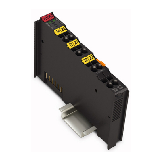
WAGO 750-517/040-000 Manual (58 pages)
2DO 230V AC 1.0A/ Relay 2CO /XTR 2-Channel Relay Output Module 230 VAC, 1.0 A, 2 Changeover Contacts /XTR For WAGO-I/O-SYSTEM 750 XTR
Brand:
WAGO
| Category:
Control Unit
| Size: 2 MB
Table of Contents
Deutsch
3
Table of Contents
3
Validity of this Documentation
5
Copyright
5
Notes about this Documentation
5
Symbols
6
Number Notation
8
Font Conventions
8
Table 1: Number Notation
8
Table 2: Font Conventions
8
Personnel Qualifications
9
Use of the 750 Series in Compliance with Underlying Provisions
9
Subject to Changes
9
Legal Bases
9
Important Notes
9
Technical Condition of Specified Devices
10
Disposal
10
2.1.4.1.1 Electrical and Electronic Equipment
10
2.1.4.1.2 Packaging
11
Safety Advice (Precautions)
12
Device Description
15
View
17
Figure 1: View
17
Table 3: Legend for Figure "View
17
Connectors
18
Data Contacts/Local Bus
18
Figure 2: Data Contacts
18
Table 4: Legend for Figure "CAGE CLAMP ® Connectors
19
Figure 3: CAGE CLAMP ® Connectors
19
Power Jumper Contacts/Field Supply
19
CAGE CLAMP ® Connectors
19
Display Elements
20
Operating Elements
20
Figure 4: Display Elements
20
Table 5: Legend for Figure "Display Elements
20
Schematic Diagram
21
Figure 5: Schematic Diagram
21
Table 6: Technical Data - Device
22
Table 7: Technical Data - Supply
22
Table 8: Technical Data - Communication
22
Communication
22
Supply
22
Device Data
22
Technical Data
22
Table 13: Technical Data - Mechanical Conditions
23
Table 12: Technical Data - Data Contacts
23
Table 11: Technical Data - Power Jumper Contacts
23
Table 10: Technical Data - Field Wiring
23
Table 9: Technical Data - Outputs
23
Mechanical Conditions
23
Connection Type
23
Outputs
23
Climatic Environmental Conditions
24
Load Limiting Curve
24
Figure 6: Load Limiting Curve of the Relay
24
Table 14: Technical Data - Climatic Environmental Conditions
24
Approvals
25
Table 15: Standards and Rated Conditions for Explosion Protection Applications
27
Standards and Guidelines
27
Table 16: Climatic and Mechanical Environmental Conditions and
28
Table 17: EMC - Immunity to Interference
29
Table 18: EMC - Emission of Interference
31
Table 19: Standards and Rated Conditions for Rail Applications (en 50155)
32
Process Image
33
Table 20: Output Bits
33
Mounting
34
Mounting Sequence
34
Inserting and Removing Devices
35
Inserting the I/O Module
35
Figure 7: Insert I/O Module (Example)
35
Figure 8: Snap the I/O Module into Place (Example)
36
Figure 9: Removing the I/O Module (Example)
37
Removing the I/O Module
37
Connect Devices
38
Connecting a Conductor to the CAGE CLAMP
38
Figure 10: Connecting a Conductor to a CAGE CLAMP
39
Connection Examples
40
1-Wire Connection, Protection Class I Actuators
40
1-Wire Connection, Protection Class II and III Actuators
40
Figure 11: Connection Example, 1-Wire Connection for Protection Class I
40
Figure 12: Connection Example 1-Wire Connection for Protection Class II (Double Insulated) and Class III (Safety Extra-Low Voltage) Actuators
40
Operating the Relay in Separate Current Circuits
41
Figure 13: Connection Example - Separate Current Circuits
41
Operating the Relay in Series Connection
42
Figure 14: Connection Example - Series Connection
42
Table 21: Protective Circuits for Contacts of Relay Modules
43
Figure 18: Varistor
43
Figure 16: Zener Diode and Diode
43
Figure 17: Suppressor Diode
43
Protective Circuits for Contacts of Relay Modules
43
Figure 15: Diode
43
Figure 19: R/C Combination
44
Use in Hazardous Environments
45
Marking Configuration Examples
46
Marking for Europe According to ATEX and Iecex
46
Figure 20: Marking Example According to ATEX and Iecex
46
Figure 21: Text Detail - Marking Example According to ATEX and Iecex
46
Table 22: Description of Marking Example According to ATEX and Iecex
47
Figure 22: Marking Example for Approved Ex I I/O Module According to
48
Figure 23: Text Detail - Marking Example for Approved Ex I I/O Module
48
Table 23: Description of Marking Example for Approved Ex I I/O Module According to ATEX and Iecex
49
Table 25: Description of Marking Example for Approved Ex I I/O Module
49
Table 24: Description of Marking Example According to NEC 500
50
Marking for the United States of America (NEC) and Canada (CEC)
50
Figure 25: Text Detail - Marking Example According to NEC 500
50
Figure 24: Marking Example According to NEC
50
Figure 26: Text Detail - Marking Example for Approved Ex I I/O Module
51
Figure 27: Text Detail - Marking Example for Approved Ex I I/O Module
51
Table 26: Description of Marking Example for Approved Ex I I/O Modules
51
Figure 28: Text Detail - Marking Example for Approved Ex I I/O Modules
52
Table 27: Description of Marking Example for Approved Ex I I/O Modules
52
Installation Regulations
53
Special Notes Regarding Explosion Protection
53
Special Notes Regarding ANSI/ISA Ex
55
English
56
List of Figures
56
List of Tables
57
Advertisement
Advertisement
Related Products
WAGO 750-511
WAGO 750-513 Series
WAGO 750-513/000-001
WAGO 750-515
WAGO WAGO-I/O-SYSTEM 750-508
WAGO 750-564
WAGO 750-535/040-000
WAGO 750-536
WAGO 750-528
WAGO 750-502
WAGO Categories
I/O Systems
Control Unit
Power Supply
Switch
Controller
More WAGO Manuals
Login
Sign In
OR
Sign in with Facebook
Sign in with Google
Upload manual
Upload from disk
Upload from URL