Sign In
Upload
Manuals
Brands
WAGO Manuals
Control Unit
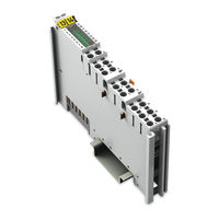
IO-Link Master 750-657
WAGO IO-Link Master 750-657 Manuals
Manuals and User Guides for WAGO IO-Link Master 750-657. We have
1
WAGO IO-Link Master 750-657 manual available for free PDF download: Manual
WAGO IO-Link Master 750-657 Manual (150 pages)
Brand:
WAGO
| Category:
Control Unit
| Size: 3 MB
Table of Contents
Deutsch
5
Table of Contents
3
Table of Contents
5
1 Notes about this Documentation
7
Validity of this Documentation
7
Copyright
7
Symbols
8
Number Notation
10
Font Conventions
10
Table 1: Number Notation
10
Table 2: Font Conventions
10
2 Important Notes
11
Legal Bases
11
Subject to Changes
11
Personnel Qualifications
11
Use of the 750 Series in Compliance with Underlying Provisions
11
Technical Condition of Specified Devices
12
Safety Advice (Precautions)
13
3 The IO-Link Technology
15
4 Device Description
16
Table 3: Compatibility List 750-657
17
View
19
Table 4: Caption Acc. to Figure "View
20
Connectors
21
Data Contacts/Internal Bus
21
Power Jumper Contacts/Field Supply
22
Table 5: Power Jumper Contacts
22
CAGE CLAMP Connections
23
Table 6: Connections
23
Display Elements
24
Table 7: Display Elements
24
Schematic Diagram
25
Technical Data
26
Device Data
26
Supply
26
Communication
26
Table 8: Technical Data - Device
26
Table 9: Technical Data - Supply
26
Table 10: Technical Data - Communication
26
IO-Link Ports
27
Table 11: Technical Data - IO-Link Ports
27
Approvals
29
Standards and Guidelines
30
5 Function Description
31
Parameter Model of the IO-Link Master
32
6 Process Image
33
Table 12: Process Image (for Example, Mailbox Size 2 Bytes)
33
Table 13: Control Byte
33
Table 14: Status Byte
33
Control/Status Byte
34
Table 66: Control Byte
34
Mailbox
35
SIO Byte
35
Table 15: SIO Byte
35
Cyclic Process Data
36
Unfragmented Process Data
38
Fragmented Process Data
38
Table 16: Distribution of the Process Data in the IO-Link Master, Example
38
7 Mounting
39
Assembly Sequence
39
Inserting and Removing Devices
40
Inserting I/O Module
40
Removing the I/O Module
41
8 Connect Devices
42
Connecting a Conductor to the CAGE CLAMP
42
9 Configuration and Parameterization
43
Configuration and Parameterization with WAGO-I/O-CHECK
44
User Interface
45
Title Bar
46
Toolbar
46
Table 17: Buttons in the Toolbar
46
9.1.1.2.1 Data Frame
47
Table 18: Setting the Process Image Size
48
9.1.1.2.2 Options
49
Table 19: Set Options
50
9.1.1.2.3 Events
51
Table 20: Toolbar Buttons
51
Mailbox Events
52
Table 21: Display of Mailbox Events
52
Diagnoses/Errors
53
Table 22: Display of Diagnostic and Error Messages
53
Register "Master Configuration
54
Figure 24: Register "Master Configuration
54
Table 23: Register "Master Configuration
55
Table 24: Register "Master Configuration
56
Table 25: Internal Bus Process Data, Example of a Segment Distribution with a
56
Table 26: Register "PI Segmentation
56
Register "Port Configuration
57
Figure 25: Register "Port Configuration
58
Table 27: Register "Port Configuration
59
IODD View of Ports 1 to 4
62
Table 28: IODD Interpreter Buttons
63
Register "Module ID
64
Figure 27: Register "Module ID
64
Table 29: Register "Module ID
65
Startup with WAGO-I/O-PRO
66
10 Diagnostics
67
Diagnosis Via the Status Byte
67
Table 30: Status Byte
67
Diagnosis Via the Mailbox
68
Diagnostic Telegram
68
Table 31: Diagnostic Telegram
68
Event Codes
70
Event Codes of the IO-Link Masters
70
Table 32: Event Codes of the IO-Link Master
70
Event Codes of Attached Devices
73
Table 33: Error Codes Acc. IO-Link Specification
73
11 Appendix
75
Communication Services of the IO-Link Master
75
Mailbox 2.0 Transmission Method
75
Message
75
Transmission Channel
76
Table 34: Structure of the Simple Header
76
Table 35: Structure of the Extended Header
76
11.1.1.2.1 the Handshake Byte
77
Table 36: Structure of the Handshake Byte
77
Communication Phases
78
Synchronization
78
11.1.1.3.1.1 Mailbox Commands
78
Table 37: Commands
78
11.1.1.3.1.2 Acknowledgement
79
11.1.1.3.1.3 Signaling
79
Table 38: Acknowledgement
79
Table 39: Structure of the Handshake Byte
79
Table 40: Signaling
79
11.1.1.3.1.4 Finite Automation
80
11.1.1.3.2 Data Exchange
81
11.1.1.3.2.1 Example
82
Communication Via Acyclic Services
83
Parameter Access Service "IOL_CALL
84
Table 41: IOL_CALL, Request Telegram (Header)
85
Table 42: IOL_CALL, Response Telegram if There Is no Error
85
Table 43: IOL_CALL, Response Telegram if There Is an Error
85
11.1.2.1.1 Telegram Header
86
Entity_Port
86
Table 44: IOL_CALL, Telegram Header
86
Table 45: IOL_CALL, Entity_Port Data Structure
86
Table 46: IOL_CALL, Entity_Port Data Structure, Description
86
11.1.2.1.1.2 Fi_Index
87
Table 47: IOL_CALL (Request), Telegram Structure
87
Table 48: IOL_CALL (Response), Telegram Structure
87
Table 49: IOL_CALL (Response), Telegram Structure
87
Table 50: IOL_CALL, ISDU
88
Parameter Access Via ISDU
89
11.1.2.1.1.3 Control/State
90
Table 51: IOL_CALL, CONTROL Data Structure
90
Table 52: IOL_CALL, CONTROL Data Structure, Description
90
Table 53: IOL_CALL, Control Data Structure
90
Table 54: STATE, Description
90
11.1.2.1.2 Access to Data Areas
91
Table 55: Access to Data Areas
91
11.1.2.1.3 Command Register
92
Table 56: IOL_CALL, Request Telegram
92
Table 57: Command Register, Data Structure
92
Table 58: List of All Commands
92
Table 59: Memory Areas for Data Storage
93
Error Messages
94
Table 60: IOL_CALL Response Telegram in Case of Error for FI_INDEX 65000-65004, 65099
94
Table 61: IOL_CALL Response Telegram in Case of Error for FI_INDEX 65098
94
Table 62: IOL-M_Error_Code
94
Wago-I/O-System
95
Table 63: ERR_CM_PEND_CHNG, Extended Error Information
96
Table 64: Iol_D_Error_Code, Iol_D_Add_Error_Code
97
Diagnostic Service "IOL_DIAG
98
Table 65: Diagnostic Telegram
98
Communication Via the Cyclic Services
99
Fragmentation Service "IOL_PD
100
Register Communication
102
Control/Status Byte
103
Table 67: Status Byte
103
Register Overview
104
Table 68: Overview of I/O Module Registers
104
Example: Read Register 08 (WAGO Article Number)
105
Table 69: Control Byte, Read Register 08
105
Table 70: Status Byte, Read Register 08
105
Example: Set Internal Bus Process Data Width Via Register 33
106
Table 71: Register 33, Possible Values
106
IO-Link Master Tables
107
Table 72: Master and Port Configuration
107
Table 73: Support Tables for PROFIBUS
107
IOL-M Basic Configuration" Record
108
No_Channel
108
Table 74: "IOL-M Basic Configuration", Access
108
Table 75: Data Record "IOL-M Basic Configuration
108
Table 76: IOL-M Basic Configuration, NO_CHANNEL
108
Com_Mode
109
Master_Min_Cycl
109
Table 77: IOL-M Basic Configuration, COM_MODE
109
Table 78: COM_MODE, Data Structure
109
Table 79: COM_MODE, Description
109
Table 80: IOL-M Basic Configuration, MASTER_MAX_CYCL
109
Table 81: MASTER_MIN_CYCL, Data Structure
109
Iol_Rev
110
Iolm_Feature
110
Table 82: MASTER_MIN_CYCL, Structure Description
110
Table 83: IOL-M Basic Configuration, IOL_REV
110
Table 84: COM_MODE, Data Structure
110
Table 85: COM_MODE, Description
110
Table 86: IOL-M Basic Configuration, IOLM_FEATURE
110
Iolm_Pab_Struct
111
Table 87: IOLM_FEATURE, Data Structure
111
Table 88: IOLM_FEATURE, Structure Description
111
Table 89: IOLM_PAB_STRUCT, Data Structure
111
Table 90: SEGMENT_MODE, Data Structure
112
Table 91: SEGMENT_MODE, Description
112
IOL-M Port Configuration" Record
113
Port_Config
113
Table 92: IOL-M Port Configuration, Access
113
Table 93: IOL-M-Port-Configuration Data Record
113
Comp_Data
114
Table 94: PORT_CONFIG, Data Structure
114
Table 95: SEGMENT_MODE, Description
114
Table 96: IOLM_PAB_STRUCT, Data Structure
114
Master_Cmd
115
Port_Inspection_Level
115
Table 97: COMP_DATA, Description
115
Table 98: MASTER_CMD, Description
115
Table 99: PORT_INSPECTION_LEVEL, Data Structure
115
Table 100: PORT_INSPECTION_LEVEL, Description
115
Param_Serv_Modi
116
Iold_Feature
116
Table 101: PARAM_SERV_MODI, Data Structure
116
Table 102: PARAM_SERV_MODI, Description
116
Iold_Reserved
117
Table 103: IOLD_DEATURE, Data Structure
117
Table 104: IOLD_FEATURE, Description
117
I&M0" Record
118
Order ID
118
Table 105: I&M0 Record, Structure
118
Serial Number
119
Hardware Revision
119
Software Revision
119
Table 106: I&M0 Record, Field: "Order ID
119
Table 107: I&M0 Record, Field: "Serial Number
119
Table 108: I&M0 Record, "Hardware Revision
119
Table 109: I&M0 Record, Field: "Software Revision
119
I&M1" to "I&M4" Records
120
I&M1
120
I&M2
120
I&M3
120
I&M4
120
Table 110: I&M1, Data Structure
120
Table 111: I&M2, Data Structure
120
Table 112: I&M3, Data Structure
120
Table 113: I&M4, Data Structure
120
11.3.4.4.1 Revision ID
121
Index CAP 1
121
Table 114: IOL-M Port Configuration, Data
121
Table 115: Revision-ID, Structure
121
Table 116: Master Configuration, Index CAP 1
121
IOL-M Directory Record
122
IO-Link Version
122
IO-Link Profile Version
122
IO-Link Feature Support
122
Table 117: IOL-M Directory Record
122
Table 118: Master Configuration, "IO-Link Version
122
Table 119: Master Configuration, "IO-Link Profile Version
122
Table 120: Master Configuration, "IO-Link Feature Support
122
Number of Ports
123
REF Port Config
123
REF IO Mapping
123
REF Ipar Directory
123
Ref Iol M
123
Table 121: Master Configuration, Number of Ports
123
Table 122: Master Configuration, REF Port Config
123
Table 123: Master Configuration, REF Port Config
123
Table 124: Master Configuration, REF Ipar Directory
123
Table 125: Master Configuration, REF_IOL_M
123
Number of CAP
124
Table 126: Master Configuration, Number of CAP
124
Fieldbus-Specific Additions
125
Profibus
126
Process Image
126
Configuring with PROFIBUS GSD/GSE
126
11.4.1.2.1 GSD/GSE File
126
11.4.1.2.1.1 Simple Configuration Record
127
11.4.1.2.1.2 Extended Configuration Record
128
Table 127: PROFIBUS DP/V1, Calculation of the Master Cycle Time
129
Table 128: PROFIBUS DP/V1, Operating Mode
129
Wago-I/O-System
129
Table 129: PROFIBUS DP/V1, Parameter "Port X / Length of the Output Process
130
Configuring with Function Blocks
131
SIMATIC Step 7
131
PROFIBUS Master (General)
132
Table 130: Parameter „RECORD
132
Table 131: Access to Data Areas
132
Diagnosis When Using a PROFIBUS Coupler
133
Table 132: PROFIBUS Master (General)
133
Table 133: PROFIBUS Event Codes
133
Canopen
139
PDO Mapping
139
Table 134: Data Access Canopen
139
Sercos
142
Table 135: Sercos Process Data
143
English
144
Figure 1: 3-Wire Connection Technology
15
Figure 2: Connection Example: IO-Link Master with Various Devices
16
Figure 3: View
19
Figure 4: Data Contacts
21
Figure 5: Power Jumper Contacts
22
Figure 6: Connections
23
Figure 7: Display Elements
24
Figure 8: Schematic Diagram
25
Figure 9: Complete System
31
Figure 10: Parameter Model of the IO-Link Master
32
Figure 11: Internal Bus Data Width and Segment Size
37
Figure 12: Insert I/O Module
40
Figure 13: Snap the I/O Module into Place
41
Figure 14: Removing the I/O Module
41
Figure 15: Connecting a Conductor to a CAGE CLAMP
42
Figure 16: WAGO-I/O-CHECK User Interface
44
Figure 17: IO-Link Master User Interface
45
Figure 18: Buttons in the Toolbar
46
Figure 19: Setting the Process Image Size
48
Figure 20: Set Options
49
Figure 21: Toolbar Buttons
51
Figure 22: Display of Mailbox Events
52
Figure 23: Display of Diagnostic and Error Messages
53
Figure 26: IODD Data of the Respective Ports
62
Figure 28: Communication Via Mailbox 2.0
75
Figure 29: Use of the Handshake Byte
77
Figure 30: Finite Automation
80
Figure 31: Example of Send Operation
82
Figure 32: Communication Via Acyclic Services
83
Figure 33: Telegram Structure of a Mailbox 2.0 Message
84
Figure 34: Telegram Structure, Parameter Access with "IOL_CALL
84
Figure 35: Data Area ISDU, IOL-M, Command Register
88
Figure 36: ISDU Areas (See also IO-Link Specification)
89
Figure 37: Memory Areas for Data Storage
93
Figure 38: Telegram Structure for IO-Link Events
98
Figure 39: Communication Via the Cyclic Services
99
Figure 40: Telegram Structure for Fragmented Process Data
100
Figure 41: Fragmentation Service
101
Figure 42: Fieldbus Integration
125
Figure 43: Process Image
126
Figure 44: GSD/GSE Entries
127
Figure 45: GSD/GSE - Simple Configuration Record
128
Figure 46: GSD/GSE - Extended Configuration Record
129
Figure 47: "IOL_CALL" Function Block (Siemens)
131
List of Figures
144
List of Tables
146
Advertisement
Advertisement
Related Products
WAGO 750-654
WAGO 750-651
WAGO 750-651/000-001
WAGO 750-651/000-002
WAGO 750-651/000-003
WAGO 750-652/040-000
WAGO 750-626
WAGO 750-637/000-001
WAGO 750-624/040-00 Series
WAGO 750-616/040-000
WAGO Categories
I/O Systems
Control Unit
Power Supply
Switch
Controller
More WAGO Manuals
Login
Sign In
OR
Sign in with Facebook
Sign in with Google
Upload manual
Upload from disk
Upload from URL