Sign In
Upload
Manuals
Brands
Wacker Neuson Manuals
Excavators
803 Dualpower
Wacker Neuson 803 Dualpower Manuals
Manuals and User Guides for Wacker Neuson 803 Dualpower. We have
2
Wacker Neuson 803 Dualpower manuals available for free PDF download: Operator's Manual, Service Manual
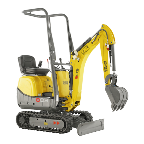
Wacker Neuson 803 Dualpower Operator's Manual (228 pages)
Track Excavator
Brand:
Wacker Neuson
| Category:
Excavators
| Size: 64 MB
Table of Contents
Table of Contents
3
Introduction
11
Information on this Operator's Manual
11
Machine Overview (up to Serial No. AI00966)
12
Machine Overview (from Serial No. AI00967)
13
Brief Description
14
Cooling System
14
Operating Hydraulics
14
Traveling Drive
14
Definition of the Term "Protective Structure
15
Explanation of Abbreviations
15
Rollbar
15
Mechanical Integrity
15
Responsibility for Machine Equipped with Protective Structures
15
Fields of Application, Attachments
16
Regulations
17
TOPS Rollbar (up to Serial No. AI00966)/ROPS
17
EC Declaration of Conformity
18
Type Labels and Component Numbers
19
Overview of Adhesive Labels
20
Noise Levels
21
Overview of Safety Labels
25
Safety Instructions
33
Safety Symbols Found in this Manual
33
Warranty
34
Disposal
34
Designated Use
34
Preparing to Use the Machine
35
Conditions for Use
35
Operator Training and Knowledge
35
Preparing for Use
35
Information on Visibility
36
Modifications and Spare Parts
36
Operator and Technician Qualifications and Basic Responsibilities
36
Operator/Owner Responsibility
36
Repair Person Qualifications
36
Safety Instructions Regarding Operation
37
Preparing for Use
37
Starting and Stopping
37
Carrying Passengers
38
Danger Zone Awareness
38
Job Site Awareness
38
Operating the Machine
38
Mechanical Integrity
39
Traveling
39
Operator Protection System
40
ROPS Rollbar
40
TOPS Rollbar (up to Serial No. AF01416)
40
Traveling Without ROPS Rollbar
40
Traveling Without TOPS Rollbar (up to Serial No. AF01416)
40
Shatter Protection (Option)
41
Work Range and Restricted Visibility
41
Applications with Lifting Gear
42
General Information
42
Operation with Lowered ROPS Rollbar
42
Operation with Lowered TOPS Rollbar (up to Serial No. AI00966)
42
Attachments
42
General Information Regarding Attachments
42
Installation Notes
43
Trailers
43
Hammer Operation
44
Safety Instructions
44
Working with a Hammer
44
Transport and Towing
45
Towing
45
Transporting
45
Safety Guidelines for Maintenance
45
General Maintenance Notes
45
Personal Safety Measures
46
Preparing for Maintenance and Repair Work
46
Performing Maintenance and Repairs
47
Special Hazards
47
Electrical Energy
47
Overhead Electric Lines
48
Underground Electric Lines
48
Gas, Dust, Steam, Smoke
49
Hydraulics
49
Msds
49
Noise
49
Tracks
49
Battery
51
Safety Guidelines While Using Internal Combustion Engines
51
Running the Engine
51
Dual Power Option
52
Fueling the Engine
52
Operation
55
Control Stand Overview (up to Serial No. AI00814)
56
Control Stand Overview (from Serial No. AI00815)
59
Display Elements (Overview)
60
Putting into Operation
61
Putting into Operation for the First Time
61
Running-In Period
61
Safety Instructions
61
Check Lists
62
Start-Up Checklist
62
Operation Checklist
63
Parking" Checklist
63
Machine Travel
64
Starter
64
Throttle
64
Indicator Lights and Warning Lights (Overview)
65
Traveling Signal (Option)
65
Procedure
67
Starting the Engine: General
67
Starting at Low Temperatures
68
Engine and Machine Warm-Up
68
When the Engine Has Started
68
Jump-Starting the Engine (Supply Battery)
69
Operating Temperature Range
70
Special Instructions for Traveling on Public Roads
70
Starting Machine Travel
70
Travel Levers
70
Travel Position
70
ISO/SAE Changeover (Option)
71
Hydraulic Brake
72
Stabilizer Blade as a Parking Brake
72
Machine Travel on Slopes
73
Gradient Angle
74
Lateral Angle of Inclination
75
Changing the Width of the Stabilizer Blade
76
Stabilizer Blade Operation
76
Telescopic Travel Gear
78
Upper Carriage Lock
79
Parking the Machine
80
Parking the Machine on Slopes
80
Light System
81
Power Outlet
81
Access to the Control Stand
82
Seat Adjustment
82
Telescopically Extended Travel Gear
83
Lowerable TOPS Rollbar (up to Serial No. AI00966) (Option)
84
Lowering the Rollbar
84
Raising the Rollbar
85
Lowerable ROPS Rollbar (up to Serial No. AI00966) (Option)
86
Lowering the Rollbar
86
Lowering the Rollbar
87
Raising the Rollbar
87
Lowerable ROPS Rollbar (from Serial No. AI00967) (Option)
88
Lowering the Rollbar
88
Raising the Rollbar
89
Seat Belt (Option)
91
Engine Cover
95
Battery Master Switch
96
Towing the Machine
97
Lifting the Machine
98
Loading and Transporting the Machine
100
Tying down the Machine
101
Shatter Protection (Option) (from Serial No. AI00967)
102
General Safety Instructions
104
Machine Operation
104
Control Lever Overview
106
Left-Hand Control Lever
106
Right-Hand Control Lever
106
Boom Swivel Controls
107
Boom Swivel Controls (up to Serial No. AI00975)
107
Boom Swivel Controls (from Serial No. AI00976)
108
Auxiliary Hydraulics
109
Auxiliary Hydraulics (up to Serial No. AI00975)
109
Auxiliary Hydraulics (from Serial No. AI00976)
110
Auxiliary Hydraulics (Double-Action Option) (up to Serial No. AI00975)
111
Auxiliary Hydraulics (Double-Action Option) (from Serial No. AI00976)
112
Emergency Lowering
114
Rotating the Upper Carriage
115
Upper Carriage Deceleration
115
Lock Lever
116
Lock Lever (from Serial No. AI00815)
116
Lock Lever (up to Serial No. AI00814)
116
Dual Power (Option)
117
Overview of Connections
118
Coupling
119
Checking the Hydraulic Oil Levels of the Power Unit and Excavator
121
Changeover from HPU to Diesel Operation
122
Changeover from Diesel to HPU Operation
123
Uncoupling
124
Charging the Excavator Battery
125
Charging the Battery with the Mains
127
Charging the Battery with the Power Unit
127
Dual-Power Operation with Rotating Beacon
128
Pressure Release on the Auxiliary Hydraulics
129
Re-Equipping Attachments
129
Releasing Pressure
129
Removing a Bucket
130
Specific Safety Instructions
130
Connections for Auxiliary Hydraulics
131
Installing a Bucket
131
Connections for Auxiliary Hydraulics (Stick Hose Routing Option)
132
Attachments
133
Inadmissible Work Procedures
133
Maintenance of Attachments
133
Working with the Standard Bucket
133
Excavator Work Position
134
Bucket Position When Digging
135
Excavating Trenches
135
Loading
135
Excavating Trenches Sideways
136
Grading
136
Grading
137
Stabilizer Blade at Rear
138
Working Alongside Trenches
138
Malfunctions
139
Engine Trouble
139
Maintenance
141
Fuel System
142
Specific Safety Instructions
142
Draining Fuel
143
Refueling
143
Stationary Fuel Pumps
143
Bleeding the Fuel System
144
Fuel Prefilter with Water Separator
145
Engine Lubrication System
146
Adding Engine Oil
147
Checking the Oil Level
147
Engine Cooling System
148
Specific Safety Instructions
148
Checking the Coolant Level/Adding Coolant
150
Cleaning the Radiator
151
Air Filter
152
Air Filter (up to Serial No. AI00875)
153
Replacing Air Filter Elements
153
Air Filter (from Serial No. AI00876)
154
Replacing Air Filter Elements
154
V-Belt
155
Checking V-Belt Tension
155
Retightening the V-Belt
155
Hydraulic System
156
Important Information on the Hydraulic System
156
Adding Hydraulic Oil
157
Checking the Hydraulic Oil Level
157
Important Information on the Use of Biodegradable Oil
158
Checking Hydraulic Pressure Lines
159
Overview of Lubrication Points
160
Parking the Machine
161
Swiveling Cylinder Lubrication Points
161
Lubricating the Live Ring (Ball Bearing)
162
Lubricating the Teeth of the Live Ring
163
Ball Sockets (ISO/SAE Changeover Option)
164
Tracks
165
Checking Track Tension
165
Tightening the Tracks
166
Traveling Drive
167
Electrical System
168
Servicing and Maintenance at Regular Intervals
168
Specific Safety Instructions
168
Alternator
169
Instructions Concerning Specific Components
169
Battery
170
General Maintenance
171
Cleaning
171
General Instructions for All Areas of the Machine
171
Control Stand
172
Engine Compartment
172
Exterior of the Machine
172
Pivots and Hinges
173
Threaded Fittings and Attachments
173
Preparatory Work before Taking out of Service
173
Maintenance if the Machine Is out of Service for a Longer Period of Time
174
Putting into Operation Again
174
Fluids and Lubricants
175
Oil Change and Filter Replacement (Hydraulics)
177
Maintenance Label
183
Explanation of Symbols on the Maintenance Label
183
Technical Data
185
Engine
185
Travel Gear and Swivel Unit
186
Stabilizer Blade
187
Operating Hydraulics
187
Connection Values of Dual Power Option
187
Electrical System
187
Fuses Behind the Right-Hand Trim
188
Relays Behind the Right-Hand Trim
188
Fuses and Relays with Dual Power Option
189
Noise Levels
190
Vibration
190
Weight
193
Coolant Compound Table
193
Dimensions Model 803 (up to Serial No. AI00966)
194
Dimensions Model 803 with Rollbar (from Serial No. AI00967)
195
Dimensions Model 803 Without Rollbar (from Serial No. AI00967)
196
Lift Capacity Tables 803
197
Safety Instructions - Lift Capacity Table
197
Table of Contents
202
Foreword
203
Safety Alerts
203
A Word to the User/Operator
204
One-Call First
204
Follow a Safety Program
205
Prepare for Safe Operation
208
Start Safely
212
Operate Safely
214
Load and Unload the Machine Safely
221
Shut down Safely
221
Perform Maintenance Safely
222
Final Word to the User
227
Advertisement
Wacker Neuson 803 Dualpower Service Manual (196 pages)
Track excavator
Brand:
Wacker Neuson
| Category:
Excavators
| Size: 9 MB
Table of Contents
Table of Contents
3
SHB 803 en – Edition 2.4 * 803S20Ivz.fm
8
Operation
10
Information on this Service Manual
10
Identification of Warnings and Dangers
11
Designated Use and Exemption from Liability
12
Labels
13
Machine Overview (up to Serial No. AI00966)
15
Machine Overview (from Serial No. AI00967)
16
Control Stand Overview (up to Serial No. AI00814)
17
Control Stand Overview (from Serial No. AI00815)
19
Display Elements (Overview)
20
Engine Compartment Overview (up to Serial No. AI00814)
21
Engine Compartment Overview (from Serial No. AI00815)
22
Technical Data Chassis
24
Engine
24
Fuel Injection Pump
26
Engine Capacities
26
Engine Tightening Torques
26
Hydraulic System
26
Auxiliary Hydraulics Oil Flow
27
Travel Gear and Swivel Unit
27
Stabilizer Blade
27
Screwable Hose Burst Valve
27
Electrical System
28
Fuses Behind the Right-Hand Trim
28
Relays Behind the Right-Hand Trim
29
Fuses and Relays with Dual Power Option
29
Noise Levels
30
Vibration
30
Coolant Compound Table
30
Model-Specific Tightening Torques
31
General Tightening Torques
31
Tightening Torques for Hydraulic Threaded Fittings (Dry Assembly)
31
Tightening Torques for High-Resistance Threaded Fittings
33
Dimensions Model 803 (up to Serial No. AI00966)
34
Dimensions Model 803 with ROPS Rollbar (from Serial No. AI00967)
35
Dimensions Model 803 Without ROPS Rollbar (from Serial No. AI00967)
36
Lift Capacity Table 803 RD
37
Kinematics
37
Maintenance
39
Fluids and Lubricants
40
Additional Oil Change and Filter Replacement (Hydraulic System)
41
Explanation of Symbols on the Maintenance Label
43
Maintenance Label (up to Serial Number AF02412)
43
Maintenance Label (from Serial Number AF02413)
45
Maintenance Plan (Overview)
50
Service Package
50
Introduction
50
Safety-Relevant Parts
50
Fuel System
51
Specific Safety Instructions
51
Refueling
51
Stationary Fuel Pumps
52
Diesel Fuel Specification
52
Bleeding the Fuel System
53
Fuel Prefilter with Water Separator
53
Replacing the Fuel Filter
55
Engine Lubrication System
56
Checking the Oil Level
56
Adding Engine Oil
57
Changing Engine Oil
58
Replacing the Engine-Oil Filter Cartridge
59
Cooling System
60
Specific Safety Instructions
60
Checking the Coolant Level/Adding Coolant
61
Draining Coolant
63
Air Filter (up to Serial No. AI00875)
64
Replacing Air Filter Elements
65
Air Filter (from Serial No. AI00876)
65
Replacing Air Filter Elements
66
V-Belt
68
Checking V-Belt Tension
68
Retensioning the V-Belt
69
Pressure Check
70
General
70
Pressure Check of Gear Pump P2
70
Pressure Check of Gear Pump P1
71
Hydraulic System
74
Specific Safety Instructions
74
Checking the Hydraulic Oil Level
75
Adding Hydraulic Oil
76
Changing Hydraulic Oil
77
Replacing the Filter Cartridge
77
Checking Hydraulic Pressure Lines
78
Tracks
79
Checking Track Tension
79
Setting the Tracks
80
Lubrication Points on Boom (up to Serial Number AI00966)
81
Lubrication Strip
82
Overview of Lubrication Points (from Serial No. AI00967)
83
Parking the Machine
84
Lubrication Points on the Stabilizer Blade and Stabilizer Blade Cylinder
84
Lubrication Points on Swiveling Console
85
Swiveling Cylinder Lubrication Points
85
Lubrication Points on Live Ring (Ball Bearing)
86
Lubrication Points of Live Ring Teeth
87
Ball Sockets (ISO/SAE Changeover Option)
88
Maintenance of Attachments
88
Electrical System
89
Specific Safety Instructions
89
Servicing and Maintenance at Regular Intervals
89
Instructions Concerning Specific Components
90
Alternator
90
Battery
91
General Maintenance
92
Cleaning
92
General Instructions for All Areas of the Machine
92
Control Stand
92
Exterior of the Machine
93
Engine Compartment
93
Threaded Fittings and Attachments
93
Pivots and Hinges
93
Preparatory Work before Taking out of Service
94
Maintenance if the Machine Is out of Service for a Longer Period of Time
94
Putting into Operation Again
94
Engine
98
Overview of Engine 3TNV70-VNS (Tier IV Final up to 2012)
98
Fuel System
99
Checking and Adjusting Valve Clearance
101
Tightening Order for Cylinder Head Bolts
102
Checking the Injection Nozzles
103
Pressure Check
103
Checking the Nozzle Jet
103
Injection Time
104
Checking and Adjusting Injection Time
104
Replacement of Fuel Injection Pump
105
Adjusting Engine Speed
106
Compression
106
Checking the Coolant Thermostat
106
Checking the Thermal Switch
107
Oil Pressure Switch
107
Checking the Coolant Circuit
108
Engine Trouble
109
Overview of Engine 3TNV74F-SNNS (Tier IV Final from 2012)
111
Fuel System
113
Cooling System
114
Altitude-Dependent Output Reduction
115
Checking and Adjusting Valve Clearance
116
Tightening Order for Cylinder Head Bolts
118
Order for Removing the Cylinder-Head Bolts
118
Order for Installing the Cylinder-Head Bolts
118
Checking the Injection Nozzles
119
Pressure Check
119
Checking the Nozzle Jet
120
Injection Time
120
Checking Injection Time
120
Setting Injection Time
122
Removing and Installing the Injection Pump
123
Removing the Injection Pump
123
Fitting the Fuel Injection Pump
124
Measuring and Adjusting the Engine Speed
126
Compression
126
Checking the Coolant Thermostat
127
Checking the Temperature Sensor
127
Oil Pressure Switch
128
Checking the Coolant Circuit
128
Cleaning the Cooling Water Channels
128
Coolant and Fuel Hoses
129
Crankcase Vent
129
Replacing the Glow Plugs
129
Engine Trouble
130
Hydraulic System
133
Hydraulic Pump PGP505B0050CA1H2NJ7J5C-505A00 (Tier IV Final up to 2012)
134
Pump Unit: Exploded View
135
Hydraulic Pump PGP505B0040CA1H2NJ7J5C-505A0040XB1J5B1B1 (Tier IV Final from 2012)
136
Pump Unit: Exploded View
137
Main Valve Block
138
Connections
138
Legend
139
Main Valve Block Diagram
140
Pressure Limiting Valves
141
Pump Assignment
142
Traveling Drive
143
Function
144
Swivel Unit
146
Swivel Unit
147
Swivel Joint
148
Sealing
148
Mechanical Control
149
Control Levers (up to Serial No. AI00814)
149
Drive Levers (up to Serial No. AI00814)
150
Control Levers (from Serial Number AI00815)
151
Drive Levers (from Serial Number AI00815)
152
Lock Lever (from Serial Number AI00815)
153
Troubleshooting in the Hydraulic System
154
Plastic Trims
154
Electrical System
161
Ohm's Law (Current, Voltage, Resistance); Power
162
Measuring Equipment, Measuring Methods
162
Cable Color Coding
163
Relays
163
Use, Mode of Function
163
Electrical System
164
Fuses Behind the Right-Hand Trim
164
Relays Behind the Right-Hand Trim
165
Fuses and Relays with Dual Power Option
165
Control Lever Push Button
166
Working Light
166
Dynamo
167
Rectifier
167
Starter
167
Options
186
Rollbar
186
TOPS Rollbar up to Serial Number AF01416
186
Lowerable ROPS Rollbar (from Serial No. AF01417 to Serial No. AI00966)
187
Raising/Lowering the Rollbar
187
Lowering and Raising the Rollbar
188
Lowerable ROPS Rollbar from Serial No. AI00967
188
Raising/Lowering the Rollbar
189
ISO/SAE Changeover (Option)
190
Traveling Signal (Option)
191
Telematic
192
Connections
192
Functional Check/Diode
192
Zero-Emission Dual Power Drive
193
Overview
193
Advertisement
Related Products
Wacker Neuson 803 dual power
Wacker Neuson 8003
Wacker Neuson 8003 2
Wacker Neuson 8009640011
Wacker Neuson RT 82 SC-2
Wacker Neuson 1000164553
Wacker Neuson 1404
Wacker Neuson 2503
Wacker Neuson 28Z3
Wacker Neuson 28Z3 VDS
Wacker Neuson Categories
Power Tool
Portable Generator
Construction Equipment
Water Pump
Excavators
More Wacker Neuson Manuals
Login
Sign In
OR
Sign in with Facebook
Sign in with Google
Upload manual
Upload from disk
Upload from URL