Sign In
Upload
Manuals
Brands
VWR Manuals
Accessories
symphony 5.3 A
User Manuals: VWR symphony 5.3 A Incubator Accessories
Manuals and User Guides for VWR symphony 5.3 A Incubator Accessories. We have
1
VWR symphony 5.3 A Incubator Accessories manual available for free PDF download: Operating Instructions Manual
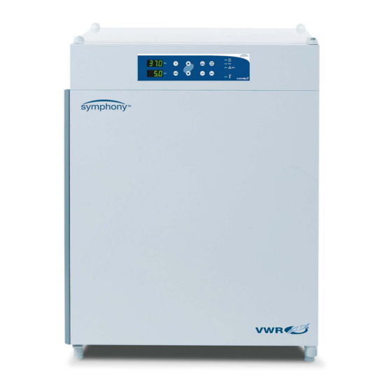
VWR symphony 5.3 A Operating Instructions Manual (68 pages)
CO2 Incubator
Brand:
VWR
| Category:
Accessories
| Size: 2 MB
Table of Contents
Table of Contents
3
Important Safety Informations
7
Instruction of the Operating Personnel
7
Applicability of the Instructions
7
Warranty
7
Explanation of Signs
8
Symbols and Signal Words Used in the Operating Instructions
8
Pictographs Used in the Operating Instructions
8
Signs on the Device
9
Overview Safety Informations
9
Intended Purpose of the Device
12
Correct Use
12
Incorrect Use
12
Standards and Directives
13
Delivery
14
Packaging
14
Components Standard Equipment
14
Acceptance Inspection
14
Installation of the Device
15
Ambient Conditions
15
Room Ventilation
15
Space Requirements
16
Transport
16
Fig.1: Device Dimensions
16
Fig.2: Lift Point
16
Stacking
17
Modifications
17
Fig.3: Stacking
17
Description of the Device
18
Views of Device
18
Fig.4: General Views of Device
19
Safety Devices
20
Work Space Atmosphere
20
Sensor System
21
Door Switch
21
Fig.5: Temperature Sensor
21
Fig.6: Door Switch
21
Switchbox with Supply Interface
22
Fig.7: Supply Interfaces
22
Work Space Components
23
Fig.8: Work Space Layout / Water Reservoir
23
Fig.9: Rear Panel Openings
24
C Decontamination Routine (Optional)
25
Start-Up
26
Preparing the Work Space
26
Installing the Shelf System
26
Fig.10: Support Rail Installation/Removal
26
Fig.11: Shelf Support/Sheet Insert Installation
27
Gas Connection
28
Fig.12: Gas Pressure Hose Installation
28
Power Supply Connection
29
RS 232 Interface Connection
29
Fig.13: Power Supply Connection
29
Fig.14: RS 232 Interface
29
Connecting the Alarm Contact
32
Fig.15: Example of a Connection Scheme
33
Operation
34
Preparing the Device
34
Starting Operation
34
Handling and Control
36
Power Switch
36
Operating Panel
36
Fig.16: Power Switch / Operating Panel
37
Control Self-Test
38
Setting the Nominal Temperature Value
39
Setting the CO Nominal Value
39
Activating the Auto-Start Routine
40
Reading Failure Codes
41
Resetting the Thermal Protection
45
Shut-Down
46
Shutting the Device down
46
Turn Device off Using the Power Switch
46
Cleaning and Disinfection
47
Decontamination Procedures
47
Wipe/Spray Disinfection
47
Fig.17: Removing Blower Wheel and Cover
49
C Decontamination Routine (Optional)
50
C Decontamination Routine Procedure
51
Fig.18: 90 °C Decontamination Routine Procedure
51
Activating the 90 °C Decontamination Routine
52
Cancelling the 90 °C Decontamination Routine
52
Maintenance
53
Inspections and Checks
53
Service Intervals
53
Preparing the Temperature Calibration
53
Fig.19: Temperature Calibration
54
Temperature Calibration Procedure
55
Preparing the CO Calibration
56
Fig.20: CO 2 Calibration
56
CO Calibration Procedure
57
Replacing the Sterile Filters
58
Replacing the Device Fuses
58
Fig.21: Sterile Filter Replacement
58
Fig.22: Device Fuse Replacement
58
Replacing the Door Seal
59
Fig.23: Door Seal Replacement
59
Parts and Accessories
60
Lists of Parts and Accessories
60
Technical Data
61
Fig.24: CO 2 Consumption
63
Advertisement
Advertisement
Related Products
VWR 531-1368
VWR 531-1382
VWR VisiScope 534 Series
VWR 5000 Advanced
VWR 521-1893
VWR 521-1895
VWR Avantor 528 Eco Premium
VWR 5607
VWR 5704
VWR avantor 521-3500 Mega Star 600
VWR Categories
Laboratory Equipment
Measuring Instruments
Microscope
Thermometer
Accessories
More VWR Manuals
Login
Sign In
OR
Sign in with Facebook
Sign in with Google
Upload manual
Upload from disk
Upload from URL