Sign In
Upload
Manuals
Brands
VIA Technologies Manuals
Motherboard
EPIA-M910
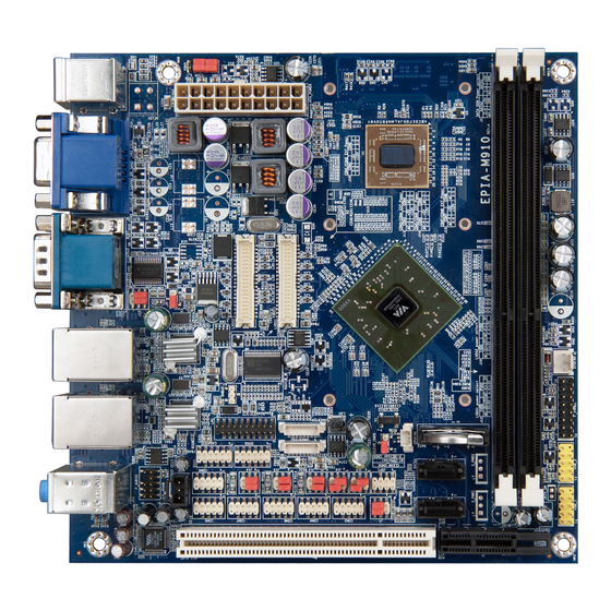
VIA Technologies EPIA-M910 Manuals
Manuals and User Guides for VIA Technologies EPIA-M910. We have
2
VIA Technologies EPIA-M910 manuals available for free PDF download: User Manual
VIA Technologies EPIA-M910 User Manual (107 pages)
Highly-integrated Mini-ITX board with rich feature set and multiple expansion options
Brand:
VIA Technologies
| Category:
Motherboard
| Size: 8 MB
Table of Contents
Table of Contents
5
1 Product Overview
12
Key Features and Benefits
12
VIA Nano ® X2 E-Series/Eden ® X2/Quadcore E-Series CPU
12
VIA VX900 MSP Chipset
12
Modular Expansion Options
13
Product Specifications
14
Layout Diagram
16
Figure 1: Layout Diagram of the VIA EPIA-M910 (Top View)
16
Table 1: Layout Diagram Description Table of the VIA EPIA-M910
17
Product Dimensions
18
Figure 2: Mounting Holes and Dimensions of the VIA EPIA-M910
18
Figure 3: External I/O Port Dimensions of the VIA EPIA-M910
18
Height Distribution
19
Figure 4: Height Distribution
19
Figure 5: Height Distribution of the VIA EPIA-M910 (for EPIA-M910-10E & EPIA-M910-10PE)
20
2 I/O Interface
21
External I/O Ports
21
Figure 6: Back Panel I/O Ports
21
Table 2: Layout Diagram Description Table of the Back Panel I/O Ports
21
Figure 7: PS/2 Port Diagram
22
Figure 8: VGA Port Diagram
22
PS/2 Port
22
Table 3: PS/2 Port Pinouts
22
Table 4: VGA Port Pinouts
22
VGA Port
22
COM Port
23
Figure 10: Gigabit Ethernet Port Diagram
23
Figure 9: COM Port Diagram
23
Gigabit Ethernet Port
23
Table 5: COM Port Pinouts
23
Table 6: Gigabit Ethernet Port Pinouts
23
Table 7: Gigabit Ethernet LED Color Definition
23
Audio Jack
24
Figure 11: Audio Jack Receptacle Stack Diagram
24
Figure 12: HDMI ® Port Diagram
24
HDMI ® Port
24
Table 8: Audio Jack Receptacle Pinouts
24
Table 9: HDMI ® Port Pinouts
24
Figure 13: USB 2.0 Port Diagram
25
Table 10: USB 2.0 Port Pinouts
25
USB 2.0 Port
25
Onboard I/O
26
ATX Power Connector
26
Figure 14: ATX Power Connector Diagram
26
Table 11: ATX Power Connector Pinouts
26
LVDS Panel Connectors
27
Figure 15: LVDS Panel Connectors Diagram
27
Table 12: LVDS1 Panel Connector Pinouts
27
Table 13: LVDS2 Panel Connector Pinouts (Dual-Channel)
28
Table 14: LVDS2 Panel Connector Pinouts (Single-Channel)
28
LVDS Inverter Connectors
29
Figure 16: LVDS Inverter Connectors Diagram
29
Table 15: LVDS Inverter Connectors Pinouts
29
Digital I/O Pin Headers
30
Figure 17: Digital I/O Pin Headers Diagram
30
Table 16: Digital I/O Pin Headers Pinouts
30
DC-In Power Connector
31
Figure 18: DC-In Power Connector Diagram
31
Table 17: DC-In Power Connector Pinouts
31
SATA Power Connectors
32
Figure 19: SATA Power Connectors Diagram
32
Table 18: SATA Power Connectors Pinouts
32
CMOS Battery Slot
33
Figure 20: CMOS Battery Slot Diagram
33
Table 19: CMOS Battery Slot Pinouts
33
Front Panel Pin Header
34
Figure 21: Front Panel Pin Header Diagram
34
Table 20: Front Panel Pin Header Pinouts
34
Smbus Pin Header
35
Figure 22: Smbus Pin Header Diagram
35
Table 21: Smbus Pin Header Pinouts
35
CPU and System Fan Connectors
36
Figure 23: CPU and System Fan Connectors Diagram
36
Table 22: CPU and System Fan Connectors Pinouts
36
SATA Connectors
37
Table 23: SATA Connectors Pinouts
37
USB 2.0 Pin Headers
38
Figure 24: USB 2.0 Pin Headers Diagram
38
Table 24: USB 2.0 Pin Headers Pinouts
38
COM Pin Headers
39
Figure 25: COM Pin Headers Diagram
39
Table 25: COM Pin Headers Pinouts
39
PS/2 Keyboard and Mouse Pin Header
40
Figure 26: PS/2 Keyboard and Mouse Pin Header Diagram
40
Table 26: PS/2 Keyboard and Mouse Pin Header Pinouts
40
Front Audio Pin Header
41
Figure 27: Front Audio Pin Header Diagram
41
Table 27: Front Audio Pin Header Pinouts
41
S/PDIF-Out Connector
42
Figure 28: S/PDIF-Out Connector Diagram
42
Table 28: S/PDIF-Out Connector Pinouts
42
SPI Pin Header
43
Figure 29: SPI Pin Header Diagram
43
Table 29: SPI Pin Header Pinouts
43
LPC Pin Header
44
Figure 30: LPC Pin Header Diagram
44
Table 30: LPC Pin Header Pinouts
44
3 Jumpers
45
Figure 31: Jumper Settings Example
45
Clear CMOS Jumper
46
Figure 32: Clear CMOS Jumper Diagram
46
Table 31: Clear CMOS Jumper Settings
46
SATA DOM Power Jumper
47
Figure 33: SATA DOM Power Jumper Diagram
47
Table 32: SATA DOM Power Jumper Settings
47
COM1 and COM2 Voltage Jumper
48
Figure 34: COM1 and COM2 Voltage Jumper Diagram
48
Table 33: COM1 and COM2 Voltage Jumper Settings
48
COM3 and COM4 Voltage Jumper
49
Figure 35: COM3 and COM4 Voltage Jumper Diagram
49
Table 34: COM3 and COM4 Voltage Jumper Settings
49
COM5 and COM6 Voltage Jumper
50
Figure 36: COM5 and COM6 Voltage Jumper Diagram
50
Table 35: COM5 and COM6 Voltage Jumper Settings
50
COM7 and COM8 Voltage Jumper
51
Figure 37: COM7 and COM8 Voltage Jumper Diagram
51
Table 36: COM7 and COM8 Voltage Jumper Settings
51
LVDS Power Jumpers
52
Figure 38: LVDS Power Jumpers Diagram
52
Table 37: LVDS Power Jumpers Settings
52
AT/ATX Mode Jumper
53
Figure 39: AT/ATX Mode Jumper Diagram
53
Table 38: AT/ATX Mode Jumper Settings
53
Jatx_On Mode Jumper
54
Figure 40: Jatx_On Mode Jumper Diagram
54
Table 39: Jatx_On Mode Jumper Settings
54
4 Expansion Slots
55
DDR3 Memory Slots
55
Installing a Memory Module
55
Figure 41: DDR3 Memory Slots Diagram
55
Figure 42: Unlocking the Memory DIMM Slot
55
Figure 43: Inserting the Memory Module
56
Figure 44: Locking the Memory Module
56
Removing a Memory Module
57
Figure 45: Removing the Memory Module
57
PCI Slot
58
Figure 46: PCI Slot Diagram
58
Figure 47: PCI Express Slot Diagram
59
PCI Express Slot
59
5 Hardware Installation
60
Installing into a Chassis
60
Suggested Minimum Chassis Dimensions
60
Figure 48: Suggested Minimum Chassis Dimensions
60
Suggested Minimum Chassis Height
61
Suggested Keepout Areas
61
Figure 49: Suggested Minimum Internal Chassis Ceiling Height
61
Figure 50: Suggested Keepout Areas
61
6 BIOS Setup Utility
62
Entering the BIOS Setup Utility
62
Control Keys
62
Navigating the BIOS Menus
62
Getting Help
62
Main Menu
63
Amibios
63
Processor
63
System Memory
63
System Time
63
System Date
63
Figure 51: Illustration of the Main Menu Screen
63
Advanced Settings
64
Figure 52: Illustration of the Advanced Settings Screen
64
CPU Configuration
65
Pmon
65
Figure 53: Illustration of the CPU Configuration Screen
65
Figure 54: Illustration of SATA Configuration Screen
65
IDE Configuration
65
Superio Configuration
66
Figure 55: Illustration of Superio Configuration Screen
66
Serial Ports 1 to 8 Address
66
Table 40: Serial Port Addresses and Irqs
66
Hardware Health Configuration
67
Cpu/System Fan Mode Setting
67
Figure 56: Illustration of Hardware Health Configuration Screen
67
ACPI Settings
68
ACPI Version Features
68
Figure 57: Illustration of ACPI Configuration Screen
68
Suspend Mode
68
USB S4 Wakeup
68
APM Settings
69
Figure 58: Illustration of APM Configuration Screen
69
Power Button Mode
69
Restore on Ac/Power Loss
69
PCI Lan S5 Wakeup
70
Resume on PS/2 KBC
70
Resume on PS/2 Mouse
70
Resume on RTC Alarm
70
Wake-Up Key
70
Wake-Up Password
70
RTC Alarm Date (Days)
71
System Time
71
Spread Spectrum Configuration
72
CPU Spread Spectrum Setting
72
Figure 59: Illustration of Spread Spectrum Configuration Screen
72
USB Configuration
73
Figure 60: Illustration of USB Configuration Screen
73
Legacy USB Support
73
USB 2.0 Controller Mode
73
CRB Configuration
74
Figure 61: Illustration of CRB Configuration Screen
74
LAN Option ROM
74
VT6130 LAN Control
74
Boot Settings
75
Boot Settings Configuration
75
Figure 62: Illustration of Boot Settings Screen
75
Figure 63: Illustration of Boot Settings Configuration Screen
75
Bootup Num-Lock
76
Hit 'DEL' Message Display
76
Quick Boot
76
Quiet Boot
76
Wait for 'F1' if Error
76
Security Settings
77
Change Supervisor Password
77
Password Check
77
Figure 64: Illustration of Security Settings Screen
77
Advanced Chipset Settings
78
North Bridge VIA VX900 Configuration
78
Figure 65: Illustration of Advanced Chipset Settings Screen
78
Figure 66: Illustration of North Bridge VIA VX900 Configuration Screen
78
DRAM Clock
79
DRAM Clock/Timing Configuration
79
Figure 67: Illustration of DRAM Frequency/Timing Configuration Screen
79
CPU Direct Access Frame Buffer
80
Figure 68: Illustration of Onchip VGA Configuration Screen
80
Onchip VGA Configuration
80
Panel Type
80
Select Display Device 1 and 2
80
VGA Share Memory (Frame Buffer)
80
LCD/LCD2 Backlight Control
81
South Bridge VIA VX900 Configuration
82
Eup/Erp Lot6 Support
82
Figure 69: Illustration of South Bridge VIA VX900 Configuration Screen
82
Onchip HDAC Device
82
WATCHDOG Timer Enable
82
Exit Options
83
Save Changes and Exit
83
Discard Changes and Exit
83
Discard Changes
83
Load Optimal Defaults
83
Figure 70: Illustration of Exit Options Screen
83
7 Software and Technical Support
84
Microsoft and Linux Support
84
Driver Installation
84
Technical Supports and Assistance
84
Appendix A. Installing Wireless Accessories
85
Installing the VIA VNT9271 Wi-Fi USB Dongle
85
Figure 71: Inserting the VIA VNT9271 USB Wi-Fi Dongle
85
Installing the VIA EMIO-1533 USB Wi-Fi Module
86
Figure 72: Installing VIA EMIO-1533 Module to the Chassis
86
Figure 73: Connecting the USB Wi-Fi Cable (VIA EMIO-1533)
86
Figure 74: Installing Wi-Fi Antenna Cable (VIA EMIO-1533)
87
Figure 75: Connecting Wi-Fi Antenna Cable to the Micro-RF Connector (VIA EMIO-1533)
87
Installing the VIA EMIO-5531 USB Wi-Fi & Bluetooth Module
88
Figure 76: Installing VIA EMIO-5531 Module to the Chassis
88
Figure 77: Connecting the USB Wi-Fi Cable (VIA EMIO-5531)
88
Figure 78: Installing Wi-Fi Antenna Cable (VIA EMIO-5531)
89
Figure 79: Connecting Wi-Fi Antenna Cable to the Micro-RF Connector (VIA EMIO-5531)
89
Appendix B. Power Consumption Report
90
Epia-M910-16
90
Playing DVD - Power DVD 5.0
90
Playing MP3-Media Player
90
Running Network Application
91
Idle
91
RUN Burn-In Test
91
Eup/Erp Enable S3
92
Eup/Erp Enable S5
93
Epia-M910-16P
94
Playing DVD - Power DVD 5.0
94
Playing MP3 - Media Player
94
Running Network Application
94
Idle
94
RUN Burn-In Test
95
Eup/Erp Enable S3
95
Eup/Erp Enable S5
95
Epia-M910-10E
96
Playing DVD - Power DVD 5.0
96
Playing MP3 - Media Player
96
Running Network Application
96
Idle
97
RUN Burn-In Test
97
Eup/Erp Enable S3
98
Eup/Erp Enable Power off
98
Epia-M910-10Pe
99
Playing DVD - Power DVD 5.0
99
Playing MP3 - Media Player
99
Running Network Application
99
Idle
99
RUN Burn-In Test
100
Eup/Erp Enable S3
100
Eup/Erp Enable S5
100
Epia-M910-12Pq
101
Playing DVD - Power DVD 5.0
101
Playing MP3 - Media Player
101
Running Network Application
101
Idle
101
RUN Burn-In Test
102
Eup/Erp Enable S3
102
Eup/Erp Enable S5
102
Epia-M910-12Q
103
Playing DVD - Power DVD 5.0
103
Playing MP3 - Media Player
103
Running Network Application
103
Idle
104
RUN Burn-In Test
104
Eup/Erp Enable S3
105
Eup/Erp Enable S5
105
Appendix C. Mating Connector Vendor List
106
Table 41: VIA EPIA-M910 Mating Connector Vendors List
106
Advertisement
VIA Technologies EPIA-M910 User Manual (136 pages)
Mini-ITX embedded board
Brand:
VIA Technologies
| Category:
Motherboard
| Size: 5 MB
Table of Contents
Regulatory Compliance
2
Safety Precautions
3
Table of Contents
5
1 Product Overview Product Overview
15
Key Features and Benefits
16
VIA Nano X2 / Eden X2 Processor/Via Quadcore
16
VIA VX900 MSP Chipset
17
Modular Expansion Options
17
Product Specifications
18
Layout Diagram
21
Product Dimensions
23
Height Distribution
25
2 I/O Interface
27
External I/O Ports
27
PS/2 Port
28
VGA Port
29
COM Port
30
RJ45 LAN Port: Gigabit Ethernet
31
Audio Ports
32
HDMI Port
33
USB 2.0 Port
34
Onboard Connectors
35
ATX Power Connector
35
LVDS Panel Connectors
36
LVDS Inverter Connector
38
Digital I/O Pin Headers
39
DC-In Power Connector
40
SATA Power Connector
41
CMOS Battery Slot
42
Front Panel Pin Header
43
Smbus Pin Header
44
CPU and System Fan Connectors
45
SATA Connectors
46
USB 2.0 Pin Headers
47
COM Pin Header for COM3~COM8
48
PS/2 Keyboard and Mouse Pin Header
49
Front Audio Pin Header
50
SPDIF Connector
51
SPI Pin Header
52
LPC Pin Header
53
3 Jumpers
54
Clear CMOS Jumper
54
SATA DOM Power Select Jumper
56
COM1 and COM2 Voltage Select Jumper
57
COM3 and COM4 Voltage Select Jumper
58
COM5 and COM6 Voltage Select Jumper
59
COM7 and COM8 Voltage Select Jumper
60
LVDS Jumper Settings
61
AT/ATX Mode Jumper (1-2: ATX/2-3:AT)
62
Jatx_On Mode Jumper
63
4 Expansion Slots
65
DDR3 Memory Slots
65
Installing a Memory Module
66
Removing a Memory Module
68
PCI Slot
69
PCI Express Slot
70
5 Hardware Installation Hardware Installation
71
Installing into a Chassis
71
Suggested Minimum Chassis Dimensions
71
Suggested Minimum Chassis Height
72
Suggested Keepout Areas
73
6 BIOS Setup Utility
75
Entering the BIOS Setup Utility
75
Control Keys
75
Navigating the BIOS Menus
76
Getting Help
76
Main Menu
77
Amibios
77
Processor
77
System Memory
77
System Time
78
System Date
78
Advanced Settings
79
CPU Configuration
80
IDE Configuration
81
Superio Configuration
82
Hardware Health Configuration
83
ACPI Settings
84
Acpi Version Features
85
APM Settings
86
Resume on Rtc Alarm
89
Spread Spectrum Configuration
90
USB Configuration
91
CRB Configuration
93
Boot Settings
94
Boot Settings Configuration
95
Security Settings
97
Advanced Chipset Settings
99
North Bridge VIA VX900 Configuration
100
South Bridge VIA VX900 Configuration
104
Exit Options
105
Save Changes and Exit
105
Discard Changes and Exit
105
Discard Changes
105
Load Optimal Defaults
106
7 Driver Installation
107
Microsoft Driver Support
107
Linux Driver Support
107
Appendix A. Power Consumption Report Appendix A. Power Consumption Report
109
Epia-M910-16
109
Playing DVD - Power DVD 5.0
109
A.1.1. Playing DVD – Power DVD
109
Playing MP3-Media Player
110
Running Network Application
110
Idle
111
RUN Burn-In Test
111
Eup/Erp Enable S3
113
Eup/Erp Enable S5
113
Epia-M910-16P
114
Playing DVD - Power DVD 5.0
114
Playing MP3 - Media Player
114
A.2.1. Playing DVD – Power DVD
114
A.2.2. Playing Mp3 – Media Player
114
Running Network Application
115
Idle
115
RUN Burn-In Test
115
Eup/Erp Enable S3
116
Eup/Erp Enable S5
117
Epia-M910-10E
118
Playing DVD - Power DVD 5.0
118
A.3.1. Playing DVD – Power DVD
118
Playing MP3 - Media Player
119
A.3.2. Playing Mp3 – Media Player
119
Running Network Application
119
Idle
120
RUN Burn-In Test
120
Eup/Erp Enable S3
122
Eup/Erp Enable Power off
122
Epia-M910-10Pe
123
Playing DVD - Power DVD 5.0
123
Playing MP3 - Media Player
123
A.4.1. Playing DVD – Power DVD
123
A.4.2. Playing Mp3 – Media Player
123
Running Network Application
124
Idle
124
RUN Burn-In Test
124
Eup/Erp Enable S3
125
Eup/Erp Enable S5
126
Epia-M910-12Pq
127
Playing DVD - Power DVD 5.0
127
Playing MP3 - Media Player
127
A.5.1. Playing DVD – Power DVD
127
A.5.2. Playing Mp3 – Media Player
127
Running Network Application
128
Idle
128
RUN Burn-In Test
128
Eup/Erp Enable S3
129
Eup/Erp Enable S5
130
Epia-M910-12Q
131
Playing DVD - Power DVD 5.0
131
A.6.1. Playing DVD – Power DVD
131
Playing MP3 - Media Player
132
A.6.2. Playing Mp3 – Media Player
132
Running Network Application
132
Idle
133
RUN Burn-In Test
133
Eup/Erp Enable S3
135
Eup/Erp Enable S5
135
Advertisement
Related Products
VIA Technologies EPIA-M900
VIA Technologies EPIA-M920
VIA Technologies EPIA-M920-10E
VIA Technologies EPIA-M920-12Q
VIA Technologies EPIA-M930
VIA Technologies EPIAML8000A - C3 DDR266 6CH Dolby 5.1
VIA Technologies EPIA-M10000G - VIA Motherboard - Mini ITX
VIA Technologies EPIA MII-Series Mini-ITX
VIA Technologies EPIA-M Mini-ITX
VIA Technologies EPIA-M800
VIA Technologies Categories
Motherboard
Computer Hardware
Desktop
Control Unit
Industrial PC
More VIA Technologies Manuals
Login
Sign In
OR
Sign in with Facebook
Sign in with Google
Upload manual
Upload from disk
Upload from URL