Sign In
Upload
Manuals
Brands
Vaisala Manuals
Weather Station
AWS310-SITE
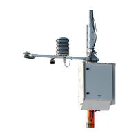
Vaisala AWS310-SITE Monitoring System Manuals
Manuals and User Guides for Vaisala AWS310-SITE Monitoring System. We have
4
Vaisala AWS310-SITE Monitoring System manuals available for free PDF download: Installation Manual, Configuration And Maintenance Manual, Integration Manual, Technical Note
Vaisala AWS310-SITE Installation Manual (274 pages)
Brand:
Vaisala
| Category:
Weather Station
| Size: 26.89 MB
Table of Contents
Table of Contents
3
About this Document
11
Version Information
11
Related Manuals
11
Table 1 Document Versions
11
Table 2 AWS310 and AWS310-SITE Manuals
11
Table 3 Related Manuals
11
Documentation Conventions
13
Trademarks
13
Product Overview
15
Product Nomenclature
16
Table 4 System Components
16
Safety
17
Table 5 Sensors
17
ESD Protection
20
Regulatory Compliances
21
Installation Preparation
23
Preparing for Installation
23
Selecting Location
23
Placing System
23
Placing Mast
23
Placing Antennas
24
Placing Sensors
24
Figure 2 Recommended Mast Location in Open Area
24
Placing Weather Station
26
Figure 3 Recommended Site Layout with Distances
27
Preparing Site
28
Laying Foundations
28
Designing Concrete Foundation for Rain Gauges
28
Figure 4 RG13(H) Round Foundation (DRW231218)
29
Figure 5 RG13(H) Square Foundation (DRW231219)
30
Figure 6 DRW231233 Round Concrete Reinforcing FS11, FD12, CL31
32
Power Supply and Communication Lines
33
Unpacking
33
Necessary Tools and Equipment
33
Overview of Installation
35
Mast Installation
37
Overview of Mast Installation
37
Component Placement on Pole Mast
37
Figure 7 Dimensions for Sensor Support Arm, BOX652, Winch, and
38
Grounding and Lightning Protection
39
Grounding Enclosure
40
Wind Sensor or Weather Transmitter Installation
45
Overview of Wind Sensor or Weather Transmitter Installation
45
Installing WMT52
45
Figure 8 WMT52 Installation on Pole Mast
46
Placing WMT52
47
Connecting WMT52 Cable
47
Mounting WMT52
48
Aligning WMT52
50
Installing WMT700
51
Placing WMT700
52
Unpacking and Handling WMT700
53
Figure 9 Removing WMT700 Bottom Transportation Damper
53
Connecting WMT700 Cable
54
Figure 10 Handling WMT700
54
Mounting WMT700 with WMT700FIX60-RST
57
Figure 11 WMT700 Installation Accessories
58
Mounting Dual WMT700
60
Figure 12 Mounting 2 WMT700 Sensors on Top of Mast
61
Aligning WMT700
64
Figure 13 WMT700 North Arrow
64
WMT700 Cable Wiring
65
Table 6 Pin-Out for Cable 228260
65
Installing WA15
66
Figure 14 Vaisala Serial Wind Transmitter WAC155
67
Connecting Wind Transmitter Cable
68
Mounting Wind Sensors on Cross Arm
69
Mounting Wind Set on Mast
70
Aligning Wind Set
71
Figure 15 WA15 Installed on Top of Mast
71
Installing WXT520
72
Connecting WXT520 Cable
73
Aligning WXT520
74
Configuring Wind Direction Offset
75
Obstruction Light Installation
77
Overview of Obstruction Light Installation
77
Installing QOL111
77
Figure 16 Installing and Positioning QOL111
78
Communication Device Installation
81
Overview of Communication Device Installation
81
Installing UHF Antenna
81
Figure 17 UHF Antenna Location on Mast
82
Installing 2G/3G Antenna
84
Figure 18 2G/3G Antenna Installation on Mast
84
Solar Panel Installation
87
Overview of Solar Panel Installation
87
Installing Solar Panel
87
Figure 19 Solar Panel Installation Accessories
88
Adjusting Solar Panel Tilt Angle
89
Figure 20 APPK-SET106
89
Table 7 Recommended Tilt Angle for Solar Panel
89
Figure 21 Map of Latitudes
90
Sensor Support Arm Installation
93
Overview of Sensor Support Arm Installation
93
Mounting Full-Length Sensor Support Arm on DKP200
94
Figure 22 DKP12SUP2 Installation Accessories
94
Figure 23 DKP060SUP2 Installation Accessories
95
Figure 24 DKP060SUP2 Installed
95
Mounting Half-Length Sensor Support Arm on DKP200
96
Figure 25 DKP12SUP1 Installation Accessories
96
Figure 26 DKP060SUP1 Installation Accessories
97
Figure 27 DKP12SUP1 Installed
97
Mounting Sensor Support Arm on DKE110
98
Figure 28 DKP060SUP1 Installed
98
Figure 29 DKE110FSUP1 Installation Accessories
99
Mounting Full-Length Sensor Support Arm on DKE200
101
Figure 30 DKE200SUP2 Installation Accessories
102
Mounting Half-Length Sensor Support Arm on DKE200
104
Figure 31 Full-Length Sensor Support Arm Installed on DKE200
104
Figure 32 DKE200SUP1 Installation Accessories
105
Figure 33 Half-Length Sensor Support Arm Installed on DKE200
107
Sensor Installation to Sensor Support Arm
109
Installing HMP155
109
Mounting HMP155 Inside Radiation Shield DTR503A
109
Figure 34 HMP155 and DTR503A Installation Accessories
111
Mounting HMP155 Inside Radiation Shield DTR13
114
Figure 35 HMP155 and DTR13 Installation Accessories
115
Mounting HMP155 to Stevenson Screen
119
Figure 36 HMP155 with T-Probe in Stevenson Screen
119
Installing HMP110
120
Figure 37 HMP110 Probe with Radiation Shield
120
Installing SR50A
121
Figure 38 SR50A Beam Angle Clearance
122
Figure 39 SR50A Installation Accessories
123
Installing CMP
126
Figure 40 Installing Pyranometer CMP6
127
Installing SP Lite2
128
Figure 41 SP Lite2 Installation Accessories
129
Installing FS11
133
Installing PWD
133
Placing PWD
133
Mounting PWD on Sensor Support Arm
135
Figure 42 PWD Installation Accessories
135
Enclosure Installation
139
Overview of Enclosure Installation
139
Installing BOX652
139
Figure 43 BOX652 and Components
141
Installing BOX652 on Pole Mast
142
Figure 44 BOX652 Dimensions
142
Figure 45 BOX652 and APPK-SET Mounting Kit
143
Figure 46 APPK-SET106 Mounting Clamp
144
Figure 47 BOX652 Mounting Frame for APPK-SET Mounting Kit (Front and Back)
144
Installing BOX652 on Frangible Lattice Mast
152
Figure 48 Enclosure Installed on Frangible Lattice Mast
156
Installing BOX652 with Mounting Frame on Wall or Back Panel
157
Figure 49 Installing BOX652 on Wall with Mounting Frame
157
Figure 50 BOX652 Wall or Back Panel Installation Accessories
158
Figure 51 BOX652 Mounting Frame for Wall or Back Panel Installation (Front)
159
Installing BOX652 Without Mounting Frame on Wall or Back Panel
164
Figure 52 BOX652 Enclosure Installed on Wall
165
Finalizing BOX652 Installation
166
Figure 53 Installing Radiation Shield on BOX652 Installed on Pole Mast
167
Figure 54 Installing Radiation Shield on BOX652 Installed on Wall
168
Figure 55 Installing Radiation Shield on BOX652 Installed on Frangible Lattice Mast
169
TERMBOX Installation
171
Overview of TERMBOX Installation
171
Placing TERMBOX
171
Installing TERMBOX on Pole Mast
172
Figure 56 TERMBOX Installed in Pole Mast
173
Installing TERMBOX on Frangible Lattice Mast
174
Grounding TERMBOX
175
Figure 57 TERMBOX Installed on Lattice Mast
175
Grounding TERMBOX Signal Cable
176
Figure 58 TERMBOX Grounding
176
Figure 59 Cable Glands
177
Installing CL31
179
Subsurface Sensor Installation
181
Overview of Subsurface Sensor Installation
181
Installing QMT107
181
Installing QMT110
185
Figure 60 Removing Plastic Cover from EC-5
187
Installing EC-5
188
Installing EC-5 Close to Ground Surface
188
Installing EC-5 Deep in Ground
188
Installing DRS511
189
Necessary Equipment for Embedded Sensor Installation
189
Table 8 Equipment Needed for Embedded Sensor Installation
189
Table 9 Equipment for Cold Filling Material
190
Table 10 Examples of Slot Filling Material
190
Cable Ducting for Embedded Sensors
191
Table 11 Equipment for Hot Filling Material
191
Cutting Slot for DRS511 Installation
192
Figure 61 DRS511 Slot Dimensions
192
Installing DRS511 Using Cold Filling Material
194
Figure 62 DRS511 Positioning (Cold Filling Material)
194
Installing DRS511 Using Hot Filling Material
196
Figure 63 DRS511 Positioning (Hot Filling Material)
196
Precipitation Sensor Installation
199
Installing RGSTAND
199
Figure 64 RGSTAND Dimensions
200
Installing RG13(H)
201
Figure 65 RG13(H) Installation Accessories
203
Installing QMR102
207
Installing OTT Pluvio L
209
Unpacking OTT Pluvio L
210
Mounting OTT Pluvio L
210
Electrical Installation
213
Overview of Electrical Installation
213
Location of Components in Enclosure
215
Figure 66 Location of Components in Enclosure for AWS310 (with Rubber Flange)
215
Figure 67 Location of Components in Enclosure for AWS310-SITE (with Steel Flange)
217
Preparing Modem
218
Inserting External Memory Card
219
Connecting Sensor and Device Cables
220
Standard Cable Lengths
220
Table 12 QML Data Logger LED Blinking Sequences
220
Table 13 Standard Cable Lengths
220
Routing Cables
221
Connecting Sensor Cables (Rubber Flange)
221
Figure 68 Enclosure Bottom View, Rubber Flange
222
Figure 69 Rubber Flange
223
Connecting Sensor Cables (Steel Flange)
224
Figure 70 Enclosure Bottom View, Steel Flange
225
Figure 71 Stainless Steel Flange
225
Connecting Communication Cables
226
TERMBOX Connections
227
Figure 72 Front View of AC Power Connections
227
Connecting TERMBOX AC (Mains) Cable
228
Connecting Power Cables
228
Connecting AC (Mains) Power
228
Mounting and Connecting 26 Ah Backup Battery
231
Connecting Solar Panel Cables
234
Powering up
234
Finalizing and Checking Installation
235
Sensor Transportation
237
Disassembling Sensors for Transportation
237
Appendix A: Wiring Diagrams
239
QML Data Logger Connector Block
239
Table 14 Analog Measurement Channels
239
Figure 73 QML Data Logger Connector Blocks, Analog Measurement Channels CH0 - CH3
240
Figure 74 QML Data Logger Connector Blocks, Analog Measurement Channels CH4 - CH7
241
Figure 75 QML Data Logger Connector Blocks, Analog Measurement Channels CHA and CHB
242
Table 15 Power Channels in QML201C
242
Figure 76 QML Data Logger Connector Blocks, Power Connector in QML201C
243
TERMBOX Wiring Diagrams
244
Figure 77 TERMBOX-1200 General Wiring Diagram
244
AWS310 System Basic Wiring Diagrams
245
Figure 78 TERMBOX-1212 General Wiring Diagram
245
AWS310 Power Connections
246
Figure 79 AWS310, Power Connections
246
AWS310 Data Signals
247
Figure 80 AWS310, Data Signals
247
AWS310 Optional Telemetry
248
Figure 81 AWS310, Optional Telemetry
248
AWS310 RS Line Sensors
249
Figure 82 AWS310, RS Line Sensors
249
AWS310 Analog Sensors
250
Figure 83 AWS310, Analog Sensors
250
AWS310 Analog Sensors, Telemetry Options Table
251
Figure 84 AWS310, Analog Sensors, Telemetry Options Table
251
AWS310 Block Diagram
252
Figure 85 AWS310 Block Diagram
252
AWS310-SITE System Basic Wiring Diagrams
253
AWS310-SITE Power Connections
254
Figure 86 AWS310-SITE, Power Connections
254
AWS310-SITE Data Signals
255
Figure 87 AWS310-SITE, Data Signals
255
AWS310-SITE Optional Telemetry
256
Figure 88 AWS310-SITE, Optional Telemetry
256
AWS310-SITE RS Line Sensors
257
Figure 89 AWS310-SITE, RS Line Sensors
257
AWS310-SITE Analog Sensors
258
Figure 90 AWS310-SITE, Analog Sensors
258
AWS310-SITE Obstruction Light, TSS928, and FS11
259
Figure 91 AWS310-SITE, Obstruction Light, TSS928, and FS11
259
AWS310-SITE Block Diagram
260
Figure 92 AWS310-SITE Block Diagram
260
Appendix B: Mast Foundations
261
Figure 93 DRW231410 (1/2), Foundation Pattern Example
261
Figure 94 DRW231410 (2/2), Foundation Pattern Example
262
Appendix C: Complete AWS310(-SITE) System and Dimensions
263
Figure 95 Complete AWS310(-SITE) System (Example)
263
Figure 96 Complete AWS310(-SITE) Dimensions
265
Index
267
Technical Support
271
Warranty
271
Recycling
271
Advertisement
Vaisala AWS310-SITE Configuration And Maintenance Manual (176 pages)
Automatic Weather Station
Brand:
Vaisala
| Category:
Weather Station
| Size: 5.76 MB
Table of Contents
Table of Contents
3
1 About this Document
11
Version Information
11
Related Manuals
11
Table 2 AWS310 and AWS310-SITE Manuals
11
Table 3 Related Manuals
12
Documentation Conventions
13
Trademarks
13
2 Product Overview
15
Vaisala Automatic Weather Station AWS310-SITE
15
AWS310-SITE Observations
15
Product Nomenclature
16
Table 4 System Components
16
Safety
17
Table 5 Sensors
17
ESD Protection
20
Regulatory Compliances
20
3 AWS Client Installation and Preconfiguration
23
Minimum System Requirements
23
Installing AWS Client
23
Table 6 Minimum System Requirements for AWS Client
23
Installing Vaisala USB Instrument Driver
24
Defining Number Format
24
Running AWS Client in Administrator Mode
24
Connecting AWS Client to Weather Station
26
4 AWS Client Usage
27
Using Main Window
27
Figure 1 AWS Client Main Window
27
Table 7 Toolbar Icons and Functions
27
Defining Options
29
Connecting to Station
31
Configuring Serial Line Connection
31
Establishing Connection to Station
33
Changing COM Port
33
Station Settings
34
Setting Common Parameters
35
Setting Station Parameters
37
Setting Location Parameters
38
Setting Time Manually
39
Setting Messaging Parameters
40
Configuring Sensor Parameters
40
Configuring Sensor Selectors
41
Opening Service Connection with AWS Client
42
Issuing Commands
42
Closing Service Connection
43
Backing up Station Parameters
43
Restoring Station Parameters
44
Managing Station Setup
44
Downloading Setup File
44
Uploading Setup File
44
Cleaning AWS Settings
46
Using QML Data Logger
46
Using External Memory Card
46
Formatting External Memory Card
47
Inserting External Memory Card
47
Transferring Data from External Memory Card
48
Updating QML Data Logger Software with Loader
48
Table 8 QML Data Logger LED Blinking Sequences
48
Updating QML Data Logger Software with Memory Card
50
Resetting QML Data Logger
50
QML Logger Connections
52
Table 9 QML Logger Connections
52
Data Logging
53
Working with Log Files
54
Table 10 Logging Commands
54
Downloading Log Files
55
Figure 2 Example Output of Command Logstatus
55
Converting Log Files to CSV Format
58
Figure 3 Example of Logged Data in Spreadsheet Program
59
Downloading Log Files Automatically
60
Viewing Status of Automatic Downloads
64
Data Reporting
64
Polling Data
65
Table 11 Serial Line Parameters
65
Table 12 Polling Commands
65
Common Elements in Data Messages
66
Wind Message for Avimet and WID Displays
66
Table 13 Message Report Elements
66
Air Temperature and Relative Humidity Message for Avimet
67
Atmospheric Pressure Message for Avimet
68
Precipitation Message for Avimet
69
Visibility Message for Avimet
70
Cloud Message for Avimet
71
Lightning Message for Avimet
71
Solar Radiation Message for Avimet
71
Soil Temperature 1 Message for Avimet
72
Soil Temperature 2 Message for Avimet
73
Runway Temperature Message for Avimet
74
Data Logger Time Message for Avimet
75
Status Message for Avimet
75
Status Bit Message for Avimet
76
Air Temperature and Relative Humidity Message for WID Displays
78
Atmospheric Pressure Message for WID Displays
78
Table
79
LLWAS Report
80
Table 14 LLWAS Report, Wind Section
80
Table 15 LLWAS Report, Status Section
80
Reading Fixed Display QMD202
81
Meteorological Display 1
81
Table 16 Parameters of Meteorological Display 1
81
Meteorological Display 2
82
Wind Display
82
Table 17 Parameters of Meteorological Display 2
82
Table 18 Parameters of Wind Display
82
Wind Primary Display
83
Wind Secondary Display
83
Table 19 Parameters of Wind Primary Display
83
Table 20 Parameters of Wind Secondary Display
83
Soil and Runway Display
84
Optical Display
84
Table 21 Parameters of Soil and Runway Display
84
Table 22 Parameters of Optical Display
84
System Info Display
85
Lightning Display
85
Table 23 Parameters of System Information Display
85
Table 24 Parameters of Lightning Display
85
5 Maintenance
87
Site Maintenance
87
Station Maintenance
87
Mast Maintenance
87
Sensor Support Arm Maintenance
87
Enclosure Maintenance
88
Inside Enclosure Maintenance
88
Figure 4 Location of Components in Enclosure
89
Disconnecting Power
90
Checking Battery
91
Figure 5 Power Switches
91
Replacing System Components
91
Replacing 12 V / 26 Ah Battery
92
Replacing AC/DC Power Supply Unit
93
Replacing Surge Protector
94
Checking QSP431
95
Replacing QML Data Logger
96
Replacing QSP431
96
Figure 6 QML Data Logger Without Cover
97
Changing DSI486 Communication Mode
99
Figure 7 Jumper Locations for DSI486
99
Figure 8 Jumper Locations for DSI486
100
PTB330 Maintenance
100
Table 25 Jumper Settings for DSI486
100
Adding PTB330 to System
101
UHF Radio Modem Maintenance
101
WMT700 Maintenance
101
Testing Operation
103
Adding WMT700 to System
104
WA15 Maintenance
105
Adding WA15 to System
105
HMP155 Maintenance
106
Changing HMP155 Probe Filter
106
Sending HMP155 for Calibration
108
Adding HMP155 to System
108
RG13(H) Maintenance
108
Adding RG13(H) to System
109
OTT Pluvio L Maintenance
109
Emptying Collecting Bucket
110
Adding Anti-Freeze Solution
110
Testing Proper Operation
111
Adding OTT Pluvio L to System
111
CMP3, CMP6, and CMP10 Maintenance
111
Adding CMP3, CMP6, or CMP10 to System
112
Figure 9 Pyranometer CMP6, Arrow Points to Drying Cartridge
112
FS11 Maintenance
113
Adding FS11 to System
113
PWD22 Maintenance
113
Adding PWD22 to System
113
CL31 Maintenance
113
Adding CL31 to System
113
QMT Maintenance
114
Adding QMT110 to System
114
DRS511 Maintenance
114
Checking DRS511 Position
114
Lowering DRS511
115
Adding DRS511 to System
117
Solar Panel Maintenance
117
QOL111 Maintenance
118
Calibration Services
118
6 Troubleshooting
119
Overview of Troubleshooting
119
Writing Problem Report
119
Generating TABLE Report
119
Basic Troubleshooting
121
Table 26 Problem Situations and Their Remedies
121
Troubleshooting QML Data Logger
122
Determining QML Data Logger Operation Mode
122
Checking Hardware
122
Table 27 QML Data Logger LED
122
Opening Service Connection to Sensor
123
Figure 10 QML Data Logger Without Cover
123
Troubleshooting Connection Problems
124
Table 28 Common Connection Problems and Their Remedies
124
Recording Text in Terminal Window
125
Problem Situations with QML Data Logger
126
Table 29 QML Data Logger Problem Situations and Their Remedies
126
Determining Sensor Status
129
Table 30 Fields in Calibration Window
130
Troubleshooting with Commands
131
Checking Errors
131
Checking Warnings
132
Checking System Information
133
Table 31 Contents of Sysinfo Command Output
133
Troubleshooting WMT700
135
Table 32 WMT700 Problem Situations and Their Remedies
135
Troubleshooting WA15
136
Problem Situations with WAV151
136
Table 33 WAV151 Problem Situations and Their Remedies
136
Problem Situations with WAA151
137
Problem Situations with WAC155
137
Table 34 WAA151 Problem Situations and Their Remedies
137
Table 35 WAC155 Problem Situations and Their Remedies
137
Troubleshooting OTT Pluvio L
138
Table 36 OTT Pluvio L Problem Situations and Their Remedies
138
Troubleshooting Power Supply
139
Table 37 Problem Situations and Remedies with Power Supply
139
Appendix A: Command Reference
141
Table 38 Help Text Syntax
141
Table 39 Shortcut Keys Used with Commands
141
Table 40 Commands
141
Appendix B: Station Parameters
149
Table 41 General Settings
149
Appendix C: Sensor Status Values
151
Table 42 Sensor Status Values
151
Appendix D: QML Data Logger Connector Block
153
Table 43 Analog Measurement Channels
153
Table 44 Power Channels in QML201C
154
Appendix E: Log Groups
155
Log Group 0 (L0)
155
Log Group 1 (L1)
155
Table 45 Items in Log Group L0
155
Table 46 Items in Log Group L1
155
Log Group 2 (L2)
158
Log Group 3 (L3)
158
Table 47 Items in Log Group L2
158
Table 48 Items in Log Group L3
158
Appendix F: Accessories and Spare Parts
159
BOX652 Spare Parts and Accessories
159
QML Data Logger Spare Parts and Components
159
Obstruction Light Spare Parts and Accessories
159
Table 49 BOX652 Mounting Kit Options
159
Table 50 QML Data Logger Spare Parts and Components
159
Table 51 QOL111 Obstruction Light Spare Parts and Accessories
159
Powering and Transient Protection Spare Parts and Components
160
Communication Device Spare Parts and Components
160
SATELLINE UHF Radio Spare Parts and Accessories
160
Table 52 Obstruction Light (Australia Version) Spare Parts and Accessories
160
Table 53 Spare Parts for Powering and Transient Protection Components
160
Table 54 SATELLINE UHF Radio Spare Parts and Accessories
160
QMD202 Spare Parts and Components
161
Sensor Support Arm Spare Parts and Accessories
161
Sensor Spare Parts and Accessories
161
WMT700 Options, Spare Parts, and Accessories
161
Table 55 QMD202 Spare Parts and Components
161
Table 56 Sensor Support Arm Spare Parts and Accessories
161
Table 57 Options
161
WA15 Spare Parts and Accessories
162
Table 58 Spare Parts and Accessories
162
Table 59 WAC155 Options, Spare Parts, and Accessories
162
Table 60 WAA151 Spare Parts and Accessories
162
Table 61 WAV151 Spare Parts and Accessories
162
HMP155 Options, Spare Parts, and Accessories
163
PTB330 Spare Parts and Accessories
163
CMP Series Options, Spare Parts, and Accessories
163
Table 62 Options
163
Table 63 Spare Parts and Accessories
163
Table 64 PTB330 Spare Parts and Accessories
163
Table 65 CMP Series Options, Spare Parts, and Accessories
163
RG13(H) Options, Spare Parts, and Accessories
164
OTT Pluvio L Spare Parts and Accessories
164
Table 66 Options
164
Table 67 Spare Parts and Accessories
164
Table 68 OTT Pluvio 2 L Spare Parts and Accessories
164
DRS511 Options, Spare Parts, and Accessories
165
QMT107 Spare Parts and Accessories
165
QMT110 Spare Parts and Accessories
165
Table 69 Options
165
Table 70 QMT107 Spare Parts and Accessories
165
Table 71 QMT110 Spare Parts and Accessories
165
Index
167
Technical Support
173
Warranty
173
Recycling
173
Vaisala AWS310-SITE Integration Manual (78 pages)
Automatic Weather Station
Brand:
Vaisala
| Category:
Weather Station
| Size: 3.21 MB
Table of Contents
Table of Contents
3
1 About this Document
7
Version Information
7
Related Manuals
7
Table 1 Document Versions (English)
7
Table 2 AWS310-SITE Manuals
7
Table 3 Related Manuals
7
Documentation Conventions
8
Trademarks
8
2 Product Overview
9
Vaisala Road Weather Core Components RWCC
9
Figure 1 Vaisala Data Management Unit DMU703 with Digital Road
9
Table 4 DRS511 Observations
9
Data Management Unit DMU703
11
Road Sensor Interface Card DRI701
12
AWS310-SITE with RWCC Block Diagram
13
Figure 2 AWS310-SITE with RWCC Block Diagram
13
RWCC Components for AWS310-SITE
14
Table 5 RWCC Installation Kits for AWS310-SITE
14
Table 6 Embedded Road and Runway Sensor DRS511
14
Table 7 Subsurface Temperature Sensor DTS12G
14
Safety
15
Table 8 Rain Detector DRD11A
15
Table 9 HUMICAP Temperature and Humidity Probe HMP155
15
ESD Protection
18
Regulatory Compliances
19
3 Sensors
20
Vaisala Embedded Road and Runway Sensor DRS511
20
Vaisala Subsurface Temperature Sensor DTS12G
21
Vaisala Rain Detector DRD11A
22
Vaisala HUMICAP Humidity and Temperature Probe HMP155
23
Figure 3 Vaisala HUMICAP Humidity and Temperature Probe
23
4 Installation
24
Overview of Installation
24
Figure 4 AWS310-SITE Layout with DMU703 and DRI701
25
Installing HMP155
26
Mounting HMP155 and DTR503A on Horizontal Sensor Support Arm
27
Figure 5 HMP155 and DTR503A Installation Accessories
28
Mounting HMP155 and DTR13 on Horizontal Sensor Support Arm
31
Figure 6 HMP155 and DTR13 Installation Accessories
32
Installing DRD11A
35
Figure 7 DRD11A Installation Accessories
35
Installing DRS511
37
Necessary Equipment for Embedded Sensor Installation
37
Table 10 Equipment Needed for Embedded Sensor Installation
37
Table 11 Equipment for Cold Filling Material
38
Cable Ducting for Embedded Sensors
39
Table 12 Examples of Slot Filling Material
39
Table 13 Equipment for Hot Filling Material
39
Cutting Slot for DRS511 Installation
40
Figure 8 DRS511 Slot Dimensions
40
Installing DTS12G
42
Preparing DRS511 for Installation
44
Installing DRS511 Using Cold Filling Material
45
Figure 9 DRS511 Positioning (Cold Filling Material)
45
Installing DRS511 Using Hot Filling Material
48
Figure 10 DRS511 Positioning (Hot Filling Material)
48
5 Configuration
51
Overview of Configuration
51
Connecting to Station with Wired Connection (LAN)
51
Figure 11 DMU703 Status LED
51
Logging in
52
Importing New Configuration to Station
54
Disabling PMU701 and Unused Sensors
56
Configuring MES 14 Polling
59
Exporting Current Station Configuration
61
Enabling RWCC in AWS310-SITE
62
Appendix A: Vaisala MES 14 Data Message for AWS310-SITE
65
Table 14 Data Items for MES 14 Data Message
66
Surface State Reported by DRS511 (WRS Codes)
69
Table 15 DRS511 Surface State Values According to Vaisala Classes
69
Appendix B: Wiring Diagrams
71
Wiring for AWS310-SITE with DMU703 and DRI701
71
Figure 12 Wiring for AWS310-SITE with DMU703 and DRI701
71
DRI701 Wiring for DRS511 and DTS12G
72
Figure 13 DRI701 Wiring for DRS511 and DTS12G
72
Advertisement
Vaisala AWS310-SITE Technical Note (11 pages)
Improving Weather Station Grounding
Brand:
Vaisala
| Category:
Weather Station
| Size: 1.13 MB
Advertisement
Related Products
Vaisala AWS310
Vaisala AWS430
Vaisala AWS330
Vaisala VaiNet AP10
Vaisala AQT530
Vaisala AQT400
Vaisala AviMet
Vaisala AviMet WID511
Vaisala Beacon Station BWS500
Vaisala FOC201
Vaisala Categories
Transmitter
Measuring Instruments
Accessories
Test Equipment
Weather Station
More Vaisala Manuals
Login
Sign In
OR
Sign in with Facebook
Sign in with Google
Upload manual
Upload from disk
Upload from URL