Sign In
Upload
Manuals
Brands
TR-Electronic Manuals
Media Converter
CMW582M-4096/16 SSI SL00 3M
TR-Electronic CMW582M-4096/16 SSI SL00 3M Manuals
Manuals and User Guides for TR-Electronic CMW582M-4096/16 SSI SL00 3M. We have
1
TR-Electronic CMW582M-4096/16 SSI SL00 3M manual available for free PDF download: Assembly Instructions Manual
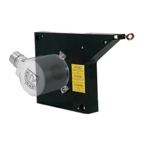
TR-Electronic CMW582M-4096/16 SSI SL00 3M Assembly Instructions Manual (237 pages)
Rotary Encoder construction size 58
Brand:
TR-Electronic
| Category:
Media Converter
| Size: 60 MB
Table of Contents
Deutsch
4
Table of Contents
4
Änderungs-Index
5
Allgemeines
6
Geltungsbereich / Typenschlüssel
7
Mitgeltende Dokumente
8
EU-Konformitätserklärung
8
Verwendete Abkürzungen und Begriffe
8
Allgemeine Funktionsbeschreibung
9
Absolut Encoder
9
Inkremental Encoder
11
Grundlegende Sicherheitshinweise
12
Symbol- und Hinweis-Definition
12
Verpflichtung des Betreibers vor der Inbetriebnahme
12
UL / CSA - Zulassung
13
Allgemeine Gefahren bei der Verwendung des Produkts
13
Bestimmungsgemäße Verwendung
14
Bestimmungswidrige Verwendung
14
Gewährleistung und Haftung
14
Personalauswahl und -Qualifikation; Grundsätzliche Pflichten
15
Organisatorische Maßnahmen
15
Sicherheitstechnische Hinweise
16
Transport / Lagerung
17
Montagehinweise / Schema
18
Vollwelle
18
Sacklochwelle
20
Hohlwelle
26
Kupplung
30
Zubehör
32
English
36
Revision Index
37
General Information
38
Applicability / Type Designation Code
39
Abbreviations and Definitions
40
EU Declaration of Conformity
40
Other Applicable Documents
40
Absolute Encoder
41
General Functional Description
41
Incremental Encoder
43
Basic Safety Instructions
44
Definition of Symbols and Instructions
44
Obligation of the Operator before Start-Up
44
General Risks When Using the Product
45
UL / CSA Approval
45
Intended Use
46
Non-Intended Use
46
Warranty and Liability
46
Organizational Measures
47
Personnel Qualification; Obligations
47
Safety Information's
48
Transportation / Storage
49
Instructions for Mounting / Schematic
50
Solid Shaft
50
Blind Shaft
52
Hollow through Shaft
58
Integrated Claw Coupling
62
Accessories
64
Änderungs-Index
69
Allgemeines
70
Geltungsbereich
70
Mitgeltende Dokumente
70
EU-Konformitätserklärung
71
Verwendete Abkürzungen und Begriffe
71
Messprinzip
72
Prinzipaufbau
72
Grundlegende Sicherheitshinweise
73
Symbol- und Hinweis-Definition
73
Verpflichtung des Betreibers vor der Inbetriebnahme
73
Allgemeine Gefahren bei der Verwendung des Produkts
74
UL / CSA - Zulassung
74
Bestimmungsgemäße Verwendung
75
Bestimmungswidrige Verwendung
75
Gewährleistung und Haftung
75
Organisatorische Maßnahmen
76
Personalauswahl und -Qualifikation; Grundsätzliche Pflichten
76
Sicherheitstechnische Hinweise
77
Transport / Lagerung
78
Montagevorschriften
79
Anwendungshinweise
80
Montage
80
Seilabzug
81
Sicherheit
81
Montagehinweise / Schema
82
Seilendring mit Kugelgelenk
82
Sl30
82
Sl00
83
Wds
83
Wps
84
Sl30
85
Wds
85
Zubehör
85
Revision Index
89
Applicability
90
General Information
90
Other Applicable Documents
90
Abbreviations and Definitions
91
EU Declaration of Conformity
91
Measuring Principle
92
Principle Structure
92
Basic Safety Instructions
93
Definition of Symbols and Instructions
93
Obligation of the Operator before Start-Up
93
General Risks When Using the Product
94
UL / CSA Approval
94
Intended Use
95
Non-Intended Use
95
Warranty and Liability
95
Organizational Measures
96
Personnel Qualification; Obligations
96
Safety Information's
97
Transportation / Storage
98
Mounting Rules
99
Application Notes
100
Mounting
100
Wire Pull-Off
101
Instructions for Mounting / Schematic
102
Sl30
102
Wire End Ring with Ball Joint
102
Sl00
103
Wds
103
Wps
104
Accessories
105
Sl30
105
Wds
105
Änderungs-Index
109
Allgemeines
110
Geltungsbereich / Typenschlüssel
110
Mitgeltende Dokumente
110
EU-Konformitätserklärung
111
Verwendete Abkürzungen und Begriffe
111
Grundlegende Sicherheitshinweise
112
Symbol- und Hinweis-Definition
112
Verpflichtung des Betreibers vor der Inbetriebnahme
112
Allgemeine Gefahren bei der Verwendung des Produkts
113
UL / CSA - Zulassung
113
Bestimmungsgemäße Verwendung
114
Bestimmungswidrige Verwendung
114
Gewährleistung und Haftung
114
Organisatorische Maßnahmen
115
Personalauswahl und -Qualifikation; Grundsätzliche Pflichten
115
Sicherheitstechnische Hinweise
116
Transport / Lagerung
117
Montage der Kupplung (Allgemein)
118
Montagehinweise / Schema
118
Vollwelle
118
Flansch-Montage
119
Klemmflansch-Montage
119
Servoklammern
120
Spannpratzen
121
Anforderungen an die Kundenwelle
122
Montage des Klemmrings (Allgemein)
122
Sacklochwelle / Hohlwelle
122
Klemmring Varianten
125
Federblech als Drehmomentstütze
126
Pass-Stift / Nuteinsatz
126
Gelenkstange als Drehmomentstütze
128
Integriertes Kupplungsstück
129
Zubehör
131
Revision Index
135
Applicability / Type Designation Code
136
General Information
136
Other Applicable Documents
136
Abbreviations and Definitions
137
EU Declaration of Conformity
137
Basic Safety Instructions
138
Definition of Symbols and Instructions
138
Obligation of the Operator before Start-Up
138
General Risks When Using the Product
139
UL / CSA Approval
139
Intended Use
140
Non-Intended Use
140
Warranty and Liability
140
Organizational Measures
141
Personnel Qualification; Obligations
141
Safety Information's
142
Transportation / Storage
143
Instructions for Mounting / Schematic
144
Mounting of the Coupling (General)
144
Solid Shaft
144
Clamping Flange Mounting
145
Flange Mounting
145
Servo Clamps
146
Clamping Jaws
147
Blind Hole Shaft / Hollow Shaft
148
Mounting of the Clamping Ring (General)
148
Requirements for the Customer Shaft
148
Clamping Ring Versions
151
Dowel Pin / Groove Insert
152
Spring Metal Sheet as Torque Holder
152
Joint Rod as Torque Holder
154
Integrated Coupling
155
Accessories
157
Inhaltsverzeichnis
161
Änderungs-Index
162
Allgemeines
163
Geltungsbereich
163
Verwendete Abkürzungen / Begriffe
164
Einsatz in Explosionsfähigen Atmosphären
165
Symbol- und Hinweis-Definition
165
Zusätzliche Sicherheitshinweise
165
SSI Informationen
166
Grundsätzliche Regeln
167
Installation / Inbetriebnahmevorbereitung
167
RS422 Übertragungstechnik
168
Anschluss - Hinweise
169
Kabelspezifikation
169
Anbindung an den PC (Programmierung)
170
V/R-Eingang (Optional)
171
SSI Schnittstelle
172
Grundparameter
173
Parametrierung über Trwinprog
173
Skalierungsparameter
173
Zählrichtung
173
Messlänge in Schritten
174
Umdrehungen Zähler / Umdrehungen Nenner
174
Messwertanfang
177
Presetfreigabe
177
Presetwert
177
Anzahl Datenbits
178
Code-Format
178
Format
178
Kein Sonderformat
178
Monozeit
178
Ssi
178
Prüfsumme
179
Bit Wiederholung
180
Negative Werte
182
Endschalter
183
Endschalter Ein/Aus
183
Position
183
Überdrehzahl 1/Min
183
Aufwärts Gegangen
184
Aufwärts Gehen, Abwärts Gehen
184
Bewegung
184
Endschalter
184
SSI-Sonderbits
184
Überdrehzahl
184
Parity Gerade, Fehlerparity Gerade
185
Statischer und Dynamischer Fehler (Watchdog)
185
Togglebit
185
Anzahl Impulse
186
Einheit
186
Geschwindigkeit
186
Inkremental (Optional)
186
Nullimpulsverknüpfung
187
Phase
187
Set K0
188
Signalpegel
188
Fehlerursachen und Abhilfen
189
Contents
193
Revision Index
194
Applicability
195
General Information
195
Abbreviations Used / Terminology
196
Additional Safety Instructions
197
Definition of Symbols and Instructions
197
Usage in Explosive Atmospheres
197
SSI Information
198
Basic Rules
199
Installation / Preparation for Commissioning
199
RS422 Data Transmission Technology
200
Cable Definition
201
Connection - Notes
201
Connection to the PC (Programming)
202
F/B Input (Optional)
203
SSI Interface
204
Basic Parameters
205
Count Direction
205
Parameterization Via Trwinprog
205
Scaling Parameters
205
Number of Revolutions - Numerator / - Divisor
206
Total Number of Steps
206
Origin Type
209
Preset Function
209
Preset Value
209
Check Sum
210
Format
210
No Special Format
210
Number of Data Bits
210
Ssi
210
SSI-Mono-Time
210
Transmit Code
210
26-Bit + Repeat
212
Negative Values
214
Cams
215
Cams On/Off
215
Overspeed 1/Min
215
Position
215
Cams
216
Going Up, Going down
216
Moving
216
Overspeed
216
SSI Special Bit
216
Encoder and Dynamic Error (Watchdog)
217
Even Parity, Even Error Parity
217
Toggle Bit
217
Incremental (Optional)
218
Number of Pulses
218
Speed
218
Unit
218
Phase
219
Set K0
220
Signal Level
220
Causes of Faults and Remedies
221
Advertisement
Advertisement
Related Products
TR-Electronic CMW582M 8192 PB SLG ME 2M Series
TR-Electronic CMW582M 4096 PB SLG ME 2M Series
TR-Electronic CMW582M-00054
TR-Electronic CMW582M-00003
TR-Electronic CMW582M-00015
TR-Electronic CMW582M-00002
TR Electronic CMH-58
TR-Electronic CMS582M-8192/4096 SSI DMS 12H7 KRF
TR-Electronic CM-58 Series
TR Electronic CMV-58
TR-Electronic Categories
Media Converter
Transducer
Measuring Instruments
Enclosure
DC Drives
More TR-Electronic Manuals
Login
Sign In
OR
Sign in with Facebook
Sign in with Google
Upload manual
Upload from disk
Upload from URL