Sign In
Upload
Manuals
Brands
Tomberlin Manuals
Offroad Vehicle
E-MERGE 2007
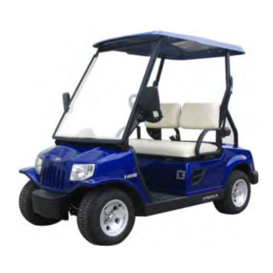
Tomberlin E-MERGE 2007 Manuals
Manuals and User Guides for Tomberlin E-MERGE 2007. We have
1
Tomberlin E-MERGE 2007 manual available for free PDF download: Maintenance Manual
Tomberlin E-MERGE 2007 Maintenance Manual (158 pages)
Brand:
Tomberlin
| Category:
Offroad Vehicle
| Size: 4 MB
Table of Contents
Introduction
3
Table of Contents
8
Safety Precautions
10
Preparation for an Emergency
10
Safe Use of Lubricating Oil
10
Safe Use of Battery
10
Vehicle Safety During Maintenance
11
Electrical Safety During Maintenance
11
Use the Designated Lifting Jack
14
Washing and Cleaning
15
Instrumentation for Electric Control System
15
Cautions
15
Use Appropriate Tools
15
Tightening Torque
16
Parts Replacement
16
Washer, Grease Fitting and O-Ring
16
Bearing and Oil Seal
16
Regular Inspection and Adjustment
17
Periodic Lubrication Plan
18
Braking System
20
Brake Inspection
20
Inspection of Parking Brake
21
Inspection of Brake Drum and Brake Shoe
22
Maximum Wearing Value of the Inside Diameter
23
Inspection of the Accelerator Pedal
25
Inspection of the Steering System
25
Inspection of the Steering Linkage
26
Removal of Drag Link Ball Joint
26
Inspection of Stub Axle
27
Inspection of the Front Wheel Alignment
27
Procedures for the Adjustment of Toe-In
28
Inspection of Tires and Wheel Rim
28
Inspection of the Shock Damper
29
Inspection of the Front Wheel Bearing
29
Inspection of the Rear Axle Bearing
29
Mounting Bolts of Front Shock Damper
30
Inspection of the Seat Belt
30
Binding Force of the Seat Belt
30
Removal of the Canopy
32
Removal of Canopy Rods
32
Removal of the Pillar
33
Removal of the Rear Bumper
35
Removal of the Rear Tray
35
Removal of the Front Bumper
35
Body
35
Removal of the Seat Cushion
37
Removal of Front Cover
39
Removal of the Dashboard
40
Removal of the Rear Cover
41
Rear Cover
43
Front Axle
44
Removal of the Front Axle
45
Driving Axle
51
Removal of the Driving Axle
52
Gearbox
58
Removal of the Differential Gear
59
Brake System
63
Brake Pedal
64
Parking Brake Handle
64
Accelerator Pedal
66
Steering System
67
Removal of the Steering Gear
69
Disassembly of the Steering Gear
69
Removal of Forward/Reverse Gear Switch
74
Key Switch Removal
74
Key Switch Installation
74
Electric Component
74
Installation of Forward/Reverse Gear Switch
75
Battery Discharge Meter Removal
75
Battery Discharge Meter Installation
76
Horn Removal
76
Horn Installation
76
Combination Switch Removal
77
Combination Switch Installation
77
Control Circuit
78
Controller Removal
78
Controller Installation
79
Charger Receptacle Removal
80
Charger Receptacle Installation
80
Battery Removal
80
Battery Installation
80
DC Converter Removal
81
DC Converter Installation
81
Removal of DC Changeover Contactor and Diode Assembly
82
Installation of DC Changeover Contactor and Diode Assembly
83
Motor Removal
83
Exciting Circuit Opening
85
Motor Installation
85
Removal of Bulb of Headlight and Front Turn Signal Light
86
Headlight Installation
86
High Mount Stop Lamp Removal
87
Tail Light Removal
87
High Mount Stop Lamp Disassembly
88
High Mount Stop Lamp Installation
88
Troubleshooting
89
Index for Check Procedures
91
Motor Voltage at A1 and A2
92
TOW/RUN Switch
92
Accelerator Signal Voltage
92
Battery/ Voltage Check
92
Circuit Check for Key Switch and Accelerator Pedal Switch
93
Battery Voltage
93
Controller Signal
95
Check Proce Dure 7C
96
Motor Speed Sensor
98
Reverse Buzzer
99
Battery Discharge Meter
99
High Mount Stop Lamp
100
Wiper
100
Flashing Light
100
Discharging Battery
119
Battery and Charger
119
Battery Overview
119
Schematic Diagram of Charged Battery
119
Common Misconceptions about Battery
120
Premature Excessive Discharge
120
Battery Replacement
121
Battery Maintenance
122
Preventative Maintenance
122
Self Discharge
123
Electrolyte Liquid Level
123
Liquid Level of Battery Solution
123
Battery Charging
124
Mineral Content
124
Vibration Damage
124
Deep Discharge
125
Premature Excessive Discharge
125
Electric Vehicle and Charger Numbering
125
AC Power Supply Line
125
Battery Troubleshooting Diagram
126
Inspection with Hydrometer
127
Inspection and Test of the Battery Charger
127
Charging Voltage Inspection
127
Inspection and Test of the Battery
127
Hydrometer Inspection Result Presentation
128
Calibration of Hydrometer
128
Discharge Test
129
Discharge Test Result Presentation
130
Procedures for Discharge Test
130
Battery Troubleshooting Example
131
Charge of the Battery Pack with Low Electric Quantity
132
Battery Storage
132
Conditions to be Noted before Charging
133
B Attery Charger
133
Removal of the Charger
134
Get to Know the Charger
134
Continuity Inspection
135
Maintenance of the Battery Charger
135
Procedures for Component Replacement
136
Diode Test Procedure
136
Charger Trouble-Shooting Procedure
137
Troubleshooting
137
On-Board Charger
139
Open Excitation Circuit
143
Internal Short Circuit
143
Disconnection of Armature Circuit
143
Exterior Inspection of the Electric Motor
143
Removal of the Electric Motor
145
Inspection and Test of the Motor Element
145
Inspection of the Armature
145
Armature Earth Test
146
Inspection of the Excitation Winding
147
Motor Element
147
Removal of the Speed Sensor Magnet
148
Removal of the Bearing
148
Mounting of the Bearing
148
Bearing Inspection
148
Readjustment of the Electric Motor
149
Specifications for the Electric Motor
150
Assembly of the Electric Motor
151
Mounting of the Electric Motor
153
Inspection of the Speed Sensor of the Electric Motor
156
Removal of the Speed Sensor
156
Mounting of the Speed Sensor of Electric Motor
156
Advertisement
Advertisement
Related Products
Tomberlin E-MERGE
Tomberlin E-Merge E2
Tomberlin E-Merge E2 LE
Tomberlin E-Merge E2 SS
Tomberlin 2010 E-Merge
Tomberlin Anvil
Tomberlin FireFox 620
Tomberlin Categories
Offroad Vehicle
Automobile Accessories
Utility Vehicle
Golf Cars
Motorized Toy Car
More Tomberlin Manuals
Login
Sign In
OR
Sign in with Facebook
Sign in with Google
Upload manual
Upload from disk
Upload from URL