Sign In
Upload
Manuals
Brands
Thrane&Thrane Manuals
Boating Equipment
SAILOR 900 VSAT System
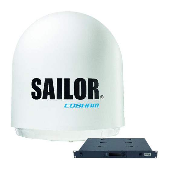
Thrane&Thrane SAILOR 900 VSAT System Manuals
Manuals and User Guides for Thrane&Thrane SAILOR 900 VSAT System. We have
4
Thrane&Thrane SAILOR 900 VSAT System manuals available for free PDF download: Installation & Service Manual, Installation & User Manual, Quick Manual
Thrane&Thrane SAILOR 900 VSAT System Installation & Service Manual (348 pages)
Brand:
Thrane&Thrane
| Category:
Marine Radar
| Size: 19 MB
Table of Contents
Table of Contents
9
Chapter 1 About this Manual
29
Intended Readers
29
Manual Overview
29
Chapter 8 Daily Use - Quick Guide
29
Chapter 2 Introduction
29
Chapter 9 Service & Maintenance
29
Software Version
30
Related Documents
30
Typography
30
Chapter 1 About this Manual
30
Table 1-1: List of Related Documents
30
Precautions
31
Chapter 2 Introduction
33
SAILOR 900 VSAT System
33
Overview
33
Figure 2-1: above Deck Unit and Antenna Control Unit (ACU)
34
Figure 2-2: above Deck Unit and Antenna Control Unit (ACU), 19" Rack Version
34
Chapter 2 Introduction
35
Above Deck Unit (ADU)
36
Figure 2-3: above Deck Unit (ADU)
36
Figure 2-4: above Deck Unit Modules 1/2
37
Figure 2-5: above Deck Unit Modules 2/2
38
Antenna Control Unit (ACU)
40
Figure 2-6: SAILOR 900 VSAT ACU, Connector Overview
40
Figure 2-7: SAILOR 900 VSAT ACU, 19" Rack Version
41
Figure 2-8: Antenna Control Unit for Bulkhead Installation
41
Figure 2-9: Antenna Control Unit for 19" Rack Installation
41
VSAT Modem Unit (VMU)
42
Satellite Type Approvals
42
Power Supply (Optional)
42
Service Activation
42
Part Numbers and Options
43
Applicable Thrane & Thrane Model and Part Numbers
43
Options for SAILOR 900 VSAT
43
Table 2-1: Model and Part Numbers for the SAILOR 900 VSAT System (T&T Units)
43
Chapter 3 Installation
45
Unpacking
45
What's in the Box
45
Initial Inspection
46
Tools Needed
47
Site Preparation
47
General Site Considerations
47
Obstructions (ADU Shadowing)
48
Figure 3-1: Signal Degradation Because of Obstructing Objects
48
Blocking Zones - Azimuth and Elevation
49
Figure 3-2: 2 Blocking Zones with No-Transmit Zones, Azimuth (Example)
49
Figure 3-3: Blocking Zone with No-Transmit Zones, Elevation Angle (Example)
49
Safe Access to the ADU: Radiation Hazard
50
Figure 3-4: Radiation Hazard, Safety Distance 30 M
50
Ship Motion and Offset from the Ship's Motion Centre
51
Figure 3-5: Maximum Distance from the Ship's Motion Centre (H Max)
51
Table 3-1: Maximum Distance from the Ship's Motion Center Versus Ship's Roll Period
51
ADU Mast Design: Foundation and Height
52
Figure 3-6: ADU Mast Flange, Top and Side View
52
Figure 3-7: ADU Mast Flange, Recommended Flatness on the Mast Mount Plateau
52
Figure 3-8: ADU Mast Flange, Distance to the Welded Seam
53
Figure 3-9: ADU, Bottom View
53
Figure 3-10: Free Mast Length and Bracing for a Tall Mast
54
Table 3-2: Mast Dimensions Without Braces
55
Table 3-3: Mast Dimensions with 3 Braces
55
Table 3-4: Mast Dimensions with 2 Braces
56
Interference
57
Figure 3-11: Interference with the Vessel's Radar
58
Table 3-5: Minimum Radar Separation, X-Band
58
Table 3-6: Minimum Radar Separation, S-Band
59
Figure 3-12: Recommended Distance to Transmitters (M) for Frequencies below 1000 Mhz
60
Other Precautions
61
Figure 3-13: Drain Pipe with Free Space
61
Installation of the ADU
62
Figure 3-14: Use of Strong Sling with a Belt and Tag Lines for Safe Hoisting
62
Installing the ADU
63
Figure 3-15: Free Space for Access to the Service Hatch
63
Figure 3-16: ADU Installation, Webbed Sling Attached to the 4 Lifting Brackets
64
Figure 3-17: Mounting the ADU on the Mast Flange
64
Figure 3-18: Connecting the ADU Cable
65
Opening and Removing the Service Hatch
66
Figure 3-19: Opening the Service Hatch
66
Figure 3-20: Removing the 2 Split Pins
66
Grounding the ADU
67
Figure 3-21: Removing the Service Hatch
67
Figure 3-22: ADU, Bolt for Optimum Grounding
68
Alternative ADU Cable
69
Table 3-7: ADU Cable Types and Maximum Lengths
69
Installation of the ACU (Bulkhead)
70
Installing the ACU (Bulkhead)
70
Figure 3-24: ACU, Connector Panel
70
Grounding the ACU (Bulkhead)
71
Figure 3-25: SAILOR 900 VSAT ACU, Bulkhead Version, Ground Stud
71
SAILOR 900 VSAT ACU (Bulkhead) with Cable Support
72
Figure 3-28: Mounting the Cable Relief 2/2
73
Installation of the 19" Rack Version of the ACU
74
Installing the 19" Rack Version of the ACU
74
Figure 3-29: ACU, 19" Rack Version, On/Off Switch at the Back
74
Grounding the 19" Rack Version of the ACU
75
Figure 3-30: ACU, LAN Connector at the Front: Service Port
75
Figure 3-31: ACU, 19" Rack Version, Ground Stud
75
Installation of the VMU
76
General Mounting Considerations - VMU
76
Installing the Dual-Antenna Mode (Optional)
77
Figure 3-32: Dual Mode Antenna, Overview
77
Figure 3-33: Dual Mode Antenna, Connecting Cables (Example)
78
Table 3-8: Dual Mode Antenna, Cabling
78
Chapter 4 Interfaces
79
Interfaces of the SAILOR 900 VSAT ACU
79
ACU Bulkhead - Leds, Display and Keypad
79
ACU 19" Rack Version - Leds, Display and Keypad
79
Figure 4-1: ACU Bulkhead, Leds, Display and Keypad
79
Figure 4-2: ACU Rack Version, Leds, Display and Keypad
79
ACU Bulkhead - Connector Panel - Overview
80
Figure 4-3: ACU Bulkhead, Connector Panel Overview
80
Figure 4-4: ACU Rack Version, Connector Panel Overview
80
DC Input Connector
81
Figure 4-5: DC Input Connector with Power Cable
81
Table 4-1: DC Input Plug, Outline and Pin Assignment
81
ADU Connector
82
Rx/Tx Connectors for VMU
82
Table 4-2: N Connector, Outline and Pin Assignment
82
Table 4-3: F Connector, Rx and Tx, Outline and Pin Assignment
82
NMEA 0183 Connector (RS-422)
83
Table 4-4: NMEA 0183/2000 Connector, Outline and Pin Assignment
83
And RS-422 Connectors
84
Table 4-5: RS-232 Connector, Male, Outline and Pin Assignment
84
LAN1, LAN2, LAN3 and LAN4 Connectors
85
Figure 4-6: LAN1 -LAN4 Connectors
85
Table 4-6: RS-422 Connector, Male, Outline and Pin Assignment
85
Table 4-7: Ethernet Connector, Outline and Pin Assignment
86
Interfaces of the VMU
87
Connecting an Infiniti® Series Satellite Router
87
Figure 4-7: Connecting an Infiniti® Series Satellite Router
87
Table 4-8: Cables to Connect an Infiniti® Series Satellite Router
87
Connecting an Evolution® Satellite Router
88
Connecting a Comtech 570 L or 625 Satellite Modem
88
Figure 4-8: Connecting an Evolution Satellite Router
88
Figure 4-9: Connecting a Comtech 570 L or 625 Satellite Modem
88
Table 4-9: Cables to Connect a Comtech 570 L-Band Satellite Modem
88
Connecting a Satlink2900 VSAT Modem
89
Figure 4-10: Connecting a Satlink 2900 Modem
89
Table 4-10: Cables to Connect a Satlink 2900 VSAT Modem
89
Connecting a Gilat Skyedge II VSAT Modem
90
Figure 4-11: Connecting a Gilat Skyedge II VSAT Modem
90
Table 4-11: Cables to Connect a Gilat Skyedge VSAT Modem
90
Chapter 5 Connecting Power
91
Power Source
91
Power Cable Selection
92
Source Impedance
92
Measuring the Ship Source Impedance
92
Power Cable Recommendations
93
Figure 5-1: Measuring the Ship Source Impedance
93
Connecting Power
94
Figure 5-2: Connecting Power to DC Input
94
Power up
95
Figure 5-3: ACU Display after First Power on (Example with LAN Ports 1 and 4 Used)
95
Chapter 6 Configuration
97
Introduction to the Built-In Web Interface
97
Overview
97
Figure 6-1: Configuration Setup
97
Connecting to the Web Interface
98
Figure 6-2: LAN Connector Used for Configuring the SAILOR 900 VSAT
98
Figure 6-3: SAILOR 900 VSAT Dashboard
99
Calibration of the SAILOR 900 VSAT
100
Preparing for Calibration
100
Figure 6-4: Service Profile for Calibration
101
Table 6-1: Satellite Requirements for Elevation and Carrier
101
Heading and Calibration of Azimuth and Cable
102
Figure 6-5: Web Interface: SERVICE, Calibration
102
Table 6-2: Satellite Identifier and NID Values
104
Table 6-3: Possible Error Codes During Calibration
105
Flow Chart for Azimuth and Cable Calibration
106
Figure 6-6: Example for Azimuth and Cable Calibration - Step by Step
106
Line up Procedure
107
Figure 6-7: Web Interface: SERVICE, Line Up: Ready for Activation
107
Figure 6-8: Web Interface: SERVICE, Line Up: Antenna Ready
108
SAILOR 900 VSAT Fixed TX Gain Principle
109
Figure 6-9: Fixed TX Gain Principle
109
Configuration with the Web Interface
110
Overview and Navigation
110
Figure 6-10: Topics in the Web Interface (SITE MAP)
110
Figure 6-11: Sections of the Web Interface
111
Table 6-4: Web Interface: Event Icon
112
Using the Dashboard
114
Figure 6-12: Web Interface: DASHBOARD
114
Table 6-5: Web Interface, DASHBOARD, SAILOR 900 VSAT Parameters
115
Table 6-6: Web Interface, DASHBOARD, VSAT MODEM Parameter
116
Table 6-7: Web Interface, DASHBOARD, POINTING Parameter
116
Satellite Profiles and VSAT Modem Profiles
117
Figure 6-13: Web Interface: SETTINGS - List of Satellite Profiles (Example)
117
Figure 6-14: Web Interface: SETTINGS, Satellite Profiles - New Entry (Example)
118
Table 6-8: Elevation Cutoff (in Degrees) Versus VSAT Modem Bandwidth and Power
119
Figure 6-15: Web Interface: SETTINGS, VSAT Modem Profiles - List (Example)
120
Figure 6-16: Web Interface: SETTINGS, VSAT Modem Profiles - New Entry (Example)
121
Figure 6-18: Satellite Profile for Generic Modem
122
Setting up Blocking Zones (RX and TX)
123
Figure 6-19: Web Interface: SETTINGS, Blocking Zones - Azimuth and Elevation
123
Figure 6-20: Blocking Zone, Example: 315 - 45 Degrees
124
Figure 6-21: Blocking Zone, Example: 45 - 315 Degrees
124
Configuring the LAN Network
125
Figure 6-22: Web Interface: SETTINGS, Network (Default Settings)
125
Table 6-9: Setup of LAN Connectors
126
E-Mail Setup
128
Figure 6-23: Web Interface: SETTINGS, E-Mail Setup (Example)
128
Sending Statistics Reports
129
Figure 6-24: Web Interface: SETTINGS, Reports (Example)
129
Figure 6-25: Statistics - How to Read Data for a Range
130
Table 6-10: Statistics Report, Header Record
130
Table 6-11: Parameters Recorded in a Statistics Report
130
Sending a Diagnostics Report
132
Figure 6-26: Statistics Report (Example)
132
Dual Antenna Mode (Optional)
133
Figure 6-27: Dual-Antenna Mode, Link on DASHBOARD
133
Figure 6-28: Enabling Dual-Antenna Mode in Master ACU
134
Figure 6-29: Dual-Antenna Mode, Add Slave Modem Profile
135
Figure 6-30: Dual-Antenna Mode, Add Slave Satellite Profile
136
Figure 6-31: Dual-Antenna Mode, Activate
136
Figure 6-32: Dual-Antenna Mode, Blocking Zones - Azimuth and Elevation
137
Upload
138
Figure 6-33: Dual-Antenna Mode, Line up
138
Administration
139
Figure 6-34: Web Interface: Administration
139
Figure 6-35: Web Interface: Administration, Change Administrator Logon and Password
140
Figure 6-36: Web Interface: ADMINISTRATION, Reset Administrator Password
140
Figure 6-37: Web Interface: ADMINISTRATION, User Permissions
141
Figure 6-38: Web Interface: Administration, Export/Import Configuration
142
Figure 6-39: Web Interface: ADMINISTRATION, Factory Default
144
Keypad and Menus of the ACU
145
ACU Display and Keypad
145
Figure 6-40: Display (Example) and Keypad of the ACU
145
Navigating the Menus
146
The Menu Tree
147
Figure 6-41: Antenna Control Unit, Menu Tree
147
Table 6-12: Top-Level Menus of the ACU
148
Table 6-13: ANTENNA Menu of the ACU
148
Table 6-14: MODEM Menu of the ACU
149
Table 6-15: NETWORK Menu of the ACU
149
Table 6-16: SATELLITE Menu of the ACU
149
Adjusting Brightness of the Display
150
Table 6-17: EVENTS Menu of the ACU
150
Resetting the System
151
SNMP Support
151
Figure 6-42: Reset the System
151
Chapter 3 Installation
29
Chapter 4 Interfaces
29
Chapter 5 Connecting Power
29
Chapter 6 Configuration
29
Chapter 7 Installation Check
153
Installation Check List: Antenna
153
Table 7-1: Installation Check List: Antenna
154
Installation Check List: ACU, Connectors and Wiring
155
Table 7-2: Installation Check List: ACU, Connectors and Wiring
156
Installation Check List: Functional Test in Harbor
157
Table 7-3: Installation Check List: Functional Test in Harbour
157
Chapter 8 Daily Use - Quick Guide
159
Figure 8-1: SAILOR 900 VSAT Quick Guide - Web Interface and Satellite Profiles
159
Figure 8-2: SAILOR 900 VSAT Quick Guide - Viewing System Parameters
160
Chapter 9 Service & Maintenance
161
Getting Support: Helpdesk
162
Help Desk and Diagnostic Report
162
Figure 9-1: Web Interface: HELPDESK
162
Figure 9-2: Web Interface: HELPDESK, Event List
163
Software Update
165
Hardware and Software Requirements
165
Software Update (ADU and ACU)
165
Figure 9-3: LAN Connector Used for Configuring the SAILOR 900 VSAT
165
Verifying the Software Update
166
Figure 9-4: Verifying Software Update
167
Status Signalling with Leds and Status Messages
168
Overview
168
Leds of the ADU Modules
169
Table 9-1: Leds of the ADU Modules
169
Leds in the ACU
170
Figure 9-5: Leds on the ACU
170
Figure 9-6: Leds on the ACU, 19" Rack Version
170
Table 9-2: Leds on the ACU
170
Removal and Replacement of the ACU
171
Figure 9-7: Removal and Replacement of the ACU Bulkhead
171
Figure 9-8: Removal and Replacement of the ACU 19" Rack
171
Removal and Replacement of ADU Modules
172
Overview
172
Figure 9-9: ADU Modules and Motor Stop Switch
172
Figure 9-10: Service Switch
176
Figure 9-11: above Deck Unit Modules (Continued)
177
Replacing the GPS Module
178
Figure 9-12: GPS Module
178
Figure 9-13: Switch off the Power to the Antenna
179
Figure 9-14: GPS Module Facing the Service Hatch
179
Figure 9-15: Connector for GPS PCB
180
Figure 9-16: Screws on GPS Module
180
Replacing the VSAT Interface Module (VIM)
181
Figure 9-17: VSAT Interface Module (VIM)
181
Figure 9-18: Location of the VIM
181
Figure 9-19: Replacing the VIM - Remove 2 F-Connectors
182
Figure 9-20: Replacing the VIM - Remove 2 N, 2 F, 1 SMA and 1 SUB-D Connectors
182
Figure 9-21: Replacing the VIM - Remove 4 allen Screws
183
Replacing the DC-Motor Driver Module (DDM)
184
Figure 9-22: DC-Motor Driver Module (DDM) for Cross Elevation
184
Figure 9-23: Location of the Cross Elevation DDM
185
Figure 9-24: Replacing the DDM - Remove Connectors
185
Figure 9-25: Location of the Elevation DDM
186
Figure 9-26: Elevation DDM, Connectors
186
Figure 9-27: Location of the Azimuth DDM
187
Replacing the Polarisation Motor Module (PMM)
188
Figure 9-28: Azimuth DDM, Connectors
188
Figure 9-29: Polarisation Motor Module, Remove Connectors
189
Figure 9-30: Polarisation Motor Module, Remove Screws
190
Figure 9-31: Polarisation Motor Module, Inserting
191
Replacing the Pedestal Control Module (PCM)
192
Figure 9-32: Location of the PCM
192
Figure 9-33: Removing the PCM - Connectors
193
Replacing Motor and Encoder
194
Figure 9-34: Motors and Encoders
194
Figure 9-35: Location of the Elevation Motor & Encoder
195
Figure 9-36: Elevation Motor and Encoder, Loosen the Belt Tensioner
195
Figure 9-37: Elevation Motor and Encoder, Adjust Belt Tension
196
Figure 9-38: Elevation DDM, Disconnect 2 Connectors
196
Figure 9-39: Elevation Motor and Encoder, Loosen the Screws for the Motor Assembly
197
Figure 9-40: Elevation Motor and Encoder, Tighten the Screws for the Motor Assembly
198
Figure 9-41: Elevation Motor and Encoder, Adjust Belt Tension
198
Figure 9-42: Elevation Motor and Encoder, Check of Belt Tension
199
Figure 9-43: Elevation Motor and Encoder, Loosen the Belt Tensioner
199
Figure 9-44: Azimuth Motor, Remove Cover
201
Figure 9-45: Azimuth Motor, Loosen the Belt Tensioner
201
Figure 9-46: Azimuth Motor, Adjust Belt Tension
202
Figure 9-47: Azimuth DDM, Disconnect Connector
202
Figure 9-48: Azimuth Motor, Loosen the Screws for the Motor Assembly
203
Figure 9-49: Azimuth Motor, Tighten the Screws for the Motor Assembly
204
Figure 9-50: Azimuth Motor, Adjust Belt Tension
204
Figure 9-51: Azimuth Motor, Tighten the Belt Tensioner
205
Figure 9-52: Azimuth Encoder, Remove Cover
206
Figure 9-53: Azimuth DDM, Disconnect Connector
206
Figure 9-54: Azimuth Encoder, Remove
207
Figure 9-55: Azimuth Encoder, Adjust Belt Tension
207
Figure 9-56: Azimuth Encoder, Adjust Belt Tension
208
Figure 9-57: Azimuth Motor, Tighten the Belt Tensioner
208
Figure 9-58: Replacement of X-Elevation Motor & Encoder 1
209
Figure 9-59: X-Elevation Motor & Encoder - Belt Tension/Adjustment Screw
210
Figure 9-60: Cross Elevation Motor Assembly, 4 allen Screws
210
Figure 9-61: Cross Elevation Motor Assembly, Do Not Tighten Screws
211
Figure 9-62: X-Elevation Motor & Encoder - Adjust Belt Tension
211
Figure 9-63: Belt Tension in 3 Positions
212
Figure 9-64: Cross Elevation Motor Assembly, Tighten Screws
212
Figure 9-65: Polarisation Motor, Disconnecting Power
213
Figure 9-66: Polarisation Motor, Removing 4X4 MM allen Screws
213
Figure 9-67: Removing the Sub-D Connector of the PMM
214
Figure 9-68: Polarisation Encoder, Removing
214
Replacing the Drive Belts
215
Figure 9-69: Location of the X Elevation Drive Belt
215
Figure 9-70: Removing the Cable Drum
216
Figure 9-71: Location of the Elevation Drive Belt
217
Figure 9-72: Elevation Drive Belt
217
Figure 9-73: Elevation Motor and Encoder, Loosen the Belt Tensioner
218
Figure 9-74: Elevation Motor and Encoder, Adjust Belt Tension
218
Figure 9-75: Elevation Drive Belt
219
Figure 9-76: Azimuth Drive Modules, Remove Cover
220
Figure 9-77: Azimuth Drive Belt, Loosen the Belt Tensioner
221
Figure 9-78: Azimuth Drive Belt, Adjust Belt Tension
221
Figure 9-79: Getting Access to the Azimuth Drive Wheel
222
Figure 9-80: Azimuth Drive Belt
222
Replacing the Zero Reference Module (ZRM)
223
Figure 9-81: Zero Reference Modules (ZRM), Location
223
Figure 9-82: Zero Reference Module (ZRM)
223
Figure 9-83: X Elevation ZRM, Disconnect Connector
225
Figure 9-84: X Elevation ZRM, Slide out
225
Figure 9-85: Elevation ZRM, Disconnect Connector
226
Figure 9-86: Elevation ZRM, Remove Screws
227
Figure 9-87: Azimuth ZRM, Remove Cover
228
Figure 9-88: Azimuth ZRM, Disconnect Connector
228
Figure 9-89: Azimuth ZRM, Disconnect Connector
229
Figure 9-90: Polarisation ZRM, Disconnecting
229
Replacing the Inertial Sensor Module (ISM)
230
Figure 9-91: Polarisation ZRM, Loosen 2X4 MM allen Screws
230
Figure 9-92: Inertial Sensor Module (ISM), Location
230
Figure 9-93: Inertial Sensor Module (ISM)
231
Figure 9-94: Removing the ISM
232
Figure 9-95: Removing the ISM Sub D Connectors
232
Replacing the Polarisation Unit
233
Figure 9-96: Removing the Sub-D Connector of the PMM
234
Figure 9-97: Disconnecting the Lnbs
235
Figure 9-98: Removing the Cable Spool
235
Figure 9-99: Disconnecting the OMT Connector
236
Figure 9-100: Disconnecting the OMT Connector
236
Replacing the BUC Fan
237
Figure 9-101: Removing the BUC Fan
237
Replacing the Block up Converter (BUC)
238
Figure 9-102: Block up Converter (BUC), Location
238
Figure 9-103: Block up Converter (BUC)
238
Figure 9-104: BUC, Removing
239
Figure 9-105: BUC, Removing (Continued)
239
Replacing the Low Noise Block down Converter (LNB)
240
Figure 9-106: Low Noise Block (LNB)
240
Figure 9-107: LNB, Removing
241
Figure 9-108: LNB, Removing (Continued)
241
Replacing the Ortho Mode Transducer (OMT)
242
Figure 9-109: Ortho Mode Transducer (OMT)
242
Figure 9-110: OMT, Removing 2Xtorx20 Screws on Top
243
Figure 9-113: OMT, Removing
244
Replacing the Rotary Joint
245
Figure 9-114: OMT, Removing the Waveguide
245
Figure 9-115: Rotary Joint
245
Figure 9-116: Azimuth Motor, Remove Cover
246
Figure 9-117: Getting Access to the Azimuth Drive Wheel
247
Figure 9-118: Rotary Joint (in Place)
247
Figure 9-119: Rotary Joint (Removed)
248
Updating VIM/PCM Calibration Data
249
Figure 9-120: Updating VIM/PCM Calibration Data (Example)
249
Figure 9-121: XIM Data, Warning
249
Figure 9-122: XIM Data Not Ready
250
Figure 9-123: XIM Data Valid
250
Troubleshooting
251
Overview
251
Event List for Troubleshooting
251
Diagnostic Report for Troubleshooting
251
Troubleshooting - BUC
252
Figure 9-124: Troubleshooting - BUC
252
Troubleshooting - LNB
253
System Block Diagram (ADU)
253
Figure 9-125: Troubleshooting - LNB
253
Table A-1: General Specifications
257
A.1 SAILOR 900 VSAT System Components
257
Appendix A Technical Specifications
258
Adu
258
Table A-2: Technical Specifications for the above Deck Unit
258
A.1.2 Adu
258
Acu
260
Table A-3: Technical Specifications for the ACU
260
A.1.3 Acu
260
Supported VSAT Modems
261
Table A-4: Supported VSAT Modems
261
Outline Drawings
262
Adu
262
Figure A-1: Outline Drawing: ADU
262
A.2 Outline Drawings
262
ACU, Bulkhead
263
Figure A-2: Outline Drawing: ACU, Bulkhead
263
ACU, 19 Inch Rack
264
Figure A-3: Outline Drawing: ACU, 19 Inch Rack
264
N-Connector Interface on the ADU
265
Figure A-4: N-Connector Interface on the ADU
265
VSAT LNB Data Sheet (Physical LNB
266
VSAT LNB User Installation and Configuration Information
266
Table A-5: Technical Specifications for VSAT LNB
266
Table A-6: 4-Band Switching
267
Table
267
VSAT 8 W BUC Data Sheet (Extended
268
Table A-7: Technical Specifications for VSAT 8 W BUC
268
Modem Cable Comtech Serial & RSSI TT7016A
269
Figure B-1: Modem Cable Comtech Serial & RSSI TT7016A
270
Modem Cable Inifiniti Idirect VSAT Modem
271
Appendix B VMU Cable Specifications
274
Appendix Cvmu Settings Requirements
274
Open AMIP Setup for Idirect INFINITI & Evolution
274
Protocol and Interfaces
274
Figure C-1: Connecting Idirect Infiniti 5000 Series to the ACU (Openamip
275
Figure C-2: Connecting Idirect Evolution X5 to the ACU (Openamip
275
Figure C-3: Supported Openamip Commands
276
Table C-1: Messages Sent from the VSAT Modem to the ACU (Examples
276
Sample Options File
277
Table C-2: Messages Sent from the ACU to the VSAT Modem (Examples
277
Table C-3: Ranges for Signal Strength for Idirect Open AMIP VSAT Modem
277
Table C-4: Information in the VSAT Modem Option File
279
Configuration Examples (Openamip
280
Figure C-4: VSAT Modem Profile, Openamip (Example
280
Figure C-5: Satellite Profile, Openamip (Example
280
Non-Open-AMIP Setup for Idirect Infiniti 5000 & Evolution X5
281
Protocol and Interfaces
281
Figure C-6: Connecting Idirect Infiniti 5000 Series to the ACU (Non-Openamip
281
Console Port Settings
282
Figure C-7: Connecting Idirect Evolution X5 to the ACU (Non-Openamip
282
Figure C-8: RS-232 Console Cable for Idirect Non-Openamip VSAT Modem
282
Table C-5: Requirements for VSAT Modem Option File, Non-Openamip
283
Configuration Examples (Non-Openamip
284
Figure C-9: VSAT Modem Profile, Non-Openamip (Example
284
Figure C-10: Satellite Profile, Non-Openamip (Example
285
Comtech 570L, ROSS Box & ACU
286
Protocols and Interfaces
286
Figure C-11: Connecting Comtech 570L and ROSS Box to the ACU (Example
286
STM Satlink 2900 VSAT Modem
287
Interfaces and VSAT Modem Configuration
287
Figure C-12: Connecting Satlink 2900 VSAT Modem to the ACU
287
ACU Configuration
288
Gilat Skyedge II VSAT Modem
289
Interfaces and VSAT Modem Configuration
289
Figure C-13: Connecting Gilat Skyedge II VSAT Modem to the ACU
289
ACU Configuration
290
Table C-6: Configuration of Gilat Skyedge II VSAT Modem
290
Appendix D Command Line Interface
291
Introduction
291
Figure D-1: How to Use the Command Line Interface (Example for Telnet
291
D.1 Introduction
291
Telnet Connection
292
Help
292
Figure D-2: Command Line Interface, Login
292
D.1.1 Telnet Connection
292
Conventions
293
Table D-1: Command Typography
293
D.1.3 Conventions
293
Supported Commands
294
Config
294
Demo
294
Table D-2: UCLI Command: Config
294
Table D-3: UCLI Command: Demo
294
D.2 Supported Commands
294
Dual_Antenna
295
Exit
295
Help
295
Table D-5: UCLI Command: Exit
295
Modem
296
Satellite
296
Table D-6: UCLI Command: Help
296
Table D-7: UCLI Command: Modem
296
Table D-8: UCLI Command: Satellite
296
System
299
Table D-9: UCLI Command: Status
299
D.2.8 Status
299
Track
300
Zone
301
Table E-1: Examples of DVB-S Satellites for Azimuth Calibration
303
Advertisement
Thrane&Thrane SAILOR 900 VSAT System Installation & User Manual (244 pages)
Brand:
Thrane&Thrane
| Category:
Boating Equipment
| Size: 12 MB
Table of Contents
Safety Summary
5
Table of Contents
9
Chapter 1 About this Manual
23
Intended Readers
23
Manual Overview
23
Software Version
23
Typography
24
Precautions
24
Chapter 1 About this Manual
24
Chapter 2 Introduction
25
SAILOR 900 VSAT System
25
Figure 2-1: above Deck Unit and Antenna Control Unit (ACU), 19" Rack Version
25
Above Deck Unit (ADU)
26
Figure 2-2: above Deck Unit (ADU)
26
Figure 2-3: above Deck Unit Modules 1/2
27
Figure 2-4: above Deck Unit Modules 2/2
28
Antenna Control Unit (ACU)
29
Figure 2-5: SAILOR 900 VSAT ACU, Connector Overview
30
Figure 2-6: SAILOR 900 VSAT ACU, 19" Rack Version
30
Chapter 2 Introduction
30
Chapter 3 Installation
30
VSAT Modem Unit (VMU)
31
Satellite Type Approvals
31
Power Supply (Optional)
31
Service Activation
31
Figure 2-7: Antenna Control Unit for 19" Rack Installation
31
Part Numbers and Options
32
Applicable Thrane & Thrane Model and Part Numbers
32
Options for SAILOR 900 VSAT
32
Table 2-1: Model and Part Numbers for the SAILOR 900 VSAT System
32
Table 2-2: Model and Part Numbers for Options of the SAILOR 900 VSAT System
32
Chapter 3 Installation
33
Unpacking
33
What's in the Box
33
Initial Inspection
34
Tools Needed
34
Site Preparation
35
General Site Considerations
35
Obstructions (ADU Shadowing)
36
Figure 3-1: Signal Degradation Because of Obstructing Objects
36
Blocking Zones - Azimuth and Elevation
37
Figure 3-2: 2 Blocking Zones with No-Transmit Zones, Azimuth (Example)
37
Figure 3-3: Blocking Zone with No-Transmit Zones, Elevation Angle (Example)
37
Safe Access to the ADU: Radiation Hazard
38
Figure 3-4: Radiation Hazard, Safety Distance 30 M
38
Ship Motion and Offset from the Ship's Motion Centre
39
Figure 3-5: Maximum Distance from the Ship's Motion Centre (H Max)
39
Table 3-1: Maximum Distance from the Ship's Motion Center Versus Ship's Roll Period
39
ADU Mast Design: Foundation and Height
40
Figure 3-6: ADU Mast Flange, Top and Side View
40
Figure 3-7: ADU Mast Flange, Recommended Flatness on the Mast Mount Plateau
40
Figure 3-8: ADU Mast Flange, Distance to the Welded Seam
41
Figure 3-9: ADU, Bottom View
41
Figure 3-10: Free Mast Length and Bracing for a Tall Mast
42
Table 3-2: Mast Dimensions Without Braces
43
Table 3-3: Mast Dimensions with 3 Braces
43
Table 3-4: Mast Dimensions with 2 Braces
44
Interference
45
Figure 3-11: Interference with the Vessel's Radar
45
Table 3-5: Minimum Radar Separation, X-Band
46
Table 3-6: Minimum Radar Separation, S-Band
46
Other Precautions
49
Figure 3-13: Drain Pipe with Free Space
49
Installation of the ADU
50
Figure 3-14: Use of Strong Sling with a Belt and Tag Lines for Safe Hoisting
50
Installing the ADU
51
Figure 3-15: Free Space for Access to the Service Hatch
51
Figure 3-16: ADU Installation, Webbed Sling Attached to the 4 Lifting Brackets
52
Figure 3-17: Mounting the ADU on the Mast Flange
52
Figure 3-18: Connecting the ADU Cable
53
Opening and Removing the Service Hatch
54
Figure 3-19: Opening the Service Hatch
54
Figure 3-20: Removing the 2 Split Pins
54
Grounding the ADU
55
Figure 3-21: ADU, Bolt for Optimum Grounding
55
Alternative ADU Cable
56
Table 3-7: ADU Cable Types and Maximum Lengths
56
Installation of the ACU
57
Installing the 19" Rack Version of the ACU
57
Grounding the ACU
57
Figure 3-22: ACU, 19" Rack Version, On/Off Switch at the Back
57
Figure 3-23: ACU, LAN Connector at the Front: Service Port
57
Installation of the VMU
58
General Mounting Considerations - VMU
58
Figure 3-24: ACU, 19" Rack Version, Ground Stud
58
Installing the Dual-Antenna Mode (Optional)
59
Figure 3-25: Dual Mode Antenna, Overview
59
Figure 3-26: Dual Mode Antenna, Connecting Cables (Example)
60
Table 3-8: Dual Mode Antenna, Cabling
60
Chapter 4 Interfaces
61
Interfaces of the SAILOR 900 VSAT ACU
61
Leds, Display and Keypad
61
ACU Connector Panel - Overview
61
Figure 4-1: ACU - Leds, Display and Keypad
61
Figure 4-2: ACU: Leds, Display and Keypad (Detailed)
61
Figure 4-3: ACU Rack Version, Connector Panel Overview
61
DC Input Connector
62
Figure 4-4: DC Input Connector with Power Cable
62
Chapter 4 Interfaces
62
Table 4-1: DC Input Plug, Outline and Pin Assignment
62
ADU Connector
63
Rx/Tx Connectors for VMU
63
Table 4-2: N Connector, Outline and Pin Assignment
63
Table 4-3: F Connector, Rx and Tx, Outline and Pin Assignment
63
NMEA 0183 Connector (RS-422)
64
Table 4-4: NMEA 0183/2000 Connector, Outline and Pin Assignment
64
And RS-422 Connectors
65
Table 4-5: RS-232 Connector, Male, Outline and Pin Assignment
65
LAN1, LAN2, LAN3 and LAN4 Connectors
66
Figure 4-5: LAN1 -LAN4 Connectors
66
Table 4-6: RS-422 Connector, Male, Outline and Pin Assignment
66
Interfaces of the VMU
67
Connecting an Infiniti® Series Satellite Router
67
Figure 4-6: Connecting an Infiniti® Series Satellite Router
67
Table 4-7: Ethernet Connector, Outline and Pin Assignment
67
Connecting an Evolution® Satellite Router
68
Connecting a COMTECH 570 L or 625 Satellite Modem
68
Figure 4-7: Connecting an Evolution Satellite Router
68
Figure 4-8: Connecting a COMTECH 570 L or 625 Satellite Modem
68
Table 4-8: Cables to Connect an Infiniti® Series Satellite Router
68
Table 4-9: Cables to Connect a COMTECH 570 L-Band Satellite Modem
69
Connecting a Satlink 2900 VSAT Modem
70
Connecting a Gilat Skyedge II VSAT Modem
70
Figure 4-9: Connecting a Satlink 2900 Modem
70
Figure 4-10: Connecting a Gilat Skyedge II VSAT Modem
70
Table 4-10: Cables to Connect a Satlink 2900 VSAT Modem
70
Table 4-11: Cables to Connect a Gilat Skyedge VSAT Modem
70
Chapter 5 Connecting Power
71
Power Source
71
Power Cable Selection
72
Source Impedance
72
Measuring the Ship Source Impedance
72
Figure 5-1: Measuring the Ship Source Impedance
72
Chapter 5 Connecting Power
72
Power Cable Recommendations
73
Connecting Power
74
Figure 5-2: Connecting Power to DC Input
74
Power up
75
Figure 5-3: ACU Display after First Power on (Example with LAN Ports 1 and 4 Used)
75
Chapter 6 Configuration
77
Introduction to the Built-In Web Interface
77
Overview
77
Connecting to the Web Interface
77
Figure 6-1: LAN Connector Used for Configuring the SAILOR 900 VSAT
77
Figure 6-2: SAILOR 900 VSAT Dashboard
78
Calibration of the SAILOR 900 VSAT
79
Setup of a Service Profile for Calibration
79
Figure 6-3: Service Profile for Calibration
80
Table 6-1: Satellite Requirements for Elevation and Carrier
80
Vessel Heading & Calibration of Azimuth and Cable
81
Figure 6-4: Web Interface: SERVICE, Calibration
81
Figure 6-5: Web Interface: SERVICE, Calibration, Cable Attenuator Margin
83
Table 6-2: Satellite Identifier and NID Values
83
Table 6-3: Possible Error Codes During Calibration
84
Flow Chart for Azimuth and Cable Calibration
85
Figure 6-6: Example for Azimuth and Cable Calibration - Step by Step
85
Line up Procedure
86
Figure 6-7: Web Interface: SERVICE, Line Up: Ready for Activation
86
Figure 6-8: Web Interface: SERVICE, Line Up: Antenna Ready
87
SAILOR 900 VSAT Fixed TX Gain Principle
88
Figure 6-9: Fixed TX Gain Principle
88
Configuration with the Web Interface
89
Overview and Dashboard
89
Figure 6-10: Topics in the Web Interface (SITE MAP)
89
Figure 6-11: Web Interface: DASHBOARD
90
Table 6-4: Web Interface: Event Icon
91
Table 6-5: Web Interface, DASHBOARD, SAILOR 900 VSAT Parameters
92
Table 6-6: Web Interface, DASHBOARD, VSAT MODEM Parameter
93
Figure 6-12: Web Interface: DASHBOARD, TX - BUC Output Power (Example)
94
Table 6-7: Web Interface, DASHBOARD, POINTING Parameter
94
Table 6-8: Web Interface, DASHBOARD, TX Parameter
94
Satellite Profiles and VSAT Modem Profiles
95
Figure 6-13: Web Interface: SETTINGS - List of Satellite Profiles (Example)
95
Figure 6-14: Web Interface: SETTINGS, Satellite Profiles - New Entry (Example)
96
Table 6-9: Elevation Cutoff (in Degrees) Versus VSAT Modem Bandwidth and Power
97
Figure 6-15: Web Interface: SETTINGS, VSAT Modem Profiles - List (Example)
98
Figure 6-16: Web Interface: SETTINGS, VSAT Modem Profile - Supported Modems
98
Figure 6-17: Satellite Profile for Generic Modem
99
Setting up Blocking Zones (RX and TX)
100
Figure 6-18: Web Interface: SETTINGS, Blocking Zones - Azimuth and Elevation
100
Figure 6-19: Blocking Zone, Example: 315 - 45 Degrees
101
Figure 6-20: Blocking Zone, Example: 45 - 315 Degrees
101
Configuring the LAN Network
102
Figure 6-21: Web Interface: SETTINGS, Network (Default Settings)
102
Table 6-10: Setup of LAN Connectors
103
E-Mail Setup
105
Figure 6-22: Web Interface: SETTINGS, E-Mail Setup (Example)
105
Sending Statistics Reports
106
Figure 6-23: Web Interface: SETTINGS, Reports (Example)
106
Table 6-11: Statistics Report, Header Record
107
Table 6-12: Parameters Recorded in a Statistics Report
107
Figure 6-24: Statistics - How to Read Data for a Range
108
Sending a Diagnostics Report
109
Figure 6-25: Statistics Report (Example)
109
Dual Antenna Mode (Optional)
110
Figure 6-26: Dual-Antenna Mode, Link on DASHBOARD
110
Figure 6-27: Enabling Dual-Antenna Mode in Master ACU
111
Figure 6-28: Dual-Antenna Mode, Add Slave Modem Profile
112
Figure 6-29: Dual-Antenna Mode, Add Slave Satellite Profile
112
Figure 6-30: Dual-Antenna Mode, Activate
113
Figure 6-31: Dual-Antenna Mode, Blocking Zones - Azimuth and Elevation
114
Upload
115
Administration
115
Figure 6-32: Dual-Antenna Mode, Line up
115
Figure 6-33: Web Interface: Administration
116
Figure 6-34: Web Interface: Administration, Change Administrator Logon and Password
116
Figure 6-35: Web Interface: ADMINISTRATION, Reset Administrator Password
117
Figure 6-36: Web Interface: ADMINISTRATION, User Permissions
118
Figure 6-37: Web Interface: Administration, Export/Import Configuration
119
Figure 6-38: Web Interface: ADMINISTRATION, Factory Default
120
Keypad and Menus of the ACU
121
ACU Display and Keypad
121
Figure 6-39: Display (Example) and Keypad of the ACU
121
Navigating the Menus
122
The Menu Tree
122
Figure 6-40: Antenna Control Unit, Menu Tree
122
Table 6-13: Top-Level Menus of the ACU
123
Table 6-14: ANTENNA Menu of the ACU
123
Table 6-15: MODEM Menu of the ACU
124
Table 6-16: NETWORK Menu of the ACU
124
Table 6-17: SATELLITE Menu of the ACU
125
Table 6-18: EVENTS Menu of the ACU
125
Adjusting Brightness of the Display
126
Resetting the System
126
Figure 6-41: Reset the System
126
SNMP Support
127
Chapter 7 Installation Check
129
Installation Check List: Antenna
129
Table 7-1: Installation Check List: Antenna
129
Installation Check List: ACU, Connectors and Wiring
131
Table 7-2: Installation Check List: ACU, Connectors and Wiring
131
Installation Check List: Functional Test in Harbor
133
Table 7-3: Installation Check List: Functional Test in Harbour
133
Service
135
Getting Support: Helpdesk
136
Help Desk and Diagnostic Report
136
Figure 8-1: Web Interface: HELPDESK
136
Figure 8-2: Web Interface: HELPDESK, Event List
137
Software Update
138
Hardware and Software Requirements
138
Software Update (ADU and ACU)
138
Figure 8-3: LAN Connector Used for Software Update (TMA)
138
Figure 8-4: SAILOR 900 VSAT Connected: Software Update with the TMA
139
Chapter 8 Service
139
Figure 8-5: LAN Connector Used for Software Update (Web Interface)
140
Figure 8-6: Software Update with the Web Interface
140
Verifying the Software Update
141
Figure 8-7: Verifying Software Update
141
Status Signalling with Leds and Status Messages
142
Leds of the ADU Modules
143
Leds in the ACU
143
Figure 8-8: Leds on the ACU
143
Table 8-1: Leds of the ADU Modules
143
Table 8-2: Leds on the ACU
143
Removal and Replacement of the ACU
144
Figure 8-9: Removal and Replacement of the ACU 19" Rack
144
Removal and Replacement of ADU Modules
145
Figure 8-10: ADU Modules and Motor Stop Switch
145
Figure 8-11: above Deck Unit Modules (Continued)
147
Troubleshooting
148
Overview
148
Event List for Troubleshooting
148
Diagnostic Report for Troubleshooting
148
Appendix A Technical Specifications
151
SAILOR 900 VSAT System Components
151
General Specifications
151
Table A-1: General Specifications
151
Adu
152
Table A-2: Technical Specifications for the above Deck Unit
152
A.1.2 Adu
152
Acu
154
Table A-3: Technical Specifications for the ACU
154
A.1.3 Acu
154
Supported VSAT Modems
155
Patents
155
Table A-4: Supported VSAT Modems
155
Table A-5: Patents
155
Outline Drawings
156
Adu
156
Figure A-1: Outline Drawing: ADU
156
A.2 Outline Drawings
156
ACU (19 Inch Rack
157
Figure A-2: Outline Drawing: ACU, 19 Inch Rack
157
N-Connector Interface on the ADU
158
Figure A-3: N-Connector Interface on the ADU
158
Technical Specifications
159
VSAT LNB User Installation and Configuration Information
160
Table A-7: Technical Specifications for VSAT LNB 2/2
160
VSAT LNB Data Sheet (Physical LNB
159
VSAT 8 W BUC Data Sheet (Extended
161
Table A-8: 4-Band Switching
161
Table A-10: Technical Specifications for VSAT 8 W BUC 2/2
162
Appendix Bvmu Cables
164
Modem Cable COMTECH Serial & RSSI TT7016A
164
Figure B-1: Modem Cable COMTECH Serial & RSSI TT7016A
164
Modem Cable Infiniti Idirect VSAT Modem
165
Figure B-2: Modem Cable Infiniti Idirect VSAT Modem
165
Appendix Cvmu Settings
168
Openamip Setup for Idirect Infiniti 5000 & Evolution X5
168
Protocol and Interfaces
168
Figure C-1: Connecting Idirect Infiniti 5000 Series to the ACU (Openamip
168
Figure C-2: Connecting Idirect Evolution X5 to the ACU (Openamip
169
Figure C-3: Supported Openamip Commands
169
Table C-1: Messages Sent from the VSAT Modem to the ACU (Examples
169
Table C-2: Messages Sent from the ACU to the VSAT Modem (Examples
170
Table C-3: Ranges for Signal Strength for Idirect Openamip VSAT Modem
170
Sample Options File
171
Table C-4: Information in the VSAT Modem Option File
172
Configuration Example (Openamip
173
Figure C-4: VSAT Modem Profile, Openamip (Example
173
Figure C-5: Satellite Profile, Openamip (Example
173
Troubleshooting
174
C.1.4 Troubleshooting
174
Figure C-6: Idirect Openamip Troubleshooting
175
Serial Setup for Idirect Infiniti 5000 & Evolution X5
177
Protocol and Interfaces
177
Figure C-7: Connecting Idirect Infiniti 5000 Series to the ACU (Serial
177
Figure C-8: Connecting Idirect Evolution X5 to the ACU (Serial
177
Console Port Settings
178
Table C-5: RS-232 Console Cable for Idirect Serial VSAT Modem
178
Table C-6: Requirements for VSAT Modem Option File, Serial
179
Configuration Example (Serial
180
Figure C-9: VSAT Modem Profile, Serial (Example
180
Figure C-10: Satellite Profile, Serial (Example
180
COMTECH 570L and ROSS Box
181
Protocols and Interfaces
181
Figure C-11: Connecting COMTECH 570L and ROSS Box to the ACU (Example
181
Configuration Example (COMTECH 570L and ROSS
182
Figure C-12: VSAT Modem Profile, COMTECH 570L and ROSS (Example
182
Figure C-13: Satellite Profile, COMTECH 570L and ROSS (Example
182
STM Satlink 2900 VSAT Modem
183
Interfaces and VSAT Modem Configuration
183
Figure C-14: Connecting STM Satlink 2900 VSAT Modem to the ACU
183
ACU Configuration
184
C.4.2 ACU Configuration
184
Configuration Example (STM Satlink 2900
185
Figure C-15: VSAT Modem Profile, STM Satlink 2900 (Example
185
Figure C-16: Satellite Profile, STM Satlink 2900 (Example
185
Gilat Skyedge II VSAT Modem
186
Interfaces and VSAT Modem Configuration
186
Table C-7: Configuration of Gilat Skyedge II VSAT Modem
186
ACU Configuration
187
C.5.2 ACU Configuration
187
Configuration Example (Gilat Skyedge II
188
Figure C-18: VSAT Modem Profile, Gilat Sky Edge II (Example
188
Figure C-19: Satellite Profile, Gilat Sky Edge II (Example
188
Inmarsat G5 Modem
189
Interfaces and VSAT Modem Configuration
189
Connecting a Inmarsat G5 Modem
189
Configuration Example (Inmarsat G5
189
Figure C-20: VSAT Modem Profile, Inmarsat G5 (Example
189
Figure C-21: Satellite Profile, Inmarsat G5 (Example
189
C.6 Inmarsat G5 Modem
189
Appendix D Command Line Interface
191
Introduction
191
Telnet Connection
191
Figure D-1: How to Use the Command Line Interface (Example for Telnet
191
D.1 Introduction
191
Help
192
Conventions
192
Figure D-2: Command Line Interface, Login
192
Table D-1: Command Typography
192
Supported Commands
193
Config
193
Demo
193
Table D-2: UCLI Command: Config
193
Table D-3: UCLI Command: Demo
193
D.2 Supported Commands
193
Dual_Antenna
194
Exit
194
Help
194
Table D-5: UCLI Command: Exit
194
Table D-6: UCLI Command: Help
194
Modem
195
Satellite
195
Table D-7: UCLI Command: Modem
195
D.2.6 Modem
195
Table D-8: UCLI Command: Satellite
196
Status
197
Table D-9: UCLI Command: Status
197
System
198
Track
198
Table D-10: UCLI Command: System
198
Table D-11: UCLI Command: Track
198
Zone
199
Table D-12: UCLI Command: Zone
199
Table E-1: Examples of DVB-S Satellites for Azimuth Calibration
201
Figure E-1: Satellite Data, Example from Www.lyngsat.com
202
Thrane&Thrane SAILOR 900 VSAT System Quick Manual (2 pages)
Brand:
Thrane&Thrane
| Category:
Antenna
| Size: 0 MB
Table of Contents
Introduction
1
Setup and Configuration
1
Navigation
2
Viewing System Parameters
2
Resetting the ACU
2
Advertisement
Thrane&Thrane SAILOR 900 VSAT System Quick Manual (2 pages)
Brand:
Thrane&Thrane
| Category:
Antenna
| Size: 0 MB
Table of Contents
Introduction
1
Setup and Configuration
1
Navigation
2
Viewing System Parameters
2
Resetting the ACU
2
Advertisement
Related Products
Thrane&Thrane SAILOR 900
Thrane&Thrane SAILOR TT-3000E mini-C GMDSS System
Thrane&Thrane Sailor 250 FleetBroadband
Thrane&Thrane Sailor 500
Thrane&Thrane SAILOR 500 FleetBroadband
Thrane&Thrane Categories
Antenna
Touch terminals
Marine GPS System
Transceiver
Marine Equipment
More Thrane&Thrane Manuals
Login
Sign In
OR
Sign in with Facebook
Sign in with Google
Upload manual
Upload from disk
Upload from URL