Sign In
Upload
Manuals
Brands
Thermo Scientific Manuals
Accessories
Heracell Vios 160i CR
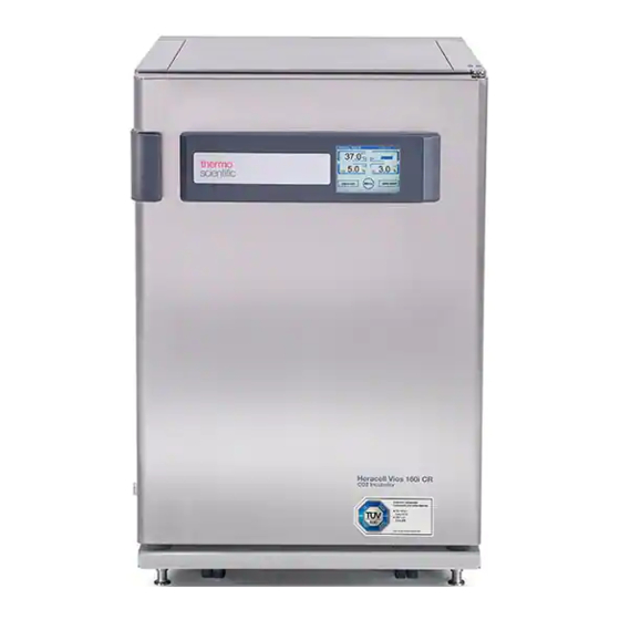
Thermo Scientific Heracell Vios 160i CR Manuals
Manuals and User Guides for Thermo Scientific Heracell Vios 160i CR. We have
2
Thermo Scientific Heracell Vios 160i CR manuals available for free PDF download: Operating Instructions Manual
Thermo Scientific Heracell Vios 160i CR Operating Instructions Manual (216 pages)
Brand:
Thermo Scientific
| Category:
Laboratory Equipment
| Size: 7 MB
Table of Contents
Table of Contents
3
General Notes
13
Identification of the Device
13
Identification of the Device and of the Documentation
13
Instruction of the Operating Personnel
13
Preface
13
Applicability of the Instructions
14
Original Document for Translation
14
Requirements for Warranty
14
Warranty
14
Explanation of Safety Information and Symbols
15
Safety Information and Symbols Used in the Operating Instructions
15
Additional Symbols for Safety Information
16
Correct Use
17
Intended Purpose of the Device
17
Symbols on the Device
17
Incorrect Use
18
Standards and Directives
18
Instruction of the Personnel
19
Safety Notes on Carbon Dioxide (CO2)
19
Safety Notes on Gases
19
Safety Notes on Nitrogen (N2)
20
Safety Notes on Oxygen (O2)
20
Chapter 1 Delivery of the Device
21
Packaging
21
Examination on Receipt
21
Standard Equipment Components Heracell Vios 160I / 250I CR
22
Optional Equipment Components Heracell Vios 160I / 250I CR
22
Optional Equipment Components Heracell Vios 160I / 250I CR
23
Chapter 2 Installation of the Device
25
Environmental Conditions
25
Requirements
25
Site Ventilation
26
Space Requirements
26
Figure 2-1. Device Dimensions
26
Transport
27
Figure 2-2. Lift Points
27
Stacking
28
Figure 2-3. Stacking
28
Figure 2-4. Stacking Adapter and Base Rack with Stacking Elements
29
Figure 2-5. Fastening the Adapter Plate to the Lower Unit
29
Figure 2-6. Removing the Screws
29
Stacking Variants
31
Installing the Support Stand with Castors
31
Figure 2-7. Support Stand with Castors Without Supporting Feet (160I Unit)
31
Support Stand with Castors and Supporting Feet (160I and 250I Unit)
32
Installing the Floor Stand, 780 MM
34
Retrofitting/Modifications
35
Chapter 3 Description of the Device
37
Heracell Vios 160I / 250I CR Front View
38
Figure 3-1. Heracell Vios 160I / 250I CR Front View
38
Heracell Vios 160I / 250I CR Back View
40
Safety Devices Heracell Vios 160I / 250I CR
40
Figure 3-2. Heracell Vios 160I / 250I CR Back View
40
Workspace Atmosphere
41
Temperature
41
Relative Humidity
41
Water Quality Recommendations
41
Prefilter
42
HEPA Filter and Air Duct
42
Figure 3-3. HEPA Filter and Airbox
43
CO2 Supply
44
O2 Supply
44
Figure 3-4. Air Duct
44
N2 Supply
45
Door Switch
46
Sensor System
46
Figure 3-5. Door Switch
46
Figure 3-7. Sensors for Water Level
47
Supply Interface
49
Standard Interfaces
49
Figure 3-8. Interfaces (Right Side of Control Box)
49
Gas Connection
50
USB Interface
50
4-20 Ma Interface
50
Alarm Contact
52
Power Supply Connection
52
Workspace Components
52
Inner Container
52
Glass Door and Optional Gas-Tight Screen
53
Figure 3-9. Heracell Vios 160I / 250I CR with Glass Door
53
Water Reservoir
54
Figure 3-10. Heracell Vios 160I CR with Threefold Gas-Tight Screen
54
Figure 3-11. Water Reservoir
55
Figure 3-12. Fill and Drain Valve of Water Reservoir
55
Water Filling
56
Heating System
56
Figure 3-13. Fill and Drain Valve Incubator
56
Figure 3-14. Refill Funnel
56
Rear Panel Openings
57
Figure 3-15. Rear Panel Openings
57
Shelf System
58
Figure 3-16. Shelf System Components
58
Electromechanical Door Lock
59
Figure 3-17. Door Lock Latch and Emergency Release on Underside of Incubator
59
Chapter 4 Start-Up
61
Adapting the Unit to the Ambient Atmosphere
61
Preparing the Workspace
61
Installing the "MAX" Fill Level Indicator and the Prefilter
62
Figure 4-1. "MAX" Fill Level Indicator
63
Figure 4-2. "MAX" Fill Level Indicator and Prefilter
63
Installing the HEPA Filter in the Rear Wall Filter Enclosure
64
Install the Air Duct
64
Figure 4-3. Assembling the Air Duct
65
Installing the HEPA Filter and the Water Reservoir Cover Panel
66
Figure 4-4. Air Duct Parts Heracell Vios 160I CR
66
Figure 4-5. Assembling the HEPA Filter and the Airbox
67
Figure 4-6. Place the Airbox Onto the Water Reservoir Cover Panel
68
Figure 4-7. Installing the Airbox
68
Installing the HEPA Filter in the Rear Panel
69
Installing the Shelf System
69
Installation/Removal of the Support Rail
69
Figure 4-8. Support Rail Installation/Removal
69
Shelf Support Installation
70
Figure 4-9. Shelf Support Installation
70
Levelling the Device
71
Mounting the Split Shelves (Optional) into the Heracell Vios 250I CR
71
Figure 4-10. Installation of Split Shelves
71
Reinforced Shelves
72
Removal of Protection Foil
72
Installing the Shelf Supports
73
Assembly of Reinforced Shelf
73
Installing the Reinforced Shelf
74
Gas Connection
74
Installing Gas Pressure Hoses
75
Figure 4-11. Installing Gas Pressure Hoses
75
Gas Connection
76
Figure 4-12. Gas Connection
76
Mains Connection
77
Figure 4-13. Mains Connection
77
Connecting the USB Interface
78
Connecting the Alarm Contact
78
Figure 4-14. Connection Example Alarm Contact
79
Connecting the 4-20 Ma Interface
80
Figure 4-15. Pin-Out of the 4-20 Ma Interface
80
Chapter 5 Operation
81
Preparing the Device
81
Starting Operation
82
Figure 5-1. Water Reservoir
82
Water Filling
83
Figure 5-2. Fill and Drain Valve Incubator
83
Figure 5-3. Refill Funnel
83
Figure 5-4. "MAX" Fill Level Indicator
84
Chapter 6 Handling and Control
87
Power Switch
88
Figure 6-1. Power Switch
88
Operating Panel and Operating Structure
89
Figure 6-2. Main Screen: Touch-Sensitive Screen Areas
89
Versions Without O2/N2 Control
90
Structure of the Operating Levels
91
Figure 6-4. Ican Touchscreen with Combined Gas Connection
91
Figure 6-5. Menu Structure Overview
92
Factory Presettings of the Ican™ Touchscreen Controls
93
Heat-Up Phase of the Control Loop Sensors
93
Figure 6-6. Heat-Up Phase Display
93
Behavior of Keys During Adjustments
94
Setting the Temperature Set Value
94
Figure 6-7. Temperature Display Field and Temperature Selection Menu
94
Setting the CO2 Set Value
95
Figure 6-8. Setting the Temperature Set Value
95
Figure 6-9. CO2 Display and CO2 Menu
95
Setting the O2 Set Value
96
Figure 6-10. Setting the CO2 Set Value
96
Figure 6-11. O2 Display and O2 Menu
97
Figure 6-12. Setting the O2 Set Value
97
Auto-Start Function
98
Activating the Auto-Start Routine
100
Figure 6-13. Activating the Auto-Start Routine
100
Interrupting the Auto-Start Routine
101
Figure 6-14. Auto-Start-Status Display Window
101
Launching Steri-Run
102
Figure 6-15. Interrupting the Auto-Start Routine
102
Figure 6-16. Error Message Subsequent to Aborted Auto-Start
102
User Configuration
103
Settings / Setup
103
Figure 6-17. User Configuration Menu
103
Figure 6-18. Settings/Setup Menu
104
Figure 6-19. Changing the Keypad Lock Code
104
Figure 6-20. Changing the Keypad Lock Code
105
Figure 6-21. Date/Time Menu
106
Figure 6-22. Setting the Date
106
Figure 6-23. Setting the Time
107
Figure 6-24. Adjusting Display Brightness
108
Figure 6-25. Adjusting Key Tone Volume
109
Figure 6-26. Interface USB Menu
110
Figure 6-27. USB Interface Baud Rate Setting
110
Figure 6-28. Language Setting
111
Figure 6-29. Choose the Desired Reminder Interval Function
112
Data Logging
113
Figure 6-30. Setting the Reminder Interval for Steri-Run
113
Figure 6-31. Event Logging Menu
114
Figure 6-32. Event Display
114
Figure 6-33. Logging Cycle Setting
115
Figure 6-34. Displaying the Error Table
116
Options
117
Figure 6-35. Options Menu
117
Figure 6-36. Alarm Menu
118
Figure 6-37. Alarm Relay Setting
118
Figure 6-38. Low Humidity Setting
119
Figure 6-39. Setting the Gas Tight Screen
120
Figure 6-40. Setting the Water Level Sensor
121
Figure 6-41. Setting the Alarm Relay
122
Figure 6-42. Switching the O2 Control on and off
123
Figure 6-43. HEPA Configuration
124
Figure 6-44. Activating / De-Activating the HEPA Filter
124
Icon Description
125
Figure 6-45. Icon Description
125
Enabling/Disabling the Keypad Lock
126
Software Versions
127
Scaling the Trend Display
127
Figure 6-46. Enabling/Disabling the Keypad Lock
127
Figure 6-47. Software Versions
127
Figure 6-48. Viewing the CO2 Concentration Graph Display
128
Figure 6-49. Viewing the CO2 Concentration Graph Display
128
Error Messages
129
Response to an Error Message Event
129
Resetting Overtemperature Protection
130
Figure 6-50. Event Error Messages
130
Figure 6-51. Failure Message Overtemperature
130
Measures after Power Outage
131
Figure 6-52. Failure Message Overtemperature
131
Troubleshooting
132
Chapter 7 Shut-Down
139
Shutting the Device down
139
Figure 7-1. Fill and Drain Valve of Water Reservoir
139
Chapter 8 Cleaning and Disinfection
141
Cleaning
141
Disinfection Procedures
142
Preparing for Sterilization / Steri-Run
142
Figure 8-1. Fill and Drain Valve of Water Reservoir
142
Wipe/Spray Disinfection of the Workspace
143
Figure 8-2. HEPA Filter and Airbox
145
Figure 8-3. Air Duct
146
Steri-Run Sterilization Routine
147
Progress of a Steri-Run Sterilization Routine
148
Figure 8-4. Steri-Run Sterilization Routine Phases
149
Activate Steri-Run
150
Figure 8-5. Steri-Run Menu - Progress
150
Canceling Steri-Run
151
Figure 8-6. Activate Steri-Run
151
Steri-Run Interruption Due to Error
152
Figure 8-7. Interrupting / Canceling Steri-Run
152
Completing Steri-Run
153
Figure 8-8. to Stop Steri-Run
153
Opening the Door after Canceling Steri-Run
154
Figure 8-9. Door Lock Latch and Emergency Release on Underside of Incubator
154
Chapter 9 Maintenance
155
Inspections and Checks
155
Service Intervals
156
Preparing Temperature Calibration
156
Temperature Calibration Procedure
157
Figure 9-1. Preparing Temperature Calibration
157
Figure 9-2. Temperature Display Field and Temperature Selection Menu
158
Figure 9-3. Temperature Calibration Procedure
158
Preparing the CO2 Calibration
159
Figure 9-4. Gas-Tight Screen Measurement Port
159
CO2 Calibration Procedure
160
Replacing the HEPA Filter in the Workspace
161
Figure 9-5. CO2 Calibration Procedure
161
Figure 9-6. Removing the Airbox
162
Figure 9-7. Installing the HEPA Filter
163
Replacing the HEPA Filter in the Rear Wall Filter Enclosure
164
Replacing the Gas Inlet Filter
164
Device Fuse Replacement
165
Replacing the Outer Door Seal
165
Figure 9-8. Gas Inlet Filter Installation
165
Spare Parts and Accessories
166
Chapter 10 Waste Disposal
167
Chapter 11 Specifications
169
Heracell Vios 160I CR
170
Heracell Vios 250I CR
174
Chapter 12 Data Communication
179
USB Interface
179
Installing the USB Port Driver
180
Structure of the Command Sequences for Data Communication
182
Description of Protocol
182
Overview of General Parameters (Addresses 0Xxx)
183
Reading General Parameters
183
Overview of Incubator Parameters (Addresses 2Xxx)
183
Reading Basic Parameters
184
Reading Internal Function Parameters
185
Error Memory Structure
186
Error Memory Data Set Structure Scheme
187
Overview of the Possible Error Messages in Hex Coding
188
Overview of the Possible Error Messages in Bit Coding General Device Status, Temperature and CO2 Control Loop
188
O2 Control Loop and Water Level
189
Data Logger Structure
189
Data Logger Data Set Structure Scheme
191
Overview of Possible Event Entries in Bit Coding Overview of Event Entries, Part I
192
Examples of Data Logger Codes
193
Functions for Data Logger Queries
194
Example of a Code for a a Data Logger Query
194
Program Heracell Vios 160I / 250I CR
199
Installing the Heracell Vios 160I CR & Heracell Vios 250I CR
200
Chapter 13 Device Log
207
Chapter 14 Contact Information Thermo Scientific
209
Appendix A Sixfold Gas Tight Screen for Cell Locker System
213
Installation of the Shelving
214
Advertisement
Thermo Scientific Heracell Vios 160i CR Operating Instructions Manual (214 pages)
CO2 Incubator
Brand:
Thermo Scientific
| Category:
Accessories
| Size: 6 MB
Advertisement
Related Products
Thermo Scientific HERACELL VIOS 160i
Thermo Scientific Lab-Line 100JPN
Thermo Scientific Lab-Line 152
Thermo Scientific Lab-Line 100-5JPN
Thermo Scientific Lab-Line 101
Thermo Scientific Lab-Line 120JPN
Thermo Scientific Lab-Line 120-5JPN
Thermo Scientific Lab-Line 121
Thermo Scientific Lab-Line 125
Thermo Scientific Lab-Line 126
Thermo Scientific Categories
Laboratory Equipment
Measuring Instruments
Freezer
Accessories
Refrigerator
More Thermo Scientific Manuals
Login
Sign In
OR
Sign in with Facebook
Sign in with Google
Upload manual
Upload from disk
Upload from URL