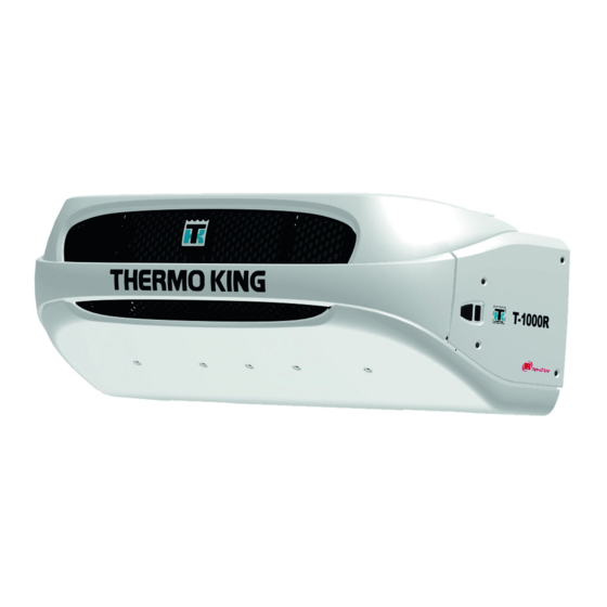
Sign In
Upload
Manuals
Brands
Thermo King Manuals
Air Conditioner
T-1000R
Thermo King T-1000R Manuals
Manuals and User Guides for Thermo King T-1000R. We have
5
Thermo King T-1000R manuals available for free PDF download: Maintenance Manual, Installation Manual, Operator's Manual, Manual
Thermo King T-1000R Maintenance Manual (282 pages)
Brand:
Thermo King
| Category:
Trucks
| Size: 8.7 MB
Table of Contents
Table of Contents
3
Introduction
7
Safety Precautions
9
3 Specifications
15
Engine
16
Belt Tension
17
Engine Clutch
18
Refrigeration System
19
Electrical Control System
20
Fuses - (Except T-500R/T-Dairy)
21
Fuses T-500R/T-Dairy
21
Electrical Components
22
Electrical Standby T-1000R/T-1200R/T-1000R Spectrum/T-1200R Spectrum
23
Electrical Standby T-600R/T-800R/T-800R Spectrum
23
Evaporator Fan Motors (UT-Series)
23
Electric Heater Strips (Optional)
24
Electrical Standby T-500R/T-Dairy
24
Electrical Standby UT-Series
24
4 Maintenance Inspection Schedule
25
Unit Models: T-Series (Except T-500R) and T-Series Spectrum Host
26
Unit Models: T-Series Spectrum
28
Unit Models: T-500R
29
Unit Models: UT-Series
31
Unit Models: UT-Series Remote Evaporators
33
5 Unit Description
35
Design Features
36
General Description
36
Engine
37
Standard HMI Control Panel
37
Unit Options
37
Mechanics HMI Control Panel
38
Premium HMI Control Panel (Optional)
38
DAS - Data Acquisition System (Optional - Except on T-500R/T-Dairy)
39
Defrost
39
Electric Standby (Model 50 Units Only)
39
Engine Compartment Components
39
Unit Protection Devices
40
Refrigeration System Components
45
Single Temperature Refrigeration System Diagrams
47
Multi-Temperature Refrigeration System Diagrams
58
6 Operating Instructions Premium Hmi
73
Controller Description
75
Controller Features
76
Display
76
Keys
76
The Premium Display
76
Operating the Unit at a Single Temperature (SPECTRUM)
77
Operating the Unit in Single Zone Control Mode (SPECTRUM)
77
If more than One Language Is Enabled
78
Turning the Unit on and off
78
Changing the Setpoint
80
Changing the Setpoint (SPECTRUM)
81
Starting the Diesel Engine
82
Starting the Electric Motor
82
Switching from Diesel to Electric (Premium HMI Only)
82
Defrost
83
Initiating a Manual Defrost Cycle
83
Switching from Electric to Diesel (Premium HMI Only)
83
Selecting High Speed Lockout Mode (if Enabled)
84
Terminating a Defrost Cycle
84
Selecting CYCLE-SENTRY or Continuous Mode
85
Using the Gauges Key
85
Using the Sensors Key
86
Using the Main Menu
87
Languages
88
Main Menu Choices
88
Alarm Types
90
Alarms
90
Check Alarms
90
Log Alarms
90
Shutdown Alarms
90
Alarm Code Notification
91
Clearing Alarm Codes
91
Prevent Alarms
91
Displaying and Clearing Alarm Codes
92
Datalogger
93
Hourmeters
93
Keypad Lockout
94
Mode
94
Turn CYCLE-SENTRY on or off
94
Selecting CYCLE-SENTRY or Continuous Mode
95
Start Sleep Mode
95
Selecting Sleep Mode
96
Pretrip
98
Pretrip Test Conditions
98
Performing a Pretrip Test
99
Diesel/Electric Menu
100
Adjust Brightness
101
Time
102
7 Operating Instructions Standard Hmi
103
Controller Description
104
Controller Features
104
Display
104
Keys and LED Indicators
105
The Multi-Temperature Display and Zone Indicators
106
The Standard Display
108
Changing the Zone Setpoint
111
Starting the Diesel Engine
112
Starting the Electric Motor
112
Switching from Electric to Diesel
112
Selecting CYCLE-SENTRY or Continuous Mode
113
Selecting the High Speed Lock-Out Feature
113
Initiating a Manual Defrost Cycle
114
Terminating a Defrost Cycle
114
Alarm Code Notification
115
Alarms
115
Clearing Alarm Codes
115
Displaying Alarm Codes
115
Important Alarm Notes
115
Sending a Servicewatch Data Logger Start of Trip
115
Pretrip Test
116
Pretrip Test Conditions
116
Pretrip Test Considerations
116
Pretrip Test Results
117
Starting a Pretrip Test
117
Checking Truck HMI Control Panel Software Revision and Serial Number
118
8 Electrical Maintenance
121
Alternator Charging System Diagnostic Procedures
122
Alternator Identification
122
General Information
122
Alternator Load Test
123
General Diagnostic and Warranty Evaluation Procedure
123
Interface Board Fuse F4
123
Test Equipment for Checking Voltage and Current
123
Battery
125
Field Current Test
125
Fuses
125
Interface Board Leds
127
Smart Fets
128
SMART REEFER 2/3 (SR-2/3) Microprocessor Controller
128
Expansion Module
129
Expansion Module (SPECTRUM Systems ONLY [T-Series SPECTRUM and UT SPECTRUM])
129
Expansion Module Leds
129
Spectrum])
129
Flywheel (RPM) Sensor
130
Glow Plugs
131
AC Components (Model 50 Units Only)
132
Electrical Contactors
132
Unit Wiring
132
Condenser Fan Rotation
133
Evaporator Heaters (Optional)
133
Phase Select Module for Truck Unit Model 50 Applications
133
Overload Relay
137
9 Engine Maintenance
139
Emi 2000
140
Engine Lubrication System
140
Engine Oil Change
140
Engine Oil Pressure Switch/Sensor
140
Crankcase Breather System
141
Engine Air Cleaner (EMI 2000)
141
Oil Filter Change
141
Engine Cooling System
143
General Description
143
Bleeding Air from the Cooling System
145
Antifreeze Maintenance Procedures
147
ELC (Extended Life Coolant)
147
Engine Thermostat
148
Coolant Level Switch
149
Engine Fuel System
150
Maintenance
150
Operation
150
Bleeding the Fuel System
151
Draining Water from Fuel Tank
157
Electric Fuel Pump
157
Fuel Filter Replacement
157
Injection Pump Timing
158
Injection Pump Removal and Installation
161
Fuel Limit Screw
163
Fuel Solenoid
163
Engine Speed Adjustments
165
Adjust Engine Valve Clearance
167
Engine Mounts
170
Belt Tensions
175
Belts
175
Water Pump Belt
177
Engine/Electric Motor (Jackshaft) Belt - T-Series
179
Engine/Electric Motor (Jackshaft) Belt - T-500R/T-Dairy
180
Compressor/Electric Motor Belt - UT-Series
182
Engine/Electric Motor Belt - UT-Series
182
Electric Motor/Alternator Belt - UT-Series
183
10 Refrigeration Maintenance
185
Evacuation, Dehydration, and Charging
187
Set up and Test of Evacuation Equipment
190
Using Evacuation Mode (Not on T-500R/T-Dairy)
190
Unit Evacuation
191
Unit Charging (T-Series)
192
Charging Procedure for T-Spectrum & UT Units
194
Refrigerant Gauge Removal
195
Checking Compressor Oil
196
Refrigerant Charge
196
Refrigerant Leaks
196
Refrigeration System Checks
197
Low Side Pump down
198
Low Side Pump down Reciprocating Compressor
198
Low Side Pump down Scroll Compressor
198
R-404A/R-452A/R-134A
198
Refrigeration System Component Locations
200
Accumulator Replacement
206
Compressor Oil Filter
207
Reciprocating Compressor Replacement (T-Series)
207
Checking Compressor Oil Pressure
208
Priming New Compressor Installations
209
TKO Scroll Compressor (UT-Series)
209
Scroll Compressor Shaft Seal Replacement
210
Scroll Compressor Oil Filter Replacement
211
Scroll Compressor Oil Replacement
211
Scroll Compressor High Temperature Switch Replacement
212
Scroll Compressor Liquid Injection Fitting Replacement
212
Condenser Check Valve and Purge Check Valve Test (T-500R/T-Dairy)
213
Condenser Check Valve Test (Single Temperature Units Only)
213
Condenser Check Valve, Purge Check Valve, and Receiver Tank Pressure Solenoid Leak Test (Multi-Temp Units Only)
214
Condenser Inlet Solenoid (CIS) Test
215
Condenser/Radiator Coil Replacement
215
Dehydrator (Filter-Drier) Replacement
216
Discharge Pressure Regulator (DPR) Replacement
216
Discharge Pressure Regulator (DPR) Test
216
Discharge Pressure Transducer Replacement
217
Discharge Pressure Transducer Testing
217
Discharge Strainer Test
217
Discharge Strainer Replacement
218
Electronic Throttling Valve (ETV) Replacement
218
Electronic Throttling Valve (ETV) Testing
218
Evaporator Coil Replacement
223
Expansion Valve Replacement
223
Heat Exchanger Replacement
224
High Pressure Cutout Switch (HPCO) Replacement
225
High Pressure Cutout Switch (HPCO) Test
225
High Pressure Relief Valve Replacement
226
Hot Gas Bypass Solenoid (HGBS) Test
226
Hot Gas Solenoid (HGS) Test
227
In-Line Check Valve Replacement
227
Liquid Injection Solenoid (LIS) Replacement
228
Liquid Injection Solenoid (LIS) Test
228
(Multi-Temp Units Only)
229
Liquid Line Solenoid (LLS) and Liquid Return Check Valve Test
229
Liquid Line Solenoid (LLS) and Liquid Return Check Valve Test (Multi-Temp Units Only)
229
Low Pressure Cutout Switch (LPCO) Replacement
229
Low Pressure Cutout Switch (LPCO) Test (T-500R/T-Dairy Only)
229
Purge Valve (PV) Test
230
Receiver Tank Pressure Check Valve Test
230
Receiver Tank Pressure Solenoid (RTPS) Test (Multi-Temp Units Only)
230
Receiver Tank Replacement
231
Solenoid Valve Replacement
231
Suction Line Check Valve Test (Multi-Temp Units Only)
232
Suction Line Solenoid (SLS) Test (Multi-Temp Units Only)
232
Suction Pressure Regulator (SPR) Replacement
233
Suction Pressure Regulator (SPR) Test
233
Suction Pressure Transducer Replacement
234
Suction Pressure Transducer Testing
234
Suction Pressure Transducer Testing (UT-Series and T-Series Except T-500R/T-Dairy)
234
T-500R/T-Dairy)
234
Throttling Valve Replacement and Repair
234
Throttling Valve Test
234
11 Clutch Maintenance
239
Centrifugal Clutch
240
Clutch Maintenance
242
12 Structural Maintenance
247
Condenser, Evaporator and Radiator Coils
248
Micro-Channel Coil Cleaning Recommendations
248
Unit and Engine Mounting Bolts
248
Unit Inspection
248
Defrost Damper
250
Defrost Drains (UT-Series)
250
Fan Location
250
Fanshaft Assembly
251
Disassembly
252
Reassembly
254
13 Mechanical Diagnosis
259
14 Electric Standby Diagnosis
265
Refrigeration System Diagnosis
269
Unit Description
274
Electrical Maintenance
279
Remote Evaporator System Diagnosis
279
Structural Maintenance
279
Wiring Diagrams and Wiring Schematics
281
Advertisement
Thermo King T-1000R Maintenance Manual (175 pages)
Brand:
Thermo King
| Category:
Automobile Accessories
| Size: 7.15 MB
Table of Contents
Table of Contents
6
Safety Precautions
11
General Practices
11
Auto Start/Stop
12
Battery Installation and Cable Routing
12
Battery Removal
12
Refrigerant Hazards
12
Refrigerant Oil Hazards
13
Electrical Hazards
13
High Voltage
13
Low Voltage
14
Microprocessor Service Precautions
14
Welding Precautions
14
First Aid
15
First Aid, Refrigerant
15
First Aid, Refrigerant Oil
15
First Aid, Engine Coolant
15
First Aid, Electrical Shock
15
Specifications
16
Engine
16
Belt Tension
17
Engine Clutch - Hilliard
17
Refrigeration System
17
Electrical Control System
18
Fuses
18
Electrical Components
18
Electrical Standby (Model 50 Units Only)
19
T-600R and T-800R Electric Motor and Overload Relay
19
T-1000R Electric Motor and Overload Relay
19
Electric Heater Strips (Optional)
19
Standby Power Requirements
19
Unit Description
22
General Description
22
Design Features
22
Unit Options
23
Engine
23
ELC (Extended Life Coolant)
23
Clutch
23
Reciprocating Compressor
23
Standard HMI Control Panel
23
Mechanics HMI Control Panel
24
Premium HMI Control Panel (Optional)
24
CYCLE-SENTRYTM Start/Stop System
24
Defrost
24
DAS - Data Acquisition System (Optional)
25
Electric Standby (Model 50 Units Only)
25
Standard Model 50 Features
25
Optional Model 50 Features
25
Engine Compartment Components
25
Unit Protection Devices
25
Refrigeration System Components
28
Solenoids and Valves
28
Sensors, Switches, and Transducers
28
Refrigeration System Diagrams
29
Cool Mode
30
Purge Mode
31
Heat/Defrost Mode
32
Operating Instructions for Standard HMI Control Panel
33
Truck HMI Controller Description
33
SR-2 Truck HMI Controller
33
Display
33
Keys and LED Indicators
35
Turning the Unit on and off
37
The Standard Display
37
Changing the Setpoint
38
Starting the Diesel Engine
38
Starting the Electric Motor
39
Switching from Diesel to Electric
39
Switching from Electric to Diesel
39
Selecting CYCLE-SENTRY or Continuous Mode
40
Selecting the High Speed Lock-Out Feature
41
Initiating a Manual Defrost Cycle
41
Alarms
42
Sending a Servicewatch Data Logger Start of Trip
43
Pretrip Test
43
Pretrip Test Conditions
43
Conditions Where Pretrip Tests Are Not Allowed
43
Pretrip Test Sequence
43
Pretrip Test Considerations
44
Performing a Pretrip Test
44
Starting a Pretrip Test
44
Pretrip Test Results
45
Display Brightness
45
Checking Truck HMI Control Panel Software Revision and Serial Number
46
Operating Instructions for Premium HMI Control Panel
47
Truck Premium HMI Controller Description
47
Premium HMI Control Panel
47
Display
47
Keys
48
Hard Keys
48
Soft Keys
48
Turning the Unit on and off
48
If more than One Language Is Enabled
49
The Standard Display
50
Changing the Setpoint
50
Starting the Diesel Engine
51
Starting the Electric Motor
52
Switching from Diesel to Electric
52
Switching from Electric to Diesel
53
Initiating a Manual Defrost Cycle
53
Terminating a Defrost Cycle
54
Selecting High Speed Lockout Mode (if Enabled)
54
Selecting CYCLE-SENTRY or Continuous Mode
54
Using the Gauges Key
54
Using the Sensors Key
55
Using the Main Menu
56
Main Menu Choices
56
Languages
57
Alarms
58
Datalogger
62
Hourmeters
62
Mode
63
Selecting CYCLE-SENTRY or Continuous Mode
64
Selecting Sleep Mode
65
Pretrip
67
Diesel/Electric Menu
69
Adjust Brightness
70
Time
71
Electrical Maintenance
72
Alternator Charging System Diagnostic Procedures
72
General Information
72
Alternator Identification
72
Interface Board Fuse F4
73
Test Equipment for Checking Voltage and Current
73
Alternator Load Test
73
General Diagnostic and Warranty Evaluation Procedure
73
Field Current Test
75
Battery
75
Fuses
76
Interface Board Leds
77
Smart Fets
77
SMART REEFER 2 (SR-2) Microprocessor Controller
77
Flywheel (RPM) Sensor
77
Glow Plugs
78
Unit Wiring
79
AC Components (Model 50 Units Only)
79
Electrical Contactors
79
Evaporator Heaters (Optional)
79
Condenser Fan Rotation
79
Phase Select Module for Truck Unit Model 50 Applications
79
Overload Relay
82
Engine Maintenance
84
Emi 2000
84
Engine Lubrication System
84
Engine Oil Pressure Switch/Sensor
84
Engine Oil Change
84
Oil Filter Change
85
Engine Air Cleaner (EMI 2000)
85
Crankcase Breather System
86
Engine Cooling System
87
General Description
87
ELC (Extended Life Coolant)
89
Antifreeze Maintenance Procedures
89
Bleeding Air from the Cooling System
90
Engine Thermostat
91
Coolant Level Switch
92
Engine Fuel System
92
Operation
92
Maintenance
93
Bleeding the Fuel System
93
Draining Water from Fuel Tank
96
Fuel Filter Replacement
96
Electric Fuel Pump
96
Injection Pump Timing
97
Injection Pump Removal and Installation
99
Fuel Limit Screw
101
Fuel Solenoid
101
Engine Speed Adjustments
103
Adjust Engine Valve Clearance
104
Engine Mounts
107
Restraining Mount (Snubber) Adjustment
108
Belts
109
Engine/Electric Motor (Jackshaft) Belt
110
Electric Motor (Jackshaft)/ Compressor Belt
112
Water Pump Belt
114
Refrigeration Service Procedures
115
Evacuation, Dehydration, and Charging
115
Set up and Test of Evacuation Equipment
118
Unit Evacuation
118
Unit Charging
120
Refrigerant Gauge Removal
120
Refrigerant Leaks
120
Refrigerant Charge
120
Testing the Refrigerant Charge with an Empty Box (Controlled Check)
120
Testing the Refrigerant Charge with a Loaded Box (Quick Check)
121
Checking Compressor Oil
121
Refrigeration System Checks
122
Low Side Pump down
122
R404A
123
Unit Identification
123
Availability
123
Leak Detection
123
Compressor Oil
123
Compressors Shipped with POE Oil
123
Equipment Recommendations for Use with R404A
123
Refrigerant Recovery
124
Refrigeration System Component Locations
124
Accumulator Replacement
128
Removal
128
Installation
128
Compressor Test
128
Compressor Replacement
128
Installation
129
Compressor Oil Filter
129
Checking Compressor Oil Pressure
131
Priming New Compressor Installations
131
Condenser Check Valve and Purge Check Valve Test
132
Condenser Inlet Solenoid (CIS) Test
133
Condenser/Radiator Coil Replacement
133
Removal
133
Installation
134
Dehydrator (Filter-Drier) Replacement
134
Removal
134
Discharge Strainer Test
135
Discharge Strainer Replacement
135
Removal
135
Installation
135
Evaporator Coil Replacement
135
Expansion Valve Replacement
136
Removal
136
Installation
136
Heat Exchanger Replacement
136
Installation
137
High Pressure Cutout Switch (HPCO) Test
137
High Pressure Cutout Switch (HPCO) Replacement
138
Removal
138
Installation
138
High Pressure Relief Valve Replacement
138
Hot Gas Solenoid (HGS) Test
138
In-Line Check Valve Replacement
139
Removal
139
Installation
139
Purge Valve (PV) Test
139
Receiver Tank Pressure Check Valve Test
140
Receiver Tank Replacement
140
Removal
140
Installation
140
Solenoid Valve Replacement
140
Installation
141
Suction Pressure Regulator (SPR) Test
141
Suction Pressure Regulator (SPR) Replacement
141
Removal
141
Suction Pressure Transducer Testing
141
Suction Pressure Transducer Replacement
141
Installation
142
Clutch Maintenance
143
Centrifugal Clutch
143
Clutch Maintenance
145
Tools Required
145
Grease
145
Disassembly Procedure
145
Assembly Procedure (Using New Bearings and Seal)
146
Structural Maintenance
148
Unit and Engine Mounting Bolts
148
Unit Inspection
148
Condenser, Evaporator and Radiator Coils
148
Micro-Channel Coil Cleaning Recommendations
148
Fan Location
149
Plastic Defrost Damper
150
Fanshaft Assembly
151
Disassembly
151
Reassembly
153
Jackshaft Assembly
154
Disassembly
154
Reassembly
155
Mechanical Diagnosis
156
Electric Standby (Optional) Diagnosis
160
Refrigeration Diagnosis
162
Index
164
Wiring and Schematic Diagrams Index
166
Thermo King T-1000R Operator's Manual (68 pages)
Brand:
Thermo King
| Category:
Refrigerator
| Size: 1.58 MB
Table of Contents
Table of Contents
3
Introduction
5
General Information
5
Thermo Assistance
5
First Aid and Safety
6
Refrigerant Information
6
Safety Precautions
6
Unit Description
8
General Description
8
Design Features
8
Unit Options
9
Engine
9
ELC (Extended Life Coolant)
9
Clutch
9
Reciprocating Compressor
9
HMI Control Panel
9
CYCLE-SENTRYTM System
10
Defrost
11
DAS - Data Acquisition System
11
Engine Compartment Components
11
Electric Standby (Model 50 Units Only)
12
Unit Protection Devices
12
Unit Operating Instructions Standard TSR/TSR-3 HMI
16
Controller
16
The Multi-Temperature Display and Zone Indicators
20
Starting the Diesel Engine
21
Starting the Electric Motor
21
Alarms
21
Pretrip Test
22
Display Brightness
23
Checking Truck HMI Control Panel Software Revision
23
And Serial Number
23
Keypad Lockout
24
Unit Operating Instructions Premium HMI Controller
25
Keys
26
Turning the Unit on and off
27
The Standard Display
28
Operating the Unit in Single Zone Control Mode (SPECTRUM)
29
Starting the Diesel Engine
30
Starting the Electric Motor
30
Main Menu Overview (Spectrum)
31
Using the Main Menu
31
Alarms
32
Datalogger
36
Hourmeters
36
Mode
37
Selecting CYCLE-SENTRY or Continuous Mode
38
Selecting Sleep Mode
40
Pretrip
42
Diesel/Electric Menu
44
Adjust Brightness
45
Time
46
TSR/TSR-3 Alarm Codes
47
Electric Standby Operation
53
Electric Power Receptacle
53
Care and Maintenance
54
Pre-Trip Inspection
54
After Start Inspection
54
Loading
55
Warranty
58
Specifications
60
Engine
60
Engine Clutch - Hilliard
62
Refrigeration System
63
Electrical Control System
63
Electric Heater Strips (Optional)
64
Standby Power Requirements
64
Fuses
65
Electrical Components
66
Serial Number and Refrigerant Label Locations
68
Advertisement
Thermo King T-1000R Installation Manual (70 pages)
Truck Edition (TSA, EMEIA and AP) Single Temperature Systems
Brand:
Thermo King
| Category:
Air Conditioner
| Size: 2.73 MB
Table of Contents
Installation Manual
1
Table of Contents
7
Safety Precautions
8
Unit Dimensions T-580R, T-600R, T-680R, T-680R, T-680S, T-800M, T-800R, T-880R, T-880S
10
Unit Dimensions T-1000M, T-1000R, T-1080R, T-1080S and T-1200R
11
Service Area - T-580R, T-600R T-680R, T-680R, T-680S, T-800M, T-800R, T-880R, T-880S
12
Service Area - T-1000M, T-1000R, T-1080R, T-1080S and T-1200R
13
Remote Power Receptacle Dimensions (OPTION)
14
Battery Box Dimensions (OPTION)
15
Remote Status Light Dimensions (OPTION)
16
HMI Controller Dimensions
17
Truck Body Opening Dimensions
18
Unit Weights
20
Lifting Bar Details
21
Required Tools
24
Installation Components
26
Uncrating the Unit
28
Installing the Unit
30
Installing the Hose Management Caps
32
Installing the Hose Management System (OPTION)
34
Securing the Oil Drain Hose
36
Securing the Evaporator Drain Hoses
38
Installing the Fuel Pickup Tube into a Steel or Aluminum Tank
40
Installing the Fuel Pickup Tube into a Plastic Tank
42
Installing the Steel Fuel Tank
44
Installing the Aluminum Fuel Tank (OPTION)
46
Installing the Fuel Pump and Fuel Lines
48
Installing the Servicewatch™ Remote Download Port (OPTION)
50
Installing the Remote Power Receptacle (OPTION)
52
Installing the Remote Status Light (OPTION)
54
Installing the HMI Controller
56
Installing the Battery Box (OPTION)
58
Battery Connections
60
Installing the Door Switch (OPTION)
62
Auxiliary Electrical Accessories
66
Unit Check List
67
Thermo King T-1000R Manual (57 pages)
Brand:
Thermo King
| Category:
Refrigerator
| Size: 2.19 MB
Table of Contents
Table of Contents
3
Introduction
7
Safety Precautions
10
General Safety Practices
10
Automatic Start/Stop Operation
10
Battery Installation and Cable Routing
11
Refrigerant
12
Refrigerant Oil
12
First Aid
13
Safety Decals and Locations
13
Refrigerant
15
Do Not Use Ether Starting Aids
16
Unit Description
17
General Information
17
Diesel Engine
17
ELC (Extended Life Coolant)
18
Clutch
18
Thermo King Reciprocating Compressor
18
Electronic Throttling Valve
19
HMI Control Panel
19
Premium
20
CYCLE-SENTRYTM Start-Stop Controls
21
The CYCLE-SENTRY
21
Telematics as Standard
21
Defrost
22
DAS - Data Acquisition System
22
Electric Standby
22
Engine Compartment Components
24
Unit Protection Devices
24
Manual Pretrip Inspection
29
Operating Instructions
32
Unit Operating Instructions Premium HMI Controller
32
Operating the TSR-3 Controller
35
Alarm Codes
36
Introduction
36
Loading and Enroute Inspections
38
Pre-Loading Inspection
38
Post-Loading Inspection
40
Specifications
45
Engine
45
Fuses
48
Electrical Control System
50
Electric Heater Strips
50
Refrigeration System
51
Warranty
53
Maintenance Inspection Schedule
54
Inspection and Service Intervals
54
Serial Number Locations
56
Recover Refrigerant
57
Advertisement
Related Products
Thermo King T-1080S
Thermo King T-1000M
Thermo King T-1080R
Thermo King T-1200R
Thermo King T-580R
Thermo King T-680S
Thermo King T-880R
Thermo King TriPac
Thermo King T-800R
Thermo King T-680R
Thermo King Categories
Refrigerator
Automobile Accessories
Air Conditioner
Heat Pump
Computer Hardware
More Thermo King Manuals
Login
Sign In
OR
Sign in with Facebook
Sign in with Google
Upload manual
Upload from disk
Upload from URL