Sign In
Upload
Manuals
Brands
Texas Instruments Manuals
Controller
UCD90320
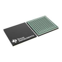
User Manuals: Texas Instruments UCD90320 System
Manuals and User Guides for Texas Instruments UCD90320 System. We have
2
Texas Instruments UCD90320 System manuals available for free PDF download: User Manual
Texas Instruments UCD90320 User Manual (91 pages)
Sequencer and System Health Controller PMBus Command Reference
Brand:
Texas Instruments
| Category:
Controller
| Size: 0 MB
Table of Contents
Table of Contents
1
Pmbus Specification
5
Pmbus Status Supported by the UCD90320
6
Manufacturer Specific Status (STATUS_MFR_SPECIFIC)
7
Data Formats
7
Data Format for Output Voltage Parameters
7
Data Format for Other Parameters
7
Distinguishing between Linear Data Formats
8
Translation, Quantization, and Truncation
8
8-Bit Time Encoding
8
Memory Model
9
Alert Response Address Support
9
Supported Pmbus Commands
10
Pmbus Commands
11
Implementation Details for Pmbus Core Commands
19
00H) PAGE
19
01H) OPERATION
19
11H) STORE_DEFAULT_ALL
19
Relationship between PAGE and Rail
19
12H) RESTORE_DEFAULT_ALL
20
1Bh) SMBALERT_MASK
20
20H) VOUT_MODE
20
38H) IOUT_CAL_GAIN
21
41H - 69H) Xxx_Fault_Response
21
Exponent Influence on Voltage Range and Resolution
21
Example Settings for Voltage Monitoring Ranges
21
62H) TON_MAX_FAULT_LIMIT
22
66H) TOFF_MAX_WARN_LIMIT
22
80H) STATUS_MFR_SPECIFIC
22
6.12 (81H) STATUS_FAN_1_2 and (82H) STATUS_FAN_3_4
22
Replaced Fault Response Commands
22
STATUS_FAN_1_2 Support
22
STATUS_FAN_3_4 Support
22
6.13 (8Dh) READ_TEMPERATURE_1
23
6.14 (8Eh) READ_TEMPERATURE_2
23
STATUS_FAN_1_2 Support with more than Four Fans
23
STATUS_FAN_3_4 Support with more than Four Fans
23
90-93H) FAN_SPEED_1 through FAN_SPEED_4
24
6.16 (Adh) IC_DEVICE_ID
24
6.17 (Aeh) IC_DEVICE_REV
24
Input and Output Pin Configuration
25
UCD90320 Pin ID Definitions
25
PWM Configuration
28
PWM-Supported Frequencies
28
Implementation Details for User Data Commands
29
B5H) BLACK_BOX_FAULT_INFO (USER_DATA_05)
29
BLACK_BOX_FAULT_INFO Command Format
29
B6H) BLACK_BOX_FAULT_RAILS_WARNING(USER_DATA_06)
30
Fault Info Format
30
BLACK_BOX_FAULT_WARNING Command Format
30
B7H) BLACK_BOX_LOG_RAILS_VALUE(USER_DATA_07)
31
B8H) RAIL_PROFILE(USER_DATA_08)
31
BLACK_BOX_FAULT_WARNING Command Format
31
Rail N Value
31
RAIL_PROFILE Command Format (Write)
31
RAIL_PROFILE Command Format (Read)
32
Number Profile (Write)
32
B9H) RAIL_STATE (USER_DATA_09)
33
RAIL_STATE Command Format
33
Rail State
33
Implementation Details for Manufacturer-Specific Commands
34
D0H) FAULT_PIN_CONFIG (MFR_SPECIFIC_00)
34
FAULT_PIN_CONFIG Command Format
34
D1H) VOUT_CAL_MONITOR (MFR_SPECIFIC_01)
35
D2H) SYSTEM_RESET_CONFIG (MFR_SPECIFIC_02)
36
SYSTEM_RESET_CONFIG Command Format
36
D3H) SYSTEM_WATCHDOG_CONFIG (MFR_SPECIFIC_03)
38
GPI Tracking Configuration
38
SYSTEM_WATCHDOG_CONFIG Command Format
38
D4H) SYSTEM_WATCHDOG_RESET (MFR_SPECIFIC_04)
40
D5H) MONITOR_CONFIG (MFR_SPECIFIC_05)
40
Reset Period Configuration for UCD90320
40
Monitor Types
40
MONITOR_CONFIG Command Format
41
Monitor Type and
42
ADC Monitor Pin Definitions
42
D6H) NUM_PAGES (MFR_SPECIFIC_06)
43
D7H) RUN_TIME_CLOCK (MFR_SPECIFIC_07)
43
D8H) RUN_TIME_CLOCK_TRIM (MFR_SPECIFIC_08)
43
D9H) ROM_MODE (MFR_SPECIFIC_09)
43
RUN_TIME_CLOCK Command Format
43
Dah) USER_RAM_00 (MFR_SPECIFIC_10)
44
Dbh) SOFT_RESET (MFR_SPECIFIC_11)
44
Dch) RESET_COUNT (MFR_SPECIFIC_12)
44
Ddh) PIN_SELECTED_RAIL_STATES (MFR_SPECIFIC_13)
44
Changes to the OPERATION Command
44
GPI Selection of System States
45
PIN_SELECTED_RAIL_STATES Command Format
45
Deh) RESEQUENCE (MFR_SPECIFIC_14)
47
Dfh) CONSTANTS (MFR_SPECIFIC_15)
47
RESEQUENCE Command Format
47
CONSTANTS Command Format
47
E0H) PWM_SELECT (MFR_SPECIFIC_16)
48
E1H) PWM_CONFIG (MFR_SPECIFIC_17)
48
E2H) PARM_INFO (MFR_SPECIFIC_18)
48
CONSTANTS for each Device
48
Valid PWM Pin Ids
48
PWM_CONFIG Command Format
48
E3H) PARM_VALUE (MFR_SPECIFIC_19)
49
E4H) TEMPERATURE_CAL_GAIN (MFR_SPECIFIC_20)
49
E5H) TEMPERATURE_CAL_OFFSET (MFR_SPECIFIC_21)
49
E9H) FAULT_RESPONSES (MFR_SPECIFIC_25)
49
PARM_INFO Command Format
49
FAULT_RESPONSES Command Format
50
Fault Response Byte Format
50
Eah) LOGGED_FAULTS (MFR_SPECIFIC_26)
52
LOGGED_FAULTS Command Format
52
Non-Paged Fault Log Bit Definitions
52
GPI Fault Log Bit Definitions
53
Ebh) LOGGED_FAULT_DETAIL_INDEX (MFR_SPECIFIC_27)
54
Ech) LOGGED_FAULT_DETAIL (MFR_SPECIFIC_28)
54
Page-Dependent Fault Log Bit Definitions
54
LOGGED_FAULT_DETAIL_INDEX Command Format
54
LOGGED_FAULT_DETAIL Command Format
55
Number of Log Entries in each Device Type
55
Edh) LOGGED_PAGE_PEAKS (MFR_SPECIFIC_29)
56
Fault Identification + Days
56
Fault Value
56
Eeh) LOGGED_COMMON_PEAKS (MFR_SPECIFIC_30)
57
Efh) LOGGED_FAULT_DETAIL_ENABLES (MFR_SPECIFIC_31)
57
LOGGED_PAGE_PEAKS Command Format
57
LOGGED_FAULT_DETAIL_ENABLES Command Format
57
F0H) EXECUTE_FLASH (MFR_SPECIFIC_32)
58
F1H) SECURITY (MFR_SPECIFIC_33)
58
F2H) SECURITY_BIT_MASK (MFR_SPECIFIC_34)
59
F3H) MFR_STATUS (MFR_SPECIFIC_35)
59
Manufacturer Specific Status
59
F4H) GPI_FAULT_RESPONSES (MFR_SPECIFIC_36)
61
GPI_FAULT_RESPONSES Command Format
61
Rail Profile Pin Selection
62
F5H) MARGIN_CONFIG (MFR_SPECIFIC_37)
63
F6H) SEQ_CONFIG (MFR_SPECIFIC_38)
63
MARGIN_CONFIG Command Format
63
SEQ_CONFIG Command Format
64
Sequencing Timeout Configuration Byte
66
F7H) GPO_CONFIG_INDEX (MFR_SPECIFIC_39)
68
F8H) GPO_CONFIG (MFR_SPECIFIC_40)
69
Relationship between GPO_CONFIG_INDEX and the Actual GPO Number
69
Factors Determining the State of a GPO
70
GPO_CONFIG Command Format
70
Ignore Inputs on
72
Ignore Inputs off
73
Ignore Inputs on with Delay
73
State Machine
74
Example of State Machine
74
Status Types
76
F9H) GPI_CONFIG (MFR_SPECIFIC_41)
80
GPI_CONFIG Command Format
80
GPI Pin Configuration
80
Fault Enable Bits
81
GPI Selection
81
Fah) GPIO_SELECT (MFR_SPECIFIC_42)
83
Fbh) GPIO_CONFIG (MFR_SPECIFIC_43)
83
Fch) MISC_CONFIG (MFR_SPECIFIC_44)
83
MISC_CONFIG Command Format
83
Fdh) DEVICE_ID (MFR_SPECIFIC_45)
84
Miscellaneous Configuration Byte
84
Range Checking and Limits
85
Range and Limits for Pmbus Commands
85
Glossary
90
Advertisement
Texas Instruments UCD90320 User Manual (5 pages)
Sequencer Schematics Guidelines
Brand:
Texas Instruments
| Category:
Recording Equipment
| Size: 0 MB
Table of Contents
Introduction
1
UCD90240, UCD90320 and UCD90320U
1
UCD Power Supply Review
2
Remaining Ucd90Xxx Devices
2
Analog Monitor (Monx/Amonx) Pin Review
2
PMBUS Signals Review
2
I/O Signals Review
3
GPIO Pins Review
3
Margin Pins Review
3
Trademarks
3
Revision History
4
Important Notice
5
Advertisement
Related Products
Texas Instruments UCC38500EVM
Texas Instruments UCC14240EVM-052
Texas Instruments UCD9224EVM-464
Texas Instruments UCD90120
Texas Instruments UCD90124
Texas Instruments UCD9080EVM
Texas Instruments UCD9081
Texas Instruments UCD90240EVM-704
Texas Instruments UCD90120EVM
Texas Instruments UCD90124EVM
Texas Instruments Categories
Motherboard
Control Unit
Microcontrollers
Computer Hardware
Calculator
More Texas Instruments Manuals
Login
Sign In
OR
Sign in with Facebook
Sign in with Google
Upload manual
Upload from disk
Upload from URL