Sign In
Upload
Manuals
Brands
Texas Instruments Manuals
Motherboard
TPS54KC23EVM
Texas Instruments TPS54KC23EVM Manuals
Manuals and User Guides for Texas Instruments TPS54KC23EVM. We have
1
Texas Instruments TPS54KC23EVM manual available for free PDF download: User Manual
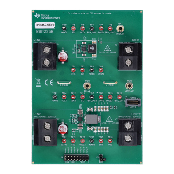
Texas Instruments TPS54KC23EVM User Manual (26 pages)
Step-Down Converter Evaluation Module
Brand:
Texas Instruments
| Category:
Motherboard
| Size: 1 MB
Table of Contents
Table of Contents
1
Introduction
3
Background
3
Before You Begin
3
Table 1-1. Input Voltage and Output Current
3
Performance Characteristics Summary
4
Table 1-2. TPS54KC23EVM Small Size (U1) Performance Characteristics Summary
4
Table 1-3. TPS54KC23EVM High Efficiency (U2) Performance Characteristics
4
Configurations and Modifications
5
Output Voltage
5
Frequency and Operation Mode Setting (MSEL Pin)
5
Table 2-1. MSEL Pin Selection
5
Test Setup and Results
6
Figure 3-1. TPS54KC23EVM
6
Input/Output Connections
7
Table 3-1. Connectors and Jumpers
7
Table 3-2. Test Points
7
Efficiency
9
Figure 3-2. U1 Efficiency - Skip-Mode (Default)
9
Figure 3-3. U2 Efficiency - Skip-Mode (Default)
9
Figure 3-4. U2 Efficiency - FCCM Vs Skip-Mode
9
Figure 3-5. U2 Efficiency - FCCM
9
Table 3-3. Efficiency Measurement Test Points
9
Output Voltage Regulation
10
Figure 3-6. U1 Load Regulation
10
Figure 3-7. U1 Line Regulation
10
Figure 3-8. U2 Load Regulation
10
Figure 3-9. U2 Line Regulation
10
Load Transient and Loop Response
11
Figure 3-10. U1 Transient Response
11
Figure 3-11. U2 Transient Response
11
Figure 3-12. U1 Bode Plot - 15-A Load
11
Figure 3-13. U2 Bode Plot - 15-A Load
11
Output Voltage Ripple
12
Figure 3-14. U1 Output Ripple - 10-Ma Load, Skip-Mode
12
Figure 3-15. U1 Output Ripple - 30-A Load
12
Figure 3-16. U2 Output Ripple - 10-Ma Load, Skip-Mode
12
Figure 3-17. U2 Output Ripple - 30-A Load
12
Start-Up and Shutdown with en
13
Thermal Performance
13
Figure 3-18. U2 Start-Up with en - 30-A Load
13
Figure 3-19. U2 Shutdown with en - 30-A Load
13
Figure 3-20. U1 Thermal Performance - 30-A Load and U2 off
13
Figure 3-21. U2 Thermal Performance - 30-A Load and U1 off
13
Board Layout
14
Layout
14
Figure 4-1. Top-Side Composite View
14
Figure 4-2. Bottom-Side Composite View (Viewed from Bottom)
14
Figure 4-3. Top Layer Layout
15
Figure 4-4. MID Layer 1 Layout
15
Figure 4-5. MID Layer
15
Figure 4-6. MID Layer
15
Figure 4-7. MID Layer
16
Figure 4-8. Bottom Layer Layout
16
Schematic and Bill of Materials
17
Schematic
17
Figure 5-1. U1 Schematic
17
Figure 5-2. U2 Schematic
18
Bill of Materials
19
Table 5-1. TPS54KC23EVM Bill of Materials
19
Advertisement
Advertisement
Related Products
Texas Instruments TPS54218EVM-511 2-A
Texas Instruments TPS54110EVM-044
Texas Instruments TPS54973EVM-017
Texas Instruments TPS549D22EVM-784
Texas Instruments TPS54A20EVM-770
Texas Instruments TPS54225EVM-538
Texas Instruments TPS54240EVM-VSON
Texas Instruments TPS54202HEVM-716
Texas Instruments SWIFT TPS54880EVM-228
Texas Instruments TPS54672
Texas Instruments Categories
Motherboard
Control Unit
Microcontrollers
Computer Hardware
Calculator
More Texas Instruments Manuals
Login
Sign In
OR
Sign in with Facebook
Sign in with Google
Upload manual
Upload from disk
Upload from URL