Sign In
Upload
Manuals
Brands
Texas Instruments Manuals
Motherboard
LMK04816
Texas Instruments LMK04816 Manuals
Manuals and User Guides for Texas Instruments LMK04816. We have
1
Texas Instruments LMK04816 manual available for free PDF download: Operating Instructions Manual
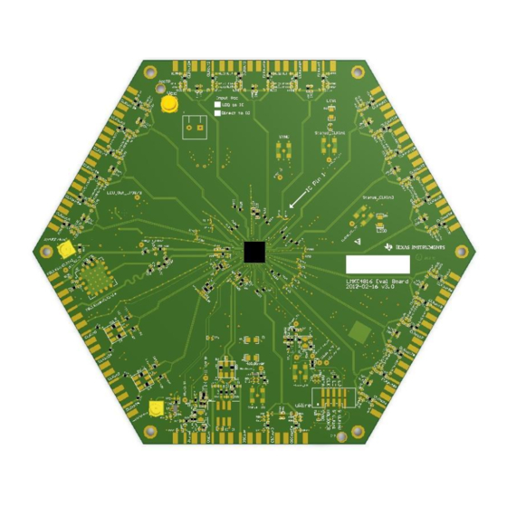
Texas Instruments LMK04816 Operating Instructions Manual (77 pages)
Low-Noise Clock Jitter Cleaner with Dual Loop PLLs Evaluation Board
Brand:
Texas Instruments
| Category:
Motherboard
| Size: 2.4 MB
Table of Contents
Table of Contents
2
General Description
4
Evaluation Board Kit Contents
4
Available Lmk04816 Evaluation Boards
4
Available Lmk04816 Family Devices
4
Quick Start
5
Default Codeloader Modes for Evaluation Boards
6
Example: Using Codeloader to Program the Lmk04816
7
Start Codeloader 4 Application
7
Select Device
7
Program/Load Device
8
Restoring a Default Mode
8
Visual Confirmation of Frequency Lock
9
Enable Clock Outputs
9
Pll Loop Filters and Loop Parameters
11
Pll 1 Loop Filter
11
122.88 Mhz VCXO PLL
11
Pll2 Loop Filter
12
Evaluation Board Inputs and Outputs
13
Recommended Test Equipment
21
Programming 0-Delay Mode in Codeloader
22
Overview
22
Dual Loop 0-Delay Mode Examples
22
Programming Steps
22
Details
22
Single Loop 0-Delay Mode Examples
24
Programming Steps
24
Details
24
Appendix A: Codeloader Usage
26
Port Setup Tab
26
Clock Outputs Tab
27
Pll1 Tab
29
Setting the PLL1 VCO Frequency and PLL2 Reference Frequency
30
Pll2 Tab
31
Bits/Pins Tab
32
Registers Tab
37
Appendix B: Typical Phase Noise Performance Plots
38
Pll1
38
122.88 Mhz VCXO Phase Noise
38
Clock Output Measurement Technique
39
Buffered Phase Noise
39
Clock Outputs (Clkout)
40
LMK04816B Clkout Phase Noise
40
LMK04816B Oscout Phase Noise
41
Appendix C: Schematics
43
Power Supplies
43
Lmk04816B Device with Loop Filter and Crystal Circuits
44
Reference Inputs (Clkin0, Clkin1, & Clkin2), External VCXO (Oscin) & VCO Circuits
45
Clock Outputs (Osc out 0, Clk out to Clk out 3)
46
Clock Outputs (Clkout4 to Clkout7)
47
Clock Outputs (Clkout8 to Clkout11)
48
Uwire Header, Logic I/O Ports and Status Leds
49
Usb Interface
50
Appendix D: Bill of Materials
51
Appendix E: Pcb Layers Stackup
56
Appendix F: Pcb Layout
57
Layer #1 - Top
57
Layer #2 - RF Ground Plane (Inverted)
58
Layer #3 - VCC Planes
59
Layer #4 - Ground Plane (Inverted)
60
Layer # 5 - VCC Planes 2
61
Layer #6 - Bottom
62
Layers #1 and 6 - Top and Bottom (Composite)
63
Appendix G: Properly Configuring Lpt Port
65
Lpt Driver Loading
65
Correct LPT Port/Address
65
Correct Lpt Mode
66
Appendix H: Troubleshooting Information
67
Confirm Communications
67
Confirm PLL1 Operation/Locking
67
Confirm PLL2 Operation/Locking
68
Advertisement
Advertisement
Related Products
Texas Instruments LMK04808B
Texas Instruments LMK04806B
Texas Instruments LMK04803B
Texas Instruments LMK04805B
texas instruments LMK04826
texas instruments LMK04828
Texas Instruments LMK04832EVM-CVAL
Texas Instruments LMK04832SEPEVM
Texas Instruments LMK048 Series
Texas Instruments LMK04208
Texas Instruments Categories
Motherboard
Control Unit
Microcontrollers
Computer Hardware
Calculator
More Texas Instruments Manuals
Login
Sign In
OR
Sign in with Facebook
Sign in with Google
Upload manual
Upload from disk
Upload from URL