Terex Z-30/20N Manuals
Manuals and User Guides for Terex Z-30/20N. We have 8 Terex Z-30/20N manuals available for free PDF download: Maintenance Manual, Service Manual, Service And Repair Manual, Operator's Manual

Terex Z-30/20N Service Manual (188 pages)
Brand: Terex
|
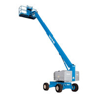
Category: Boom Lifts
|
Size: 10 MB
Table of Contents
Advertisement
Terex Z-30/20N Maintenance Manual (198 pages)
Brand: Terex
|
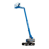
Category: Boom Lifts
|
Size: 8 MB
Table of Contents

Terex Z-30/20N Maintenance Manual (192 pages)
Brand: Terex
|
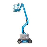
Category: Boom Lifts
|
Size: 5 MB
Table of Contents
Advertisement
Terex Z-30/20N Maintenance Manual (185 pages)
Brand: Terex
|
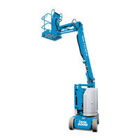
Category: Boom Lifts
|
Size: 4 MB
Table of Contents
Terex Z-30/20N Service And Repair Manual (113 pages)
Brand: Terex
|
Category: Boom Lifts
|
Size: 3 MB
Table of Contents

Terex Z-30/20N Operator's Manual (61 pages)
Brand: Terex
|
Category: Boom Lifts
|
Size: 3 MB
Table of Contents

Terex Z-30/20N Operator's Manual (59 pages)
Brand: Terex
|
Category: Boom Lifts
|
Size: 6 MB
Table of Contents
Terex Z-30/20N Operator's Manual (39 pages)
boom lift
Brand: Terex
|
Category: Lifting Systems
|
Size: 0 MB