Sign In
Upload
Manuals
Brands
Teledyne Manuals
Analytical Instruments
6000A
Teledyne 6000A Manuals
Manuals and User Guides for Teledyne 6000A. We have
1
Teledyne 6000A manual available for free PDF download: Operating Instructions Manual
Teledyne 6000A Operating Instructions Manual (94 pages)
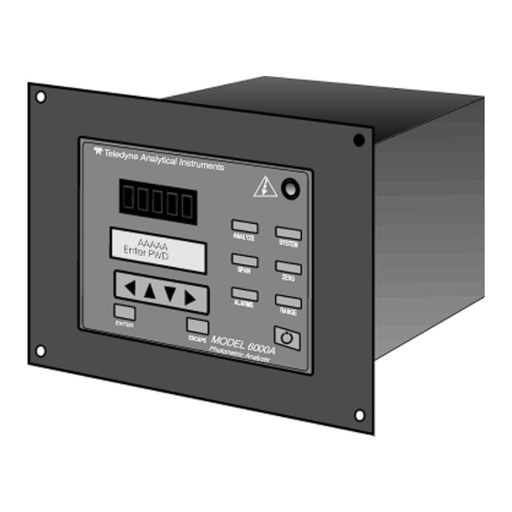
Photometric Analyzer
Brand:
Teledyne
| Category:
Analytical Instruments
| Size: 1 MB
Table of Contents
Operating Instructions 6000A Model
6
Operating Instructions
1
Table of Contents
6
1 Introduction
9
Main Features of the Analyzer
9
Overview
9
Typical Applications
9
Control Unit Inner Control Panel
10
Control Unit Interface Panel
12
2 Installation
15
Unpacking the Control Unit
15
Mounting the Control Unit
15
Electrical Connections
17
Testing the System
24
3 Operation
25
Introduction
25
Using the Data Entry and Function Buttons
25
The System Function
28
Setting up an Auto-Cal
28
Entering the Password
30
Password Protection
30
Installing or Changing the Password
31
Logging out
32
System Self-Diagnostic Test
32
Checking Linearity with Algorithm
33
The Model Screen
33
Digital Flter Setup
34
Filter or Solenoid Setup
36
Hold/Track Setup
36
Calibration/Hold Timer Setup
37
Analog 4 to 20 Ma Output Calibration
38
Model
39
The Zero and Span Functions
39
Auto Mode Zeroing
40
Zero Cal
40
Manual Mode Zeroing
41
Auto Mode Spanning
42
Cell Failure
42
Span Cal
42
Manual Mode Spanning
43
The Alarms Function
44
The Range Select Function
46
Manual (Select/Define Range) Screen
46
Auto Screen
47
Precautions
48
The Analyze Function
49
Programming
50
The Set Range Screen
50
Manual Mode Linearization
52
The Curve Algorithm Screen
52
Auto Mode Linearization
53
Appendix
53
Fuse Replacement
55
4 Maintenance
55
System Self Diagnostic Test
56
Major Internal Components
57
Cleaning
58
Model 6000A Specifications
58
Part II: Analysis Unit
59
Table of Contents
60
Operational Theory
63
Introduction
63
Method of Analysis
63
Optical Bench
64
Photometer Amlifier
67
Automatic Zero System
68
System Description
69
Photommeter
69
Source Module
70
Detector Module
71
Sample Cell
71
Sample Systems
72
Installation
77
Unpacking the Analyzer
77
Installing & Connecting the Analyzer
77
User Connections
77
Compressed Air Supply
78
Electrical Power Connections
78
Pipe Connections
78
Sample Delivery System
78
Signal and Alarm Output Connections
78
Draining the System
79
Testing the System
79
Calibration
79
Calibration Fluids
79
Maintenance
81
Routine Maintenance
81
System Visual Check and Response Procedure
81
Routine Maintenance
82
Suggested Preventive Maintenance Schedule
82
Service Procedures and Adjustments
83
Electronics
83
Power Supply Test Points
83
Oscilloscope Display of the I to E Converter Output
84
Setup of the Signal Processing Front-End Amplifier
84
Balancing the Optics for Equal Light Transmission with Zero Fluid in the Sample Cell
85
Inverting Amplifier
86
Setup of the Logarithmic Amplifier
86
Battery-Powered Oscilloscope Synchronization Point
87
Integrated Reference and Measuring Signals
87
Interface Board Terminal Strip
87
Appendix A-1 Specifications
91
Recommended 2-Year Spare Parts List
93
Drawing List
94
Advertisement
Advertisement
Related Products
Teledyne 6000B
Teledyne 6200A
Teledyne 6400A
Teledyne 6020
Teledyne 6650B
Teledyne OLCT 60d
Teledyne OLCT 60id
Teledyne 6712SR
Teledyne 68-2130-006
Teledyne 69-5243-095
Teledyne Categories
Measuring Instruments
Analytical Instruments
Test Equipment
Digital Camera
Laboratory Equipment
More Teledyne Manuals
Login
Sign In
OR
Sign in with Facebook
Sign in with Google
Upload manual
Upload from disk
Upload from URL