Sign In
Upload
Manuals
Brands
Tektronix Manuals
Stereo Receiver
AWG520
Tektronix AWG520 Manuals
Manuals and User Guides for Tektronix AWG520. We have
3
Tektronix AWG520 manuals available for free PDF download: User Manual, Service Manual, Specification Sheet
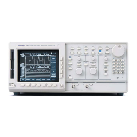
Tektronix AWG520 User Manual (464 pages)
Arbitrary Waveform Generator
Brand:
Tektronix
| Category:
Test Equipment
| Size: 5 MB
Table of Contents
Table of Contents
5
Figure 2-15: Double Windows
13
Figure 2-16: Overwrite Confirmation
13
General Safety Summary
19
Preface
21
Manual Structure
21
Conventions
22
Related Manuals
23
Contacting Tektronix
23
Product Description
25
Table 1-1: AWG 500-Series Waveform Editors
25
Accessories and Options
26
Table 1-2: Standard Accessories
26
Table 1-3: Optional Accessories
26
Table 1-4: Options
27
Incoming Inspection
29
Installation
30
Table 1-5: Fuse and Fuse Cap Part Number
31
Table 1-6: Power Cord Identification
32
Powering the Instrument
33
Figure 1-1: Rear Panel Power Switch, Fuse Holder, and Power Connector
33
Figure 1-2: Location of the ON/STBY Switch
34
Operating Basics
37
Functional Overview
38
Front Panel Controls
39
Figure 2-1: Front Panel Controls
39
Figure 2-2: Front Panel Keypad Area
40
Figure 2-3: Front Panel Trigger and Output Controls
41
Rear Panel
42
Figure 2-4: Rear Panel Map
42
Basic Operations
43
Menu Operations
43
Figure 2-5: Menu Buttons, Bezel Menu Buttons, and the CLEAR MENU Button
43
Figure 2-6: Bottom and Side Menus
44
Figure 2-7: Pop-Up Menu Example
45
Table 2-1: Side Menu Elements
45
Numeric Input
46
Figure 2-8: Dialog Box Example
46
Figure 2-9: Knob Icon Displayed in Status Display Area
47
Figure 2-10: Keypad Buttons
48
Text Input
49
Figure 2-11: Three Type of Input Text Dialog Boxes
49
Shortcut Controls
50
Figure 2-12: Shortcut Controls
50
Table 2-2: Text Input Button Functions
50
File Management
51
Table 2-3: Shortcut Controls
51
Table 2-4: AWG500-Series Waveform Generator File Types
52
Table 2-5: Drive and Directory Menus
52
Copying Files
53
Deleting Files
53
Figure 2-13: Files and Directories with Read Only Attribute
54
Figure 2-14: Input Filename Dialog Box
55
Double Windows
56
Table 2-6: Waveform Record Length Adjustment Messages
56
Window Operation
57
Table 2-7: File Operation in Double Windows
57
Table 2-8: Confirmation Selection for Copy-All and Move-All Operations
58
Quick View
59
Figure 2-17: File List Window Examples - in Which Quick View Is Available
59
Figure 2-18: Viewing a File by Quick View Function
60
Editor Overview
61
Editor Modes
61
Table 2-9: Editors
61
The Main Edit Screen
62
Figure 2-19: Edit Main Screen
62
Table 2-10: Edit Screen Bottom Menu Buttons
62
Loading a Waveform File to Edit
63
Creating a New Waveform
64
Figure 2-20: Edit Top Level Menu Screen with Edit Side Menu
64
Table 2-11: Edit Side Menu Buttons
64
Editor Screen Elements
65
Cursors and Editing
65
Figure 2-21: Editor Screen Elements
65
Multiple Editor Windows
66
Figure 2-22: Cursors and Edit Area
66
Figure 2-23: Multiple Editor Windows
67
Quitting Editors
68
Setup Overview
69
The Main Setup Screen
69
Figure 2-24: Setup Main Screen
69
Table 2-12: Setup Screen Parameter Icons
70
Table 2-13: Setup Bottom Menu Buttons
70
Loading a Waveform File to Output
71
Figure 2-25: Setup Waveform/Sequence Menu
71
Viewing a Waveform
72
Figure 2-26: Viewing a File in the Setup Screen
72
Editing a Waveform
73
Setting Waveform Output Parameters
73
Table 2-14: Setup Output Parameter Operations
74
Outputting a Waveform
76
Saving and Restoring Setup Parameters
76
Tutorials
77
Optional Equipment
77
Before Starting Tutorials
78
Figure 2-27: Cable Connection between Waveform Generator and Oscilloscope
78
Figure 2-28: Initial Screen (for the AWG520)
78
Tutorial 1: Instrument Setup
79
Figure 2-29: System Utility Screen
79
Adjust Screen Brightness
80
Tutorial 2: Loading and Outputting a Sample Waveform
81
Figure 2-30: the Select File List
81
Figure 2-31: Viewing a Waveform Loaded into Memory
82
Tutorial 3: Creating and Editing Standard Function Waveforms
84
Tutorial 4: Editing a Waveform Using Quick Editor
91
Tutorial 5: Using the Equation Editor
95
Tutorial 6: Creating and Running Waveform Sequences
98
Table 2-15: Waveforms to be Used in Sample Sequences
98
Table 2-16: Sequence Table Contents in SUBSEQ.SEQ
101
Table 2-17: Sequence Table Contents in MAINSEQ.SEQ
103
File Transfer Interface Outline
108
Menu Structures
109
SETUP Menu Hierarchy
110
EDIT Menu Hierarchy
113
APPL Menu Hierarchy
119
UTILITY Menu Hierarchy
122
Reference
125
Overview
125
Process Flow
125
Table 3-1: AWG500-Series Waveform Generator Main Menus
126
The Graphical Waveform Editor
127
Editor Screen Elements
127
Table 3-2: Waveform Editor Screen Elements
128
Table 3-3: Waveform Editor Bottom Menu
129
The File Menu
130
Table 3-4: Waveform Record Length Adjustment Messages
131
The Operation Menu
132
Table 3-5: Standard Function Waveform Dialog Box Parameters
133
Table 3-6: Shift Register Generator Dialog Box Setting Parameters
140
Table 3-7: Set Pattern Dialog Box Parameters
141
The Tools Menu
144
Table 3-8: Mathematical Function Commands
145
Table 3-9: Compare Dialog Box Parameters
148
Table 3-10: Convolution Dialog Box Parameters
149
Table 3-11: Correlation Dialog Box Parameters
149
Table 3-12: Digital Filter Dialog Box Parameters
151
The Zoom/Pan Menu
154
The Window Menu
155
The Settings Menu
155
The Pattern Editor
159
About Waveform and Pattern Files
159
Starting the Pattern Editor
160
The File Menu
161
The Operation Menu
161
The Tools Menu
161
Executing Conversion
165
The Zoom/Pan Menu
165
The Window Menu
165
The Settings Menu
165
The Undo! Command
165
Selecting Data Bits to Edit
166
Defining Edit Area
167
Creating a Pattern
168
Creating Standard Patterns
169
Importing Data from Files
170
Set Pattern
170
The Table Editor
173
Opening the Table Editor
173
Editing Table Data
174
The Equation Editor
175
Starting the Equation Editor
175
Using the Equation Editor
177
Using an External Keyboard
179
Entering Keywords and Functions
180
Compiling Equations
180
Waveform Programming Language
183
Command Syntax
183
User-Defined Variables
184
Waveform Files
185
Command Descriptions
187
Group Control
194
Math Functions
198
Command Syntax
199
Math Operators
200
Programming Examples
205
The Sequence Editor
215
Starting the Sequence Editor
215
Sequence Table Editing
217
Cursor Movement
217
Sequence Table Fields
219
The Setup Window
227
Setup Screen Elements
227
The Waveform/Sequence Menu
229
The Vertical Menu
231
The Horizontal Menu
234
The Run Mode Menu
238
The Trigger Menu
240
The Noise Menu
242
The Save/Restore Menu
243
Digital Output Level (Option 03 Only)
244
Waveform, Pattern and Sequence Waveform Output
245
The APPL Window
249
Disk Application
249
Network Application
258
Operation Flow
258
Jitter Composer Application
265
The UTILITY Window
273
External Keyboards
273
Setting General Purpose Knob Direction
274
Formatting a Floppy Disk
275
Displaying Disk Usage
275
CRT Brightness
275
Displaying Instrument Status
276
Internal Clock (Date and Time)
276
Resetting the Instrument
276
Connecting to a GPIB Network
277
Ethernet Networking
279
Connecting to the Ethernet
279
Testing the Network Connection
281
Hardcopy
286
Calibration and Diagnostics
288
Power on Diagnostics
290
Upgrading the System Software
293
Quick Editing
295
Screen Display
295
Quick Edit Mode
296
Quick Edit Mechanism
296
About Smoothing
296
Quick Controls
297
Starting Quick Edit
298
Exiting Quick Edit
298
Setting Parameters
299
Moving Cursor
299
Renewing Edit Buffer
300
About Undo
300
Capturing Waveforms
301
Possible Instruments
301
Basic Concept on Communication for Capturing
301
Procedures for Capturing Waveforms
302
About Transferred Files
303
File Conversion
305
Import
305
Export
307
Convert between Waveform and Pattern
307
Executing File Conversion
307
File Management
309
Command Summary
309
Path Name
309
File Operations
310
Selecting Files
311
File Operation in Double Windows
312
FG Mode
317
Change the Generator Mode
318
Parameters
320
Appendix A: Specifications
325
Performance Conditions
325
Electrical Specification
326
Mechanical Specification
338
Environmental Specification
339
Certification and Compliances
340
Appendix B: Performance Verification
343
Conventions
343
Self Tests
345
Performance Tests
349
Related Information
350
Equipment Required
350
Operating Mode Tests
355
Clock Frequency Tests
362
Amplitude and Offset Accuracy Tests (Normal out
364
Amplitude, Offset Accuracy and Rise Time Tests (Direct da out
368
Pulse Response Tests
372
Sine Wave Tests
375
Internal Trigger Tests
377
Trigger Input Tests
379
Event Input and Enhanced Mode Tests
384
10 Mhz Reference Input Tests
391
External Clock Input Tests
393
Add Input Tests
395
Marker Output Tests
397
Marker Delay Tests
401
Digital Data Output Tests (Option 03 Only
404
Clock Output Tests
408
Noise Output Tests
410
Appendix C: Inspection and Cleaning
413
Exterior Inspection
413
Appendix D: Repacking for Shipment
415
Appendix E: Sample Waveforms
417
Waveform File Descriptions
418
Appendix E: Sample Waveforms
419
Appendix F: Theory of Operation
429
Block Diagrams
429
External Clock Input
431
Trigger Control
432
RUN Modes
432
Waveform Edit
435
Appendix G: Sequence File Text Format
437
Line Descriptions
437
Jump Settings
438
Appendix H: Miscellaneous
441
Sampling Theorem
441
Code Conversion
447
Advertisement
Tektronix AWG520 Service Manual (273 pages)
Arbitrary Waveform Generator
Brand:
Tektronix
| Category:
Portable Generator
| Size: 6 MB
Table of Contents
Table of Contents
9
Table 1-1: AWG 500-Series Waveform Editors
26
Table 1-2: Operation Modes
29
Table 1-3: Arbitrary Waveforms
29
Table 1-4: Clock Generator
30
Table 1-5: Internal Trigger Generator
30
Table 1-6: Main Output
30
Table 1-7: Filter
32
Table 1-8: Auxiliary Outputs
33
Table 1-9: Period Jitter (CH1 MARKER1 OUT)
34
Table 1-10: Cycle to Cycle Jitter (CH1 MARKER1 OUT)
34
Table 1-11: Period Jitter (CLOCK OUT)
35
Table 1-12: Cycle to Cycle Jitter (CLOCK OUT)
35
Table 1-13: Digital Data out (Option 03)
35
Table 1-14: Auxiliary Inputs
36
Table 1-15: Funcion Generator (FG)
38
Table 1-16: Display
39
Table 1-17: Timer
39
Table 1-18: AC Line Power
39
Table 1-19: Interface Connectors
39
Figure 1-1: Dimensions
40
Table 1-20: Mechanical
40
Table 1-21: Installation Requirement
41
Table 1-22: Environmental
41
Table 1-23: Certifications and Compliances
42
Figure 1-2: Signal Timing
44
Table 2-1: Power-Cord Conductor Identification
49
Table 2-2: Power Cord Identification
49
Figure 2-1: Menu Buttons, Bezel Menu Buttons, and the CLEAR MENU
54
Figure 2-2: Bottom and Side Menus
55
Figure 2-3: Pop-Up Menu Example
56
Table 2-3: Side Menu Elements
56
Figure 2-4: Dialog Box Example
57
Button
58
Figure 2-5: Knob Icon Displayed in Status Display Area
58
Figure 2-6: Keypad Buttons
59
Figure 2-7: Three Type of Input Text Dialog Boxes
60
Table 2-4: Text Input Button Functions
61
Figure 2-8: Shortcut Controls
62
Table 2-5: Shortcut Control Descriptions
62
Table 2-6: AWG500-Series Waveform Generator File Types
63
Table 2-7: Drive and Directory Menus
64
Figure 2-9: Files and Directories with Read Only Attribute
66
Figure 2-10: Input Filename Dialog Box
66
Table 2-8: Waveform Record Length Adjustment Messages
67
Figure 4-1: Diagnostic Menu
75
Figure 4-2: Calibration Result Message Box
77
Table 4-1: Diagnostic Categories and Error Codes
78
Table 4-2: Module Test Error Code Examples
81
Table 4-3: Waveform Memory Cell Test Errors
82
Figure 4-3: EVENT in Connector Pins and Signals and Ground Closure Connector with 9-Pin D-Type Connector
85
Figure 4-4: Loading File; Selecting Storage Drive
86
Figure 4-5: Cont Mode Initial Test Hookup
94
Figure 4-6: Triggered Mode Initial Test Hookup
96
Figure 4-7: Relationship between Trigger Signal and Waveform Output
97
Figure 4-8: Relationship between Gate Signal and Waveform Output
99
Figure 4-9: Clock Frequency Initial Test Hookup
101
Figure 4-10: Amplitude Accuracy Initial Test Hookup
103
Figure 4-11: Direct da out Amplitude Accuracy Initial Test Hookup
107
Figure 4-12: Direct da out Pulse Rise Time Initial Test Hookup
109
Figure 4-13: Pulse Response Initial Test Hookup
111
Figure 4-14: Sine Wave Initial Test Hookup
114
Figure 4-15: Internal Trigger Initial Test Hookup
116
Figure 4-16: Trigger Input Initial Test Hookup
118
Figure 4-17: Trigger Signal (+5V Check1)
120
Figure 4-18: Trigger Signal (+5V Check2)
121
Figure 4-19: Trigger Signal (-5V Check1)
122
Tektronix AWG520 Specification Sheet (4 pages)
Arbitrary Waveform Generators
Brand:
Tektronix
| Category:
Portable Generator
| Size: 0 MB
Advertisement
Advertisement
Related Products
Tektronix AWG5204
Tektronix AWG5202
Tektronix AWG5208
Tektronix AWG5200 Series
Tektronix AWG5014C
Tektronix AWG5002C
Tektronix AWG50BUP Option S39
Tektronix AWG5004
Tektronix AWG5000B Series
Tektronix AWG510
Tektronix Categories
Test Equipment
Measuring Instruments
Amplifier
Portable Generator
Printer
More Tektronix Manuals
Login
Sign In
OR
Sign in with Facebook
Sign in with Google
Upload manual
Upload from disk
Upload from URL