Advertisement
Quick Links
A r b i t r a r y Wa v e f o r m G e n e r a t o r s
AWG520
AWG520.
AWG520 Solves Communications Physical Layer
and Media Storage Design and Test Challenges
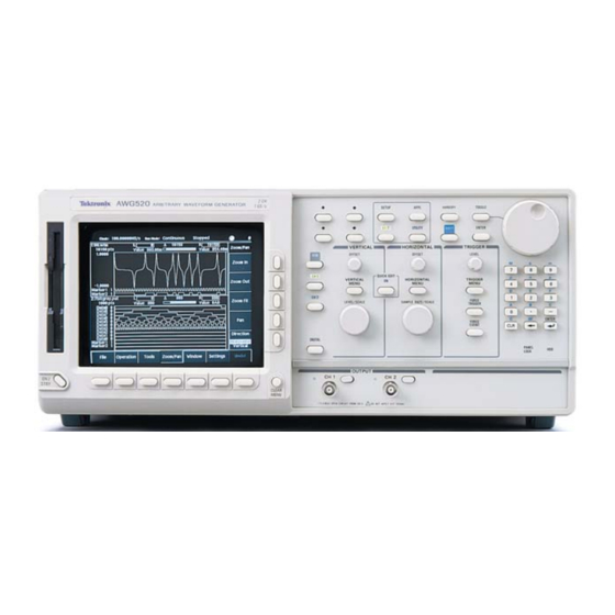
The AWG520's unique design combines a
graphical editing display with powerful out-
put capabilities to simplify the creation of
arbitrary and complex waveforms and
enable easy on-screen waveform editing.
With the AWG520's many built-in intuitive
and powerful features, you can easily develop
and edit custom waveforms. Option 03 adds
an independent 10-bit-wide digital data
port that can be used in conjunction with
marker outputs for data generation up to
14-bits wide at up to 1 GHz (14-bits,
AWG520). Direct waveform transfer
capability makes the AWG520 the perfect
complement to selected Tektronix
oscilloscopes.
www.tektronix.com/signal_sources
1
Arbitrary Waveform Generators
•
The AWG520 can easily generate telecom
signals which complement masks from a
digital oscilloscope.
Features & Benefits
Two Channels with 10-Bit
Vertical Resolution
Independent 10-Channel,
1 GHz Digital Data Generation
(Opt. 03)
Built-in Independent Real-time
Noise Generation
External Clock Input
Permits Jitter Insertion
and Synchronization
Supports Direct External Clock
and 10 MHz Reference Input
Unique Real-time Sequencing
Links Multiple Waveform Files
Creating Waveforms of Nearly
Infinite Length
Built-in Application Generates
Jitter, Data Communication
and Disk Drive Waveforms
User Modified Isolation
Pulse for Disk Drive Testing
Built-in 10 GB Hard Drive
for Mass Data Storage that
Can Optionally Be Made
Removable for Secure
Applications (using Opt. 11)
Optional 128 MB Flash Disk
for ATE Applications (Opt. 10)
Replace Standard Function
and Sweep Generators in
Wide Range of Applications
Applications
Communications Design
and Test:
– Low Frequency Modulated
RF with Components Using
AM and FM Modulation
– Digital Information Encoding
Using FSK, PSK and QAM
(Quadrature Modulation)
for Cellular, Fax and Modem
Communications
Optical Communications
Design and Test:
– Reflections, Crosstalk and
Ground Bounce Simulation
Pulse Generation:
– Duty Cycle Ranges from
0% to 100% for NRZ Data
– Testing Clock/Gating
Width Variations
Real-world Simulations:
– Corrupt Ideal Waveforms
– Add Jitter to Waveforms
– EMP/EMI and Other
System Noise
– Power Supply Noise
and Ripple
– Transducer Simulation
Advertisement

Summary of Contents for Tektronix AWG520
- Page 1 AWG520 AWG520. AWG520 Solves Communications Physical Layer and Media Storage Design and Test Challenges The AWG520’s unique design combines a graphical editing display with powerful out- put capabilities to simplify the creation of arbitrary and complex waveforms and enable easy on-screen waveform editing.
- Page 2 Arbitrary Waveform Generators AWG520 Characteristics Operating Modes Continuous – Waveform is iteratively output. If a sequence is defined, the sequence order and repeat functions are applied. Triggered – Waveform is output only once when an external, internal GPIB/Ethernet or manual trig- ger is received.
- Page 3 Auxiliary Outputs Marker – Number: AWG520: 4. Level: Hi/Lo: –2.0 V to 2.0 V (0.05 V to 4 V into 50 Ω; –4.0 V to 4.0 V (0.1 V to 8 V into 1 MΩ. Resolution: 0.05 V. Accuracy: Within ±0.1 V ±5% of setting.
-
Page 4: Ordering Information
Product(s) complies with IEEE Standard 488.1-1987, RS-232-C, and with Tektronix Standard Codes and Formats. Copyright © 2004, Tektronix, Inc. All rights reserved. Tektronix products are covered by U.S. and foreign patents, issued and pending. Information in this publication supersedes that in all previously published material. Specification and price change privileges reserved.


Need help?
Do you have a question about the AWG520 and is the answer not in the manual?
Questions and answers