Sign In
Upload
Manuals
Brands
Tektronix Manuals
Measuring Instruments
2715
Tektronix 2715 Manuals
Manuals and User Guides for Tektronix 2715. We have
4
Tektronix 2715 manuals available for free PDF download: Service Manual, User Manual, Programmer's Manual, Reference
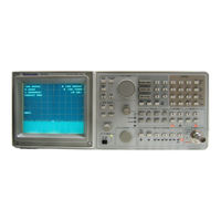
Tektronix 2715 Service Manual (682 pages)
Spectrum Analyzer
Brand:
Tektronix
| Category:
Measuring Instruments
| Size: 9.93 MB
Table of Contents
List of Figures
7
Table of Contents
7
List of Tables
11
Table 1-1: CATV Characteristics
20
Figure 1-1: Typical Accuracy Limits for Carrier-To-Noise Measurement
25
Figure 1-2: Typical Accuracy Limits for CTB Measurement
25
Figure 1-3: Typical Accuracy Limits for Nongated CSO Measurement
26
Figure 1-4: Typical Accuracy Limits for Gated CSO Measurement
26
Figure 1-5: Typical ACL Measurement Limits for 2 Db Accuracy
27
Figure 1-6: Typical D/U Measurement Range Limits for 2 Db Accuracy
27
Figure 1-7: Typical Digital Signal CSO Measurement Range Limit for 2 Db Accuracy
28
Figure 1-8: Typical Digital Signal CTB Measurement Range Limit for 2 Db Accuracy
28
Table 1-2: Frequency-Related Characteristics
29
Table 1-3: Frequency/Amplitude Related Characteristics
31
Table 1-4: Amplitude-Related Characteristics
32
Table 1-5: Input/Output Signal Characteristics
35
Table 1-6: Power Requirements
37
Table 1-7: Supplementary Characteristics Due to Options
37
Table 1-8: General Characteristics
38
Table 1-9: Environmental Characteristics
39
Table 1-10: Physical Characteristics
40
Table 1-11: Certifications and Compliances
41
Table 1-12: Safety Certification Compliance
42
Table 1-13: Safety Standards
42
Figure 2-1: 2715 Front Panel Keys
47
Figure 3-1: Main Block Diagram
60
Figure 3-2: Display System Diagram
66
Figure 3-3: Attenuator and 1St Converter Diagram
68
Figure 3-4: Equivalent Circuit for the Bandpass (4 Cavity) Filter
69
Figure 3-5: Block Diagram of RF Mother Board
70
Figure 3-6: 1St lo Interface and 1St lo Diagram
72
Figure 3-7: 1St lo Buffer Amplifier Diagram
73
Figure 3-8: Reference Oscillator Diagram
75
Figure 3-9: Crystal Heater and 15 V Regulation Circuit
76
Figure 3-10: Oscillator AC Equivalent
77
Figure 3-11: Oscillator DC Equivalent
78
Table 3-1: Input and Output Bit Definition
79
Figure 3-12: Phase Lock Center Frequency Control Configuration for Wide Spans (Unlocked, Sweep Main Coil)
86
Figure 3-13: Phase Lock Center Frequency Control Configuration for Moderate Spans (Unlocked, Sweep FM Coil)
87
Figure 3-14: Phase Lock Center Frequency Control Configuration for Narrow Spans (Locked, Sweep VCO)
88
Figure 3-15: Variable Resolution Module Diagram
92
Figure 3-16: RF Options Diagram
94
Table 3- 2: Mode Control Register 1
99
Table 3- 3: Mode Control Register 2
100
Table 3- 6: Mode Control Register 2
101
Table 3-4: Truth Table for the B,C-Save a Display Screen Offset
101
Table 3-5: Truth Table for the Acquisition Modes
101
Table 3-7: Enhanced Mode MKRWFM[3
102
Table 3-9: Display Control Register
103
Table 3-10: Scroll Register
104
Table 3-11: Memory Map for the Display Storage Board
106
Table 3-12: Control Register Latch and Tristate Buffer Reference Designators and Microprocessor I/O Port Address Location
107
Table 3-13: Input Conditions Required to Write Either the Max or Min Accumulators to Waveform Memory
111
Table 3-14: Page Number/Waveform Relation
113
Table 3-15: Interrupt Controller Input Connections
121
Table 3-16: Configuration of Jumpers/Wires for Various Memory IC Sizes
123
Table 3-17: Definition of Software Jumpers
124
Sensitivity
165
REFERENCE LEVEL - -50 Dbm
166
Set the VIDEO FILTER to 10 Hz by Pressing UTIL 2 5
166
SPAN/DIV 5 Mhz
166
VERTICAL SCALE 10 Db
166
200 Khz
171
300 Khz - - 50 Dbm
171
Connect a 110 Mhz, - -85 Dbm Signal to the RF INPUT
171
10 Khz
172
10 Khz
179
Khz 300 Hz - - 70 Dbm
179
Advertisement
Tektronix 2715 User Manual (360 pages)
Spectrum Analyzer
Brand:
Tektronix
| Category:
Measuring Instruments
| Size: 1.45 MB
Table of Contents
Table of Contents
6
Figure 2-1: Display with Factory Default Power-Up Settings
32
Figure 2-2: Normal On-Screen Data Readouts
33
Figure 2-3: Typical Measurement Result Display
39
Figure 2-4: the Primary Controls
40
Figure 2-5: Calibrator Signal and Harmonics
41
Figure 2-6: Calibrator Signal Fundamental
45
Figure 3-1: Layout of the Text Screen in the Spectral Display Mode
49
Figure 3-2: Layout of the Text Screen in the Menu Display Mode
50
Figure 3-3: the Frequency/Marker Function Block
51
Figure 3-4: Fundamental Analyzer Controls
52
Figure 3-5: the Keypad
54
Figure 3-6: Display Register Control
54
Figure 3-7: Vertical Scale and Other Controls
55
Figure 3-8: Resolution BW and Sweep Control
56
Figure 3-9: the 2715 Back Panel
58
Dedicated Controls
71
Fundamental Operations
73
Span/DIV
74
Frequency Entry
77
(Normal Mode)
77
Frequency Entry (Noncatv Mode)
79
Ref Level
81
Enhanced Versatility
83
Res BW
83
Video Filter
86
Vert Scale
88
Sweep
89
Level
92
Display Storage
92
Figure 4-1: Example of a Waterfall Display
97
Freq/Mkrs
98
Miscellaneous Controls
105
Figure 4-2: Typical Plotter Output Showing TV Channel Spectrum
106
CATV Measurements
109
CATV Preliminary Information
111
Table 5-1: Safe Maximum Signal Levels
112
General (CATV) 2715 Mode
114
Figure 5-1: CATV MEASUREMENTS Menu
114
Table 5-2: Signal Type Measurements
115
Figure 5-2: Channel 2 of the STD Channel Table Selected for Edit with Menu Set to Change SCRAMBLED (Toggles between YES/NO)
117
Table 5-3: Menu Selections
118
Figure 5-3: Channel with FINISH Selected
119
Table 5-4: STD
120
Table 5-5: HRC
122
Table 5-6: IRC
125
CARRIER LEVEL and AVERAGED POWER Measurement
130
Figure 5-4: Carrier Level, Averaged Power Measurement Results
134
CARRIER SURVEY Measurement
135
Figure 5-5: Typical Carrier Survey Report Screen
137
MODULATION DEPTH Measurement
138
Table 5-7: Examples of Cycle Delay/Target Line Duration Interaction
141
AURAL (FM) DEVIATION Measurement
142
CARRIER-TO-NOISE, DESIRED-To-UNDESIRED Measurement
145
Table 5-8: Locations of Noise Measurement
147
HUM/LFD Measurement
150
Frequency Response
153
Figure 5-6: Typical Frequency Response Display Without Reference
155
Figure 5-7: Typical Frequency Response Display with Reference
156
ADJACENT CHANNEL LEAKAGE Measurements
157
CTB and CSO Measurements
159
Figure 5-8: Typical CTB (or CSO) Measurement Results Display
164
Figure 5-9: Typical Continuous Mode Results Display
169
CROSS MODULATION Measurement
170
In-Channel Response Measurement
172
Auxiliary Operations
178
Spectrum Analyzer Menus
181
Using the Menus
183
Figure 6-1: the INPUT Menu
184
Figure 6-2: Sweep/Trigger Menu with SWEEP RATE Selection Chosen
184
Input
186
Table 6-1: Equivalent Decibel - Voltage Values
194
Mkr/Freq
199
Table 6-2: AUTO Tuning Increment
204
Dspl
209
Ensemble Averaging
210
Appl
225
Demod
238
Util
242
The Audio Alert
253
Table 6-3: the File System
258
Table 6-4: Additional File System
258
Swp/Trig
265
User Def
271
Table A-1: CATV Characteristics
278
Table A-2: Frequency-Related Characteristics
287
Table A-3: Frequency/Amplitude Related Characteristics
289
Table A-4: Amplitude-Related Characteristics
290
Table A-5: Input/Output Signal Characteristics
293
Table A-6: Power Requirements
295
Table A-7: Supplementary Characteristics Due to Options
295
Table A-8: General Characteristics
296
Table A-9: Environmental Characteristics
297
Table A-10: Physical Characteristics
298
Table A-11: Certifications and Compliances
299
Table A-12: Safety Certification Compliance
300
Table A-13: Safety Standards
300
Table E-1: 9-Pin Female to 9-Pin Female Null-Modem Cable
331
Table E-2: 9-Pin Female to 25-Pin Female Null-Modem Cable
332
Table E-3: 9-Pin Female to 25-Pin Male Extension Cable
333
Table F-1: Standard Accessories
335
Table F-2: Optional Accessories
335
Table F-3: Power Cord Identification
336
Tektronix 2715 Programmer's Manual (308 pages)
Spectrum Analyzer
Brand:
Tektronix
| Category:
Measuring Instruments
| Size: 1.12 MB
Table of Contents
Table of Contents
7
Figure 6-2: Terminal Display before CATV XMOD Test Begins
8
Figure 6-3: Terminal Display of CATV XMOD Test Results
8
Figure 6-4: a Remote Menu
8
Figure 6-5: Prompting for a Numeric Entry
8
Figure 6-6: Specifying a Numeric Value
8
Figure 6-7: a Remote Submenu
8
Figure 6-9: Possible Data Print/Plot Scheme
8
Figure A-1: RS-232 Representation of a Character
8
Figure A-2: Rear Panel RS-232 Connector
8
Figure B-1: IEEE Std 488.1 (GPIB) Connector
8
Figure 1-1: Two RS-232 System Configurations
16
Menu
17
Figure 1-2: the RS-232 Port Configuration Menu
18
Figure 1-3: Typical Small Instrument System for GPIB
26
Figure 1-4: Connecting Multiple Instruments on the GPIB
28
Figure 1-5: the Spectrum Analyzer's GPIB Port Configuration
29
Configuration Menu
29
Table 1-1: National Instruments PCII Board Characteristics
31
Table 1-2: National Instruments PCIIA Board Characteristics
31
Table 1-3: TEK_SA Device Characteristics
32
Commands
49
Table 3-1: Commands and Queries
58
Table 3-2: FREQ/MKRS Front Panel Commands
61
Table 3-3: MKR/FREQ Menu Commands
62
Table 3-4: FREQUENCY, SPAN/DIV and REF LEVEL Front Panel
64
Table 3-5: VERT SCALE, PLOT, and READOUT Front Panel
65
Table 3-6: INPUT Menu Commands
66
Table 3-7: SWP/TRIG Menu Commands
67
Table 3-8: SWEEP and RES BW Front Panel Commands
68
Table 3-9: DISPLAY STORAGE Front Panel Commands
69
Table 3-10: DSPL Menu Commands
70
Table 3-11: CATV/APPL Menu Commands (CATV Mode Active)
74
Table 3-13: UTIL Menu Commands
80
Table 3-14: DEMOD Menu Commands
82
Commands
83
Table 3-15: Curve and Waveform Commands
83
Table 3-16: System-Related Commands
83
Table 3-17: Miscellaneous Commands
84
Table 4-1: Catv Command Arguments
96
Table 4-2: Catv? Query Arguments
101
Figure 4-1: Format of Curve Data
111
Figure 4-2: Spectrum Analyzer Graticule Coordinates
112
Table 4-3: File Types
121
Table 4-4: Valid File Names
122
Table 4-5: Miscellaneous Files
122
Table 4-6: Arguments of the KEY Command
130
Table 4-7: Arguments of the Wfmpre? Query
177
Table 4-8: Related Formulas
177
Table 5-1: Event Codes
183
Table 5-2: General System Status Bytes
192
Table 5-3: General Device-Dependent Status Bytes
192
Table 5-4: Specific System Status Bytes
192
Table 5-5: Specific Device-Dependent Status Bytes
193
Figure 6-1: Terminal Display of ID? Query Response
201
Figure 6-8: Possible Data Acquisition Scheme
252
Figure A-3: 9-Pin Female to 9-Pin Female Null-Modem Cable
272
Figure A-4: 9-Pin Female to 25-Pin Female Null-Modem Cable
273
Figure A-5: 9-Pin Female to 25-Pin Male Extension Cable
274
Figure B-4: Handshake Timing Sequence, Idealized
288
Advertisement
Tektronix 2715 Reference (40 pages)
Spectrum Analyzer
Brand:
Tektronix
| Category:
Measuring Instruments
| Size: 0.35 MB
Table of Contents
Table of Contents
5
Controls and Menus Reference
6
Frequency/Markers Controls
8
Fundamental Controls
10
Numeric Keypad
12
Display Controls
14
Vertical Scale
14
Display Storage Controls
16
Resolution BW and Sweep Controls
18
TRIGGER Menu
20
SWEEP Menu
20
UTIL Menu
21
MKR/FREQ Menu
21
MKR/FREQ Menu
22
CATV Menu (2714 Only)
23
CATV Menu
23
CATV Menu (2715 Only)
33
APPL Menu
37
DEMOD Menu
37
DSPL Menu
38
USER DEF Menu
39
INPUT Menu
39
Control Ranges
40
Advertisement
Related Products
Tektronix 2756P
Tektronix 2714
Tektronix 2782
Tektronix Keithley SourceMeter 2461
Tektronix KEITHLEY 2450-EC
Tektronix KEITHLEY 2604B
Tektronix KEITHLEY 2634B
Tektronix KEITHLEY 2380-120
Tektronix KEITHLEY 2380J-500-15
Tektronix KEITHLEY 2380J-120-60
Tektronix Categories
Test Equipment
Measuring Instruments
Amplifier
Printer
Portable Generator
More Tektronix Manuals
Login
Sign In
OR
Sign in with Facebook
Sign in with Google
Upload manual
Upload from disk
Upload from URL