Sign In
Upload
Manuals
Brands
Tektronix Manuals
Measuring Instruments
1502C
Tektronix 1502C Manuals
Manuals and User Guides for Tektronix 1502C. We have
2
Tektronix 1502C manuals available for free PDF download: Service Manual, User Manual
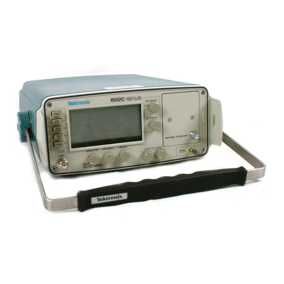
Tektronix 1502C Service Manual (254 pages)
Metallic Time-Domain Reflectometer
Brand:
Tektronix
| Category:
Measuring Instruments
| Size: 12 MB
Table of Contents
Table of Contents
6
List of Figures
8
List of Tables
13
General Safety Summary
14
Service Safety Summary
16
General Information
18
Installation and Repacking
19
Operating Instructions
22
Overview
22
Figure 1-1: Rear Panel Voltage Selector, Fuse, AC Receptacle
22
Figure 1-2: Display Showing Low Battery Indication
25
Preparing to Use the 1502C
26
Figure 1-3: 1502C Front-Panel Controls
26
Display
27
Front-Panel Controls
27
Figure 1-4: Display and Indicators
27
Menu Selections
28
Test Preparations
32
Figure 1-5: Vp Set at .30, Cursor Beyond Reflected Pulse
33
Figure 1-6: Vp Set at .99, Cursor Less than Reflected Pulse
33
Figure 1-7: Vp Set at .66, Cursor at Reflected Pulse (Set Correctly)
33
Cable Test Procedure
34
Figure 1-8: 20-Ft Cable at 5 Ft/DIV
34
Figure 1-9: Short in the Cable
34
Figure 1-10: Open in the Cable
35
Figure 1-11: 455-Ft Cable
35
Figure 1-12: 455-Ft Cable
36
Figure 1-13: Reflection Adjusted to One Division in Height
36
Figure 1-14: Return Loss
38
Figure 1-15: Ohms-At-Cursor
38
Figure 1-16: Display with VIEW INPUT Turned off
39
Figure 1-17: Display of a Stored Waveform
40
Figure 1-18: Display of a Stored Waveform
40
Figure 1-19: Waveform Moved to Top Half of Display
41
Figure 1-20: Current Waveform Centered, Stored Waveform above
41
Figure 1-21: Current Waveform Center, Stored Waveform above
42
Figure 1-22: Waveform of Three-Foot Lead-In Cable
43
Figure 1-23: Cursor Moved to End of Three-Foot Lead-In Cable
43
Figure 1-24: Cursor Moved to End of Three-Foot Lead-In Cable
44
Figure 1-25: Cursor Moved to 0.00 Ft
44
Figure 1-26: Incident Pulse at Three Divisions
45
Figure 1-27: Waveform of Short 75
45
Figure 1-28: Waveform Centered and Adjusted Vertically
46
Figure 1-29: Cursor Moved to Desired Position
46
Additional Features (Menu Selected)
47
Figure 1-30: Waveform Viewed in Normal Operation
47
Figure 1-31: Waveform Showing Intermittent Changes
47
Figure 1-32: Waveform Display with no Outgoing Pulses
48
Figure 1-33: a Captured Single Sweep
49
Operator Performance Checks
50
Specifications
60
Electrical Characteristics
60
Environmental Characteristics
62
Physical Characteristics
63
Options and Accessories
64
Option 04: YT-1 Chart Recorder
64
Option 05: Metric Default
64
Option 07: YT-1S Chart Recorder
64
Power Cord Options
64
Accessories
65
Circuit Descriptions
68
Introduction
68
Power Supply
71
Processor System
74
Option Port Interface
77
Video Processor
80
Timebase
82
Driver/Sampler
90
Front Panel
92
Display Module
95
Calibration
108
Introduction
108
Calibration Performance Check
108
Display Module Check
109
Front Panel Check
111
Horizontal Scale (Timebase) Check
114
Zero Offset Check
117
Noise Check
120
Sampling Efficiency Check
122
Offset/Gain Check
123
RAM/ROM Check
124
Aberrations Check
124
Risetime Check
126
Jitter Check
128
Option 04/07: YT-1/YT-1S Chart Recorder Check
130
Option 05: Metric Default Check
130
Adjustment Procedures
131
Visual Inspection
132
Power Supply Checks and Adjustments
132
Main Board
136
12 VDC Check and Adjust
136
Impedance Check
141
LCD Check and Adjustment
142
Zero Offset Adjust
145
After Adjustments Are Completed
147
Maintenance
148
Introduction
148
Preventive Maintenance
148
Part Removal and Replacement
149
Troubleshooting
159
Control Panel Installation
164
Installing the Case Cover over the Chassis
166
Replaceable Electrical Parts
168
Parts Ordering Information
168
Diagrams
198
General Information
198
Replaceable Mechanical Parts
228
Parts Ordering Information
228
Using the Replaceable Mechanical Parts List
228
Cable
228
Advertisement
Tektronix 1502C User Manual (127 pages)
Metallic Time-Domain Reflectometer
Brand:
Tektronix
| Category:
Measuring Instruments
| Size: 4 MB
Table of Contents
Table of Contents
6
General Information
12
Installation and Repacking
13
Table I: Shipping Carton Test Strength
14
Safety Summary
16
Operating Instructions
20
Overview
20
Figure 1-1: Rear Panel Voltage Selector, Fuse, AC Receptacle
21
Table 1-1: Fuse and Voltage Ratings
21
Figure 1-2: Display Showing Low Battery Indication
22
Preparing to Use the 1502C
24
Figure 1-3: 1502C Front-Panel Controls
24
Display
25
Figure 1-4: Display and Indicators
25
Front-Panel Controls
26
Menu Selections
27
Test Preparations
31
Table 1-2: Vp of Various Dielectric Types
31
Figure 1-5: Vp Set at .30, Cursor Beyond Reflected Pulse
32
Figure 1-6: Vp Set at .99, Cursor Less than Reflected Pulse
32
Figure 1-7: Vp Set at .66, Cursor at Reflected Pulse
32
Cable Test Procedure
33
Figure 1-8: 20-Ft Cable at 5 Ft/DIV
33
Figure 1-9: Short in the Cable
34
Figure 1-10: Open in the Cable
34
Figure 1-11: 455-Ft Cable
35
Figure 1-12: 455-Ft Cable
35
Figure 1-13: Reflection Adjusted to One Division in Height
36
Figure 1-14: Return Loss
37
Figure 1-15: Ohms-At-Cursor
38
Figure 1-16: Display with VIEW INPUT Turned off
39
Figure 1-17: Display of a Stored Waveform
39
Figure 1-18: Display of a Stored Waveform
40
Figure 1-19: Waveform Moved to Top Half of Display
41
Figure 1-20: Current Waveform Centered, Stored Waveform
41
Figure 1-21: Current Waveform Center, Stored Waveform Above, Difference below
42
Figure 1-22: Waveform of Three-Foot Lead-In Cable
43
Figure 1-23: Cursor Moved to End of Three-Foot Lead-In Cable
43
Figure 1-24: Cursor Moved to End of Three-Foot Lead-In Cable
44
Figure 1-25: Cursor Moved to 0.00 Ft
44
Figure 1-26: Incident Pulse at Three Divisions
45
Figure 1-27: Waveform of Short 75 Ohm Cable
46
Figure 1-28: Waveform Centered and Adjusted Vertically
46
Figure 1-29: Cursor Moved to Desired Position
47
Additional Features (Menu Selected)
48
Figure 1-30: Waveform Viewed in Normal Operation
48
Figure 1-31: Waveform Showing Intermittent Changes
49
Operator Tutorial
52
What Is the Tektronix 1502C
52
How Does It Do It
52
You, the Operator
52
Menus and Help
52
Getting Started
53
The Waveform up Close
56
A Longer Cable
58
Ohms-At-Cursor
59
Noise
62
Set Ref (Delta Mode)
64
View Input
68
STORE and VIEW STORE
69
View Diff
71
Menu-Accessed Functions
72
TDR Questions and Answers
77
Options and Accessories
80
Option 04: YT-1 Chart Recorder
80
Option 05: Metric Default
80
Option 07: YT-1S Chart Recorder
80
Power Cord Options
80
Test Data Record Option
81
Option de
81
Accessories
81
Appendix A: Specifications
84
Electrical Characteristics
84
Table A-1: Electrical Characteristics
84
Environmental Characteristics
86
Table A-2: Environmental Characteristics
86
Certifications and Compliances
87
Physical Characteristics
88
Table A-3: Physical Characteristics
88
Appendix B: Operator Performance Checks
90
Appendix C: Operator Troubleshooting
102
Error Messages
104
Appendix D: Application Note
108
Pulse Echo Testing of Electrical Transmission Lines
108
Using the Tektronix Time-Domain Reflectometry Slide Rule
108
Terms and Symbols
108
Relationships
109
VSWR Vs. Percent Reflected Voltage
109
Return Loss (Db) Vs. Percent Reflected Voltage
110
Percent Reflected Voltage Vs. Characteristic Line Impedance
111
Percent Reflected Voltage Vs. Load Resistance
113
Characteristic Line Impedance or Load Resistance Vs. Reflection Amplitude
113
Centimeters Vs. Inches or Meters Vs. Feet
114
Dielectric Constant Vs. Velocity Factor
115
Time Vs. Short Distances, in Centimeters or Inches (any Dielectric
115
Time Vs. Long Distances, in Meters or Feet (any Dielectric
116
Glossary
118
Advertisement
Related Products
Tektronix 1503
Tektronix 1502
Tektronix 1502B
Tektronix 1503B
Tektronix 1501
Tektronix 1L10
Tektronix 1200C01
Tektronix 1L60
Tektronix 1L5
Tektronix 131
Tektronix Categories
Test Equipment
Measuring Instruments
Amplifier
Portable Generator
Printer
More Tektronix Manuals
Login
Sign In
OR
Sign in with Facebook
Sign in with Google
Upload manual
Upload from disk
Upload from URL