Sign In
Upload
Manuals
Brands
Tekon Manuals
Microphone system
PLUS TWP-4AI4DI1UT
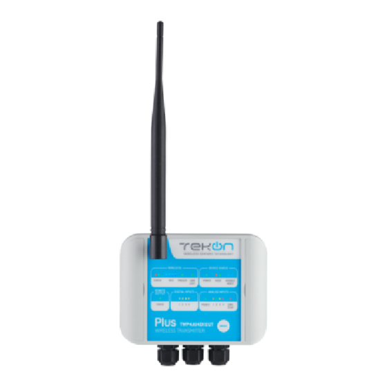
Tekon PLUS TWP-4AI4DI1UT Manuals
Manuals and User Guides for Tekon PLUS TWP-4AI4DI1UT. We have
3
Tekon PLUS TWP-4AI4DI1UT manuals available for free PDF download: Product Manual, Installation Manual
Tekon PLUS TWP-4AI4DI1UT Product Manual (59 pages)
Brand:
Tekon
| Category:
Microphone system
| Size: 5 MB
Table of Contents
Table of Contents
2
Technical Support and Assistance
6
Warnings and Safety
7
Distribution
8
Before Beginning the Installation
8
Chapter 1 - Plus Wireless System Overview
9
Introduction
9
References
9
Chapter 2 - Products
10
Plus Transmitter Twp4Ai
10
Mechanical Interface and Dimensions
10
Figure 1 - TWP4AI Transmitter Mechanical Interface and Dimensions
10
Block Diagram
11
Labels
11
Leds and Buttons Workflow
11
Figure 2 - Block Diagram of TWP4AI Transmitter
11
Figure 3 - Labels of TWP4AI Transmitter
11
Wiring
12
Table 1 - TWP4AI LED Behaviours
12
Table 2 - TWP4AI Buttons Behaviours
12
Figure 4 - TWP4AI PCB and Connectors
13
Analog Inputs
14
Figure 5 - Analog Inputs Tab in Tekon Configurator Software
14
Table 3 - TWP4AI Connectors and Functionality
14
Digital Input
15
Figure 6 - Analog Inputs Options in Tekon Configurator Software
15
Figure 7 - Digital Input Tab in Tekon Configurator Software
16
Figure 8 - Digital Input Options in Tekon Configurator Software
16
Table 4 - Description of the Possible Configurations for Digital Input Trigger
16
Configuration
17
Digital Outputs
17
Figure 9 - Digital Outputs Tab in Tekon Configurator Software
17
Table 5 - Description of the Digital Output States Related to the Link Lost Output
17
Table 6 - Description of Remote Control Output Features
18
Table 7 - Description of External Power Output
18
Plus Head Transmitter Twph-1Ut
19
Mechanical Interface and Dimensions
19
Block Diagram
19
Figure 10 - TWPH-1UT Transmitter Mechanical Interface and Dimensions
19
Figure 11 - Block Diagram of TWPH-1UT Transmitter
19
Labels
20
Leds and Buttons Workflow
20
Figure 12 - Labels of TWPH-1UT Transmitter
20
Table 8 - TWPH-1UT LED Behaviours
20
Table 9 - TWPH-1UT Button Behaviours
20
Device
21
Sensor Input
21
Figure 13 - Device Tab in Tekon Configurator Software
21
Table 10 - Description of Tekon Configurator "Device" Tab of TWPH-1UT
21
Wiring
22
Figure 14 - Sensor Input Tab in Tekon Configurator Software
22
Figure 15 - TWPH-1UT Wire Connections
22
Plus Transmitter Twp-4Ai4Di1Ut
23
Mechanical Interface and Dimensions
23
Figure 16 - TWP-4AI4DI1UT Transmitter Mechanical Interface and Dimensions
23
Block Diagram
24
Labels
24
Leds and Buttons Workflow
24
Figure 17 - Block Diagram of TWP-4AI4DI1UT
24
Figure 18 - Labels of TWP-4AI4DI1UT Transmitter
24
Wiring
25
Table 11 - TWP-4AI4DI1UT Leds Behaviours
25
Table 12 - TWP-4AI4DI1UT Buttons Behaviours
25
Figure 19 - TWP-4AI4DI1UT PCB and Connectors
26
Figure 20 - PT100 Connection
26
Figure 21 - Thermocouple Connection
26
Device
27
Figure 22 - Device Tab in Tekon Configurator Software
27
Table 13 - Description of TWP-4AI4DI1UT Connections
27
Sensor Input
28
Analog Inputs
28
Figure 23 - Sensor Input Tab in Tekon Configurator Software
28
Table 14 - Description of Tekon Configurator "Device" Tab for TWP-4AI4DI1UT
28
Figure 24 - Analog Inputs Tab in Tekon Configurator Software
29
Figure 25 - Analog Inputs Options in Tekon Configurator Software
29
Digital Inputs
30
Figure 26 - Digital Inputs Tab in Tekon Configurator Software
30
Figure 27 - Digital Input Options in Tekon Configurator Software
31
Table 15 - Description of the Possible Configurations for Digital Input Trigger
31
Digital Inputs Behaviours
32
Figure 28 - Digital Inputs Configuration and Options
32
Figure 29 - Behaviour of Digital Input Activation by Falling Edge
32
Digital Outputs
33
Figure 30 - Behaviour of Digital Input Activation by Raising Edge
33
Figure 31 - Behaviour of Digital Input Activation by both
33
Figure 32 - Digital Outputs Tab in Tekon Configurator Software
33
Table 16 - Description of the Digital Output States Related to the Link Lost Output
34
Table 17 - Description of Remote Control Output Features
34
Table 18 - Description of External Power Control Output Value
34
Figure 33 - Digital Outputs Tab in Tekon Configurator Software
35
Plus Repeater Wrp001
36
Mechanical Interface and Dimensions
36
Figure 34 - WRP001 Repeater Mechanical Interface and Dimensions
36
Block Diagram
37
Labels
37
Leds and Buttons Workflow
37
Figure 35 - Block Diagram of WRP001 Repeater
37
Figure 36 - Labels of WRP001 Repeater
37
Figure 37 - Configuration of WRP001 Repeater at Tekon Configurator Software
38
Table 19 - WRP001 LED Behaviours
38
Table 20 - WRP001 Buttons Behaviours
38
Wiring
39
Figure 38 - PLUS Repeater WRP001 Wiring
39
Plus Gateway Wgw420
40
Mechanical Interface and Dimensions
40
Figure 39 - WGW420 Gateway Mechanical Interface and Dimensions
40
Block Diagram
41
Labels
41
Leds Workflow
41
Figure 40 - Block Diagram of WGW420 Gateway
41
Figure 41 - Labels of WGW420 Gateway
41
Table 21 - WGW420 LED Behaviours
41
Wiring
42
Modbus
42
Figure 42 - Connections in PLUS WGW420 Gateway
42
Remote Devices
43
Tab Layout
43
Figure 43 - Tekon Configurator Layout of Remote Devices Tab
43
Figure 44 - TWP4AI Layout of Remote Devices Tab
43
Figure 45 - TWPH-1UT Layout of Remote Devices Tab
43
Table 22 - Modbus Addresses
43
Common Data
44
Twp4Ai
44
Twph-1Ut
44
Twp-4Ai4Di1Ut
44
Table 23 - Description of each Label from Tekon Configurator Window
44
Table 24 - Description of each Label from Tekon Configurator Window (TWP4AI)
44
Table 25 - Description of each Label from Tekon Configurator Window (TWPH-1UT)
44
Analog Outputs
45
Figure 46 - Tekon Configurator Layout of Analog Outputs Tab
45
Table 26 - Description of each Label from Tekon Configurator Window (TWP-4AI4DI1UT)
45
Table 27 - Description of each Label from Tekon Configurator Window (Analog Outputs)
45
Chapter 3 - System Configuration
47
Operation Mode
47
Site Survey Feature
47
Figure 47 - Transmitter Operation Mode Configuration in Tekon Configurator
47
Modbus Mapping
48
Holding Registers - Transmitters Data
48
Table 28 - Modbus Mapping - Holding Registers
48
Table 29 - Modbus Mapping - Holding Registers - Analog Output Index
48
Coils Registers (Gateway)
49
Configuration
49
Table 30 - Coils Address and Description
49
Appendix
50
Technical Specifications
50
Plus Transmitter Twp4Ai
50
Plus Head Transmitter Twph-1Ut
52
Plus Repeater Wrp001
54
Plus Gateway Wgw420
55
Plus Transmitter Twp-4Ai4Di1Ut
56
Advertisement
Tekon PLUS TWP-4AI4DI1UT Installation Manual (54 pages)
Brand:
Tekon
| Category:
Transmitter
| Size: 3 MB
Tekon PLUS TWP-4AI4DI1UT Installation Manual (50 pages)
Brand:
Tekon
| Category:
Gateway
| Size: 2 MB
Advertisement
Advertisement
Related Products
Tekon PLUS TWP4AI
Tekon PLUS WGW420
Tekon PLUS WRP001
Tekon Plus Series
Tekon PLUS TWPH-1UT
Tekon PLUS TWP DI Series
Tekon PLUS TWP-1DI
Tekon PLUS TWP UT Series
Tekon PLUS TWP-1UT
Tekon PA160410220
Tekon Categories
Transmitter
Gateway
Microphone system
Measuring Instruments
Repeater
More Tekon Manuals
Login
Sign In
OR
Sign in with Facebook
Sign in with Google
Upload manual
Upload from disk
Upload from URL