Sign In
Upload
Manuals
Brands
TechNexion Manuals
Control Unit
PICO-IMX6UL-EMMC
TechNexion PICO-IMX6UL-EMMC Module Manuals
Manuals and User Guides for TechNexion PICO-IMX6UL-EMMC Module. We have
1
TechNexion PICO-IMX6UL-EMMC Module manual available for free PDF download: Hardware Manual
TechNexion PICO-IMX6UL-EMMC Hardware Manual (55 pages)
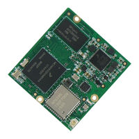
Compute Module with NXP i.MX6Ultralite SoC
Brand:
TechNexion
| Category:
Control Unit
| Size: 1 MB
Table of Contents
Table of Contents
3
1 Introduction
7
General Introduction
7
General Care and Maintenance
8
Block Diagram
10
Figure 1 - PICO-IMX6UL-EMMC Block Diagram
10
PICO Compute Module Compatibility
11
Table 1 - PICO Compatibility Overview
11
Figure 2 - PICO-IMX6UL-EMMC Compatibility Chart
11
Dimensional Drawing
12
Figure 3 - PICO-IMX6UL-EMMC Dimensional Drawing
12
Component Location
13
Figure 4 - PICO-IMX6UL-EMMC Top View
13
Figure 5 - PICO-IMX6UL-EMMC Bottom View
13
2 Core Components
14
NXP I.mx6Ultralite Cortex-A7 Processor
14
Figure 6 - NXP I.mx6Ultralite Processor Blocks
14
Power Management IC (NXP PF3000)
15
NXP PF3000 Reset Signal
15
Table 2 - PMIC Signal Description
15
Table 3 - PMIC Reset Signal Description
15
Table 4 - PMIC Reset Signal Description
15
Memory
16
Hynix
16
Micron
17
Emmc Storage
18
Sandisk Inand
18
Kingston EMMC
19
Table 5 - Emmc Signal Description
20
Broadcom BCM4339 Wifi/Bluetooth Sip Module
21
Figure 7 - PICO-IMX6UL-EMMC Antenna U.fl Connector Location
21
Table 6 - BCM4339 Wifi Signal Description
22
Table 7 - BCM4339 Bluetooth Signal Description
23
3 PICO Compute Module Connector Interfaces
24
Ethernet
24
Table 8 - Ethernet Signal Description
24
Digital Display Sub-System (DSS) or TTL Interface
25
Table 9 - TTL Display Signal Description
26
Audio Interface
27
Table 10 - I S Audio Signal Description
27
Universal Serial Bus (USB) Interface
28
Table 11 - USB Host Signal Description
28
Table 12 - USB OTG Signal Description
28
CAN BUS Interface Signals
29
Table 13 - CAN Bus Signal Description
29
Universal Asynchronous Receiver/Transmitter (UART) Interface
30
Table 14 - UART Signal Description
30
Serial Peripheral Interface (SPI)
31
Table 15 - SPI Channel Signal Description
31
I 2 C Bus
32
Table 16 - I C Bus Signal Description
32
General Purpose Input/Output (GPIO)
33
Table 17 - GPIO Signal Description
33
Pulse Width Modulation (PWM)
34
Table 18 - PWM Signal Description
34
Manufacturing and Boot Control
35
Boot Modes
35
Table 19 - Boot Selection Pins
35
Table 20 - Serial Downloader Boot Mode Configuration
35
Table 21 - Internal Downloader Boot Mode Configuration
35
Input Power Requirements
36
Power Management Signals
36
Table 22 - Input Power Signals
36
Table 23 - Power Management Signals
36
Power Sequence
37
Table 24 - Input Power Sequencing for at Based Configurations
37
Figure 8 - Input Power Sequence for at Based Configurations
37
4 PICO Compute Module Pin Assignment
38
5 PICO Compute Module Pinmux Overview
45
6 Development Kits, Proto-Type Components and Accessories
48
PICO-IMX6UL-EMMC Evaluation Kits
48
PICO Evaluation Start Kit Pack Content
48
PICO Compatible Displays
49
Multi Touch PCAP Displays
49
Accessories
50
EDMANTP150A138045D2450BK Pack Content
50
PICO Compute Module Product Ordering Part Numbers
51
Standard Part Numbers
51
Custom Part Number Creation Rules
52
7 Important Notice
53
8 Disclaimer
54
Advertisement
Advertisement
Related Products
TechNexion PICO-IMX6
TechNexion PICO-IMX8M
TechNexion EDM1-IMX6
TechNexion EDM1-IMX6PLUS
TechNexion FLEX-IMX8M-Mini
TechNexion TAM-3517
TechNexion Categories
Motherboard
Control Unit
Desktop
Touch Panel
Single board computers
More TechNexion Manuals
Login
Sign In
OR
Sign in with Facebook
Sign in with Google
Upload manual
Upload from disk
Upload from URL