Sign In
Upload
Manuals
Brands
TechNexion Manuals
Control Unit
EDM1-IMX6
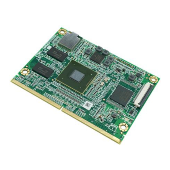
TechNexion EDM1-IMX6 System-on-Module Manuals
Manuals and User Guides for TechNexion EDM1-IMX6 System-on-Module. We have
1
TechNexion EDM1-IMX6 System-on-Module manual available for free PDF download: Manual
TechNexion EDM1-IMX6 Manual (80 pages)
Brand:
TechNexion
| Category:
Control Unit
| Size: 3 MB
Table of Contents
Table of Contents
3
Introduction
7
General Introduction
7
General Care and Maintenance
8
Block Diagram
10
EDM Compatibility
11
Table 1 - EDM Compatibility Overview
11
Figure 2 - EDM Type 1 Compatibility Chart
11
Dimensional Drawing
12
Figure 3 - EDM1-IMX6 Dimensional Drawing
12
Component Location
13
Figure 4 - EDM1-IMX6 Top View
13
Figure 5 - EDM1-IMX6 Bottom View
13
Core Components
14
NXP I.mx6 Cortex-A9 Multi-Core Processor
14
Figure 6 - NXP I.mx6 Processor Blocks
14
Figure 7 - NXP I.mx6 Processor Scalability Overview (Solo/Duallite/Dual/Quad/Quadplus)
15
I.mx6 Memory Interfaces
16
I.mx6 DMA Engine
16
I.mx6 Video and Graphics Subsystems
17
Power Management IC (MMPF0100)
18
Table 2 - PMIC Signal Description
18
Memory
19
Emmc Storage
20
Table 3 - Emmc Signal Description
20
Figure 8 - Emmc Schematics
21
Wifi/Bluetooth SIP Module
22
Figure 9 - EDM1-IMX6 Wi-Fi Module and Antenna Connector Location
22
Table 4 - Wi-Fi Signal Description
23
Table 5 - Bluetooth Signal Description
24
Atheros AR8035 Gigabit LAN
25
Table 6 - Gigabit Ethernet Interconnect between I.mx6 and AR8035
26
Table 7 - EDM Gigabit Ethernet Signal Description
26
Gigabit Ethernet Magnetics
27
Figure 10 - Gigabit Ethernet Schematics
28
MIPI Camera and Display Connector
29
MIPI Camera
29
MIPI Display
30
Table 8 - MIPI Display and Camera Expansion Connector Signal Description
30
JTAG Connector
32
Table 9 - JTAG Expansion Header Signal Description
32
EDM Type 1 Connector Interfaces
33
Gigabit Ethernet
33
Table 10 - EDM Gigabit Ethernet Signal Description
33
LVDS Interface
34
Table 11 - LVDS Signal Description
35
Table 12 - LVDS Panel Detection Pins
35
HDMI (High Definition Multi-Media Interface)
36
Table 13 - HDMI Signal Description
36
Digital Display Sub-System (DSS) or TTL Interface
37
Table 14 - TTL Display Signal Description
38
Audio Interface
39
Table 15 - Primary I
40
Table 16 - Secondary I
40
S/P DIF Audio
41
Table 17 - S/P DIF Audio Signal Description
41
PCI Express
42
Table 18 - PCI Express Signal Description
42
Serial ATA Interface
43
Table 19 - Serial ATA Signal Description
43
Universal Serial Bus (USB) Interface
44
Table 20 - USB Host Signal Description
45
Table 21 - USB OTG Signal Description
45
SDIO/MMC Interface
46
Table 22 - SDIO/MMC Interface Signal Description
46
General Purpose Memory Controller Bus (Local Bus)
47
Table 23 - GPMC / Local Bus Signal Description
48
CAN BUS Interface Signals
49
Table 24 - Primary CAN Bus Signal Description
49
Table 25 - Secondary CAN Bus Signal Description
49
Universal Asynchronous Receiver/Transmitter (UART) Interface
50
Table 26 - Primary UART Signal Description
50
Table 27 - Secondary UART Signal Description
51
Serial Peripheral Interface (SPI)
52
Table 28 - Primary SPI Channel Signal Description
52
Table 29 - Secondary SPI Channel Signal Description
53
I 2 C Bus
54
Display and System Management Purpose I
54
Bus
54
Table 30 - Display and System Management Purpose I
54
General Purpose I C Bus
55
Table 31 - Primary General Purpose I
55
Table 32 - Secondary General Purpose I
55
General Purpose Input/Output (GPIO)
56
Table 33 - GPIO Signal Description
56
Manufacturing and Boot Control
57
Table 34 - EDM MNF Pin Description
57
Table 35 - EDM MNF Boot Configuration Option Overview
57
Table 36 - EDM-MNF-BOOT Configuration for EDM1-FAIRY
58
Figure 11 - EDM1-FAIRY with EDM-MNF-BOOT
58
Input Power Requirements
59
Power Management Signals
59
Table 37 - Input Power Signals
59
Power Sequencing for at Based Configurations
60
Table 38 - Input Power Sequencing for at Based Configurations
60
Figure 12 - Input Power Sequence for at Based Configurations
60
Power Sequencing for ATX Based Configurations
61
Table 39 - Input Power Sequencing for ATX Based Configurations
61
Figure 13 - Input Power Sequence for ATX Based Configurations
61
EDM1-IMX6 Power Option Without Carrier Board
62
Figure 14 - EDM1-IMX6 Optional Power Connector Location
62
Figure 15 - EDM1-IMX6 with Mounted Molex 43650-0200 Connector
62
EDM Connector Pin Assignment
63
EDM Pinmux Overview
74
Ordering Information, Evaluation Components and Accessories
77
Product Ordering Part Numbers
77
Standard Part Numbers
77
Custom Part Number Creation Rules
78
Important Notice
79
Disclaimer
80
Advertisement
Advertisement
Related Products
TechNexion EDM1-IMX6PLUS
TechNexion FLEX-IMX8M-Mini
TechNexion PICO-IMX6
TechNexion PICO-IMX6UL-EMMC
TechNexion PICO-IMX8M
TechNexion TAM-3517
TechNexion Categories
Motherboard
Control Unit
Desktop
Touch Panel
Single board computers
More TechNexion Manuals
Login
Sign In
OR
Sign in with Facebook
Sign in with Google
Upload manual
Upload from disk
Upload from URL