Sign In
Upload
Manuals
Brands
Supero Manuals
Motherboard
X10SRL-F
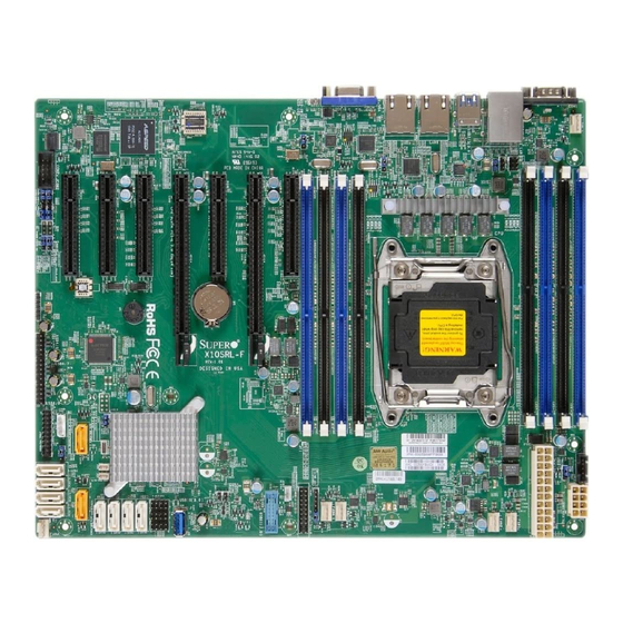
Supero X10SRL-F Manuals
Manuals and User Guides for Supero X10SRL-F. We have
2
Supero X10SRL-F manuals available for free PDF download: User Manual
Supero X10SRL-F User Manual (133 pages)
Brand:
Supero
| Category:
Motherboard
| Size: 12.2 MB
Table of Contents
About this Motherboard
3
Manual Organization
3
Preface
3
Conventions Used in the Manual
4
Contacting Supermicro
5
Table of Contents
6
Chapter 1 Introduction
15
Overview
15
Checklist
15
Jumper Description
18
Motherboard Features
20
System Block Diagram
22
Chipset Overview
23
Intel C612 Express Chipset Features
23
Special Features
24
Recovery from AC Power Loss
24
PC Health Monitoring
24
Environmental Temperature Control
24
System Resource Alert
24
ACPI Features
25
Slow Blinking LED for Suspend-State Indicator
25
Power Supply
25
Super I/O
26
Chapter 2 Installation
27
Standardized Warning Statements
27
Battery Handling
27
Product Disposal
29
Static-Sensitive Devices
30
Precautions
30
Unpacking
30
Motherboard Installation
31
Tools Needed
31
Location of Mounting Holes
31
Installing the Motherboard
32
Processor and Heatsink Installation
33
Installing the LGA2011 Processor
33
Installing a Passive CPU Heatsink
37
Removing the Heatsink
38
Installing DDR4 Memory
39
DIMM Installation
39
Removing Memory Modules
40
Memory Support
40
Memory Population Guidelines
40
Connectors/Io Ports
43
Backplane I/O Panel
43
Universal Serial Bus (USB)
44
Ethernet Ports
45
Serial Ports (COM1/COM2)
45
Unit Identifier Switch/Uid LED Indicator
46
VGA Port
46
Front Control Panel
47
Front Control Panel Pin Definitions
48
NMI Button
48
Power LED
48
Hdd Led
49
NIC1/NIC2 Leds
49
Overheat (Oh)/Fan Fail/Pwr Fail/Uid LED
50
Power Fail LED
50
Power Button
51
Reset Button
51
Connecting Cables
52
ATX Main PWR & CPU PWR Connectors (J24 & JPWR1)
52
Fan Headers (Fan 1-Fan 5 & Fan a )
53
Chassis Intrusion (JL1)
53
Internal Speaker/Buzzer (SP1)
54
Overheat (Oh)/Fan Fail
54
DOM PWR Connector (JSD1)
55
Standby Power
55
T-SGPIO 1/2/3 Headers
56
Power SMB (I C) Connector
56
TPM Header/Port 80 Header
57
Video Connector
57
Jumper Settings
58
Explanation of Jumpers
58
LAN1/LAN2 Enable/Disable
58
CMOS Clear (JBT1)
59
PCI-E Slot SMB Enable (I C1/I C2)
59
Manufacture Mode Select
60
VGA Enable
60
Watch Dog Enable/Disable
61
Onboard Indicators
62
LAN 1/LAN 2 Leds
62
IPMI Dedicated LAN Leds
62
Onboard Power LED (LE2)
63
BMC Heartbeat LED (LEDM1)
63
2-10 SATA Connections
64
Chapter 3 Troubleshooting
65
Troubleshooting Procedures
65
Before Power on
65
No Power
65
No Video
66
Memory Errors
66
Losing the System's Setup Configuration
66
Technical Support Procedures
67
Frequently Asked Questions
68
Battery Removal and Installation
69
Battery Removal
69
Proper Battery Disposal
69
Battery Installation
69
Returning Merchandise for Service
70
Chapter 4 BIOS
71
Introduction
71
Starting BIOS Setup Utility
71
How to Change the Configuration Data
71
How to Start the Setup Utility
72
Main Setup
72
The Following Main Menu Items will be Displayed
72
System Date/System Time
73
Supermicro X10SRL-F
73
BIOS Version: this Item Displays the Version of the BIOS ROM Used in the System
73
Build Date: this Item Displays the Date When the Version of the BIOS ROM Used in the System was Built
73
Memory Information
73
Memory Speed: this Item Displays the Default Speed of the Memory Modules Installed in the System
73
Total Memory: this Item Displays the Total Size of Memory Available in the System
73
Advanced Setup Configurations
74
Boot Feature
74
Addon ROM Display Mode
74
Bootup Num-Lock
74
Quiet Boot
74
INT19 (Interrupt 19) Trap Response
75
Re-Try Boot
75
Wait for 'F1' if Error
75
Power Configuration
75
Deepsx Power Policies
75
Power Button Function
75
Watch Dog Function
75
Clock Spread Spectrum
76
CPU Configuration
76
Restore on AC Power Loss
76
Adjacent Cache Line Prefetch (Available When Supported by the CPU)
77
Cores Enabled
77
DCU Streamer Prefetcher (Available When Supported by the CPU)
77
Execute Disable Bit (Available if Supported by the os & the CPU)
77
Hardware Prefetcher (Available When Supported by the CPU)
77
Hyper-Threading (ALL)
77
PPIN Control
77
Aes-Ni
78
DCA Prefetch Delay
78
DCU (Data Cache Unit) Mode
78
DCU IP Prefetcher
78
Direct Cache Access (DCA)
78
Intel Virtualization Technology
78
X2APIC (Extended Advanced Programmable Interrupt Controller)
78
Advanced Power Management Configuration
79
Chipset Configuration
82
North Bridge
82
IIO Configuration
82
Intel VT for Directed I/O (VT-D)
83
QPI (Quick Path Interconnect) Configuration
84
Memory Configuration
85
DIMM Information
86
EHCI Hand-Off
88
Ehci1
88
Legacy USB Support
88
Port 60/64 Emulation
88
South Bridge
88
USB 3.0 Support
88
USB Mass Storage Driver Support
88
XHCI Hand-Off
88
Configure SATA as
89
Ehci2
89
Pch DMI Aspm
89
SATA Configuration
89
SATA Controller
89
XHCI Idle L1
89
XHCI Pre-Boot Driver
89
If the Item above "Configure SATA As" Is Set to IDE, the Following Items will Display
90
If the Item above "Configure SATA As" Is Set to RAID, the Following Items will Display
91
Configure Ssata as
92
Ssata Configuration
92
Ssata Controller
92
If the Item above "Configure Ssata As" Is Set to IDE, the Following Items will Display
93
If the Item above "Configure Ssata As" Is Set to RAID, the Following Items will Display
93
Server ME (Management Engine) Configuration
94
Pcie/Pci/Pnp Configuration
95
Above 4G Decoding (Available if the System Supports 64-Bit PCI Decoding)
95
ASPM Support
95
Maximum Payload
95
Maximum Read Request
95
PCI AER (Advanced Error-Reporting) Support
95
SR-IOV Support (Available if the System Supports Single-Root Virtualization)
95
The Following PCI Information will be Displayed
95
VGA Palette Snoop
95
MMIO High Size
96
Mmiohbase
96
Network Stack
96
Onboard LAN Option ROM Type
96
Onboard LAN1 Option Rom/Onboard LAN2 Option ROM
96
Onboard Video Option ROM
96
VGA Priority
96
Super IO Configuration
97
Change Port 1 Settings/Change Port 2 Settings
97
Device Settings
97
Serial Port 1 Configuration/Serial Port 2 Configuration
97
Serial Port 1/Serial Port 2
97
Serial Port 2 Attribute
97
Serial Port Console Redirection
97
COM 1 Console Redirection
97
COM1 Console Redirection Settings
98
Sol/Com2
99
SOL/COM2 Console Redirection
99
SOL/COM2 Console Redirection Settings
99
Serial Port for Out-Of-Band Management/Windows Emergency Management Services (EMS)
101
EMS (Emergency Management Services) Console Redirection
101
EMS Console Redirection Settings
101
Trusted Computing (Available When a TPM Device Is Installed and Detected by the BIOS)
102
Configuration
102
Security Device Support
102
TPM State
102
Pending Operation
102
Current Status Information
102
ACPI Settings
103
High Precision Timer
103
Numa
103
WHEA Support
103
Event Logs
104
Change SMBIOS Event Log Settings
104
Enabling/Disabling Options
104
Memory Corrected Error Enabling (Available When the Item Above-Runtime Error Logging Support Is Set to Enable)
104
PCI-Ex (PCI-Express) Error Enable
104
Runtime Error Logging Support
104
SMBIOS Event Log
104
Erase Event Log
105
Erasing Settings
105
Log System Boot Event
105
MECI (Multiple Event Count Increment)
105
Memory Correctable Error Threshold
105
METW (Multiple Event Count Time Window)
105
SMBIOS Event Log Standard Settings
105
View System Event Log
105
When Log Is Full
105
Ipmi
106
IPMI Firmware Revision
106
IPMI Status
106
System Event Log
106
Enabling/Disabling Options
106
Erase SEL
106
Erasing Settings
106
SEL Components
106
BMC Network Configuration
107
Configuration Address Source
107
IPMI LAN Selection
107
IPMI Network Link Status
107
Update IPMI LAN Configuration
107
When SEL Is Full
107
Security
109
Password Check
109
Administrator Password
109
Boot
110
Setup Prompt Timeout
110
Boot Mode Select
110
Fixed Boot Order Priorities
110
Delete Boot Option
111
Hard Disk Drive BBS Priorities
111
Network Drive BBS Priorities
111
UEFI Application Boot Priorities
111
Save & Exit
112
Discard Changes and Exit
112
Save Changes and Reset
112
Save Options
112
Save Changes
112
Discard Changes
112
Restore Defaults
112
Save as User Defaults
113
Restore User Defaults
113
Boot Override
113
Appendix A BIOS Error Beep Codes
115
A-1 BIOS Error Beep Codes
115
Appendix B Software Installation Instructions
117
B-1 Installing Software Programs
117
B-2 Installing Superdoctor5
118
Appendix C UEFI BIOS Recovery Instructions
119
C-1 an Overview to the UEFI BIOS
119
C-2 How to Recover the UEFI BIOS Image
119
To Recover the Main BIOS Block Using a USB-Attached Device
119
Appendix D Dual Boot Block on Grantley Platforms
123
Overview
123
Before Startup
123
When to Use Dual Boot Block
123
How to Use Dual Boot Block
123
D-1 IPMI GUI Browser
124
D-2 IPMI Command Sets
129
User Approach
131
Advertisement
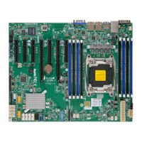
Supero X10SRL-F User Manual (129 pages)
Brand:
Supero
| Category:
Motherboard
| Size: 11.46 MB
Table of Contents
About this Motherboard
3
Manual Organization
3
Preface
3
Conventions Used in the Manual
4
Contacting Supermicro
5
Table of Contents
6
Chapter 1 Introduction
15
Overview
15
Checklist
15
Motherboard Features
20
System Block Diagram
22
Chipset Overview
23
Intel ® C612 Express Chipset Features
23
Special Features
24
Recovery from AC Power Loss
24
PC Health Monitoring
24
Environmental Temperature Control
24
System Resource Alert
24
ACPI Features
25
Slow Blinking LED for Suspend-State Indicator
25
Power Supply
25
Chapter 2 Installation
27
Standardized Warning Statements
27
Battery Handling
27
Product Disposal
29
Static-Sensitive Devices
30
Precautions
30
Unpacking
30
Motherboard Installation
31
Tools Needed
31
Location of Mounting Holes
31
Installing the Motherboard
32
Processor and Heatsink Installation
33
Installing the LGA2011 Processor
33
Installing a Passive CPU Heatsink
37
Removing the Heatsink
38
Installing DDR4 Memory
39
Installing Memory Modules
39
Removing Memory Modules
40
Memory Support
40
Memory Population Guidelines
40
Connectors/Io Ports
43
Backplane I/O Panel
43
Universal Serial Bus (USB)
44
Ethernet Ports
45
Serial Ports (COM1/COM2)
45
Unit Identifier Switch/Uid LED Indicator
46
VGA Port
46
Front Control Panel
47
Front Control Panel Pin Definitions
48
NMI Button
48
Power LED
48
Hdd Led
49
NIC1/NIC2 Leds
49
Overheat (Oh)/Fan Fail/Pwr Fail/Uid LED
50
Power Fail LED
50
Power Button
51
Reset Button
51
Connecting Cables
52
ATX Main PWR & CPU PWR Connectors (J24 & JPWR1)
52
Fan Headers (Fan 1-Fan 5 & Fan a )
53
Chassis Intrusion
53
Internal Speaker/Buzzer
54
Overheat (Oh)/Fan Fail
54
DOM PWR Connector
55
Standby Power
55
T-SGPIO 1/2/3 Headers
56
Power SMB (I C) Connector
56
TPM Header/Port 80 Header
57
Video Connector
57
Jumper Settings
58
Explanation of Jumpers
58
LAN1/LAN2 Enable/Disable
58
CMOS Clear
59
PCI-E Slot SMB Enable
59
Manufacture Mode Select
60
VGA Enable
60
BIOS Recovery Enable
61
Watch Dog Enable/Disable
61
BMC Enable/Disable (JPB1)
62
Onboard Indicators
63
LAN 1/LAN 2 Leds
63
IPMI Dedicated LAN Leds
63
Onboard Power LED
64
BMC Heartbeat LED
64
2-10 SATA Connections
65
Chapter 3 Troubleshooting
67
Troubleshooting Procedures
67
Before Power on
67
No Power
67
No Video
68
Memory Errors
68
Losing the System's Setup Configuration
68
Technical Support Procedures
69
Frequently Asked Questions
70
Battery Removal and Installation
71
Battery Removal
71
Proper Battery Disposal
71
Battery Installation
71
Returning Merchandise for Service
72
Chapter 4 BIOS
73
Introduction
73
Starting BIOS Setup Utility
73
How to Change the Configuration Data
73
How to Start the Setup Utility
74
Main Setup
74
The Following Main Menu Items will be Displayed
75
System Date/System Time
75
Supermicro X10SRL-F
75
BIOS Version: this Item Displays the Version of the BIOS ROM Used in the System
75
Build Date: this Item Displays the Date When the Version of the BIOS ROM Used in the System was Built
75
Memory Information
75
Memory Speed: this Item Displays the Default Speed of the Memory Modules Installed in the System
75
Total Memory: this Item Displays the Total Size of Memory Available in the System
75
Advanced Setup Configurations
76
Boot Feature
76
Addon ROM Display Mode
76
Bootup Num-Lock
76
Quiet Boot
76
INT19 (Interrupt 19) Trap Response
77
Re-Try Boot
77
Wait for 'F1' if Error
77
Power Configuration
77
Power Button Function
77
Restore on AC Power Loss
77
Watch Dog Function
77
Clock Spread Spectrum
78
Cores Enabled
78
CPU Configuration
78
Hyper-Threading (ALL)
78
Adjacent Cache Line Prefetch (Available When Supported by the CPU)
79
DCU IP Prefetcher
79
DCU Streamer Prefetcher (Available When Supported by the CPU)
79
Direct Cache Access (DCA)
79
Execute Disable Bit (Available if Supported by the os & the CPU)
79
Hardware Prefetcher (Available When Supported by the CPU)
79
PPIN Control
79
Aes-Ni
80
Intel Virtualization Technology
80
X2APIC (Extended Advanced Programmable Interrupt Controller)
80
Advanced Power Management Configuration
80
Ioat Configuration
82
Chipset Configuration
82
North Bridge
82
IIO Configuration
82
Intel VT for Directed I/O (VT-D)
83
QPI (Quick Path Interconnect) Configuration
83
Memory Configuration
84
DIMM Information
85
South Bridge
87
Legacy USB Support
87
EHCI Hand-Off
87
Ehci1
87
Ehci2
87
Port 60/64 Emulation
87
USB 3.0 Support
87
XHCI Hand-Off
87
Configure SATA as
88
SATA Configuration
88
SATA Controller
88
XHCI Pre-Boot Driver
88
If the Item above "Configure SATA As" Is Set to IDE, the Following Items will Display
89
If the Item above "Configure SATA As" Is Set to RAID, the Following Items will Display
89
Configure Ssata as
90
Ssata Configuration
90
Ssata Controller
90
If the Item above "Configure Ssata As" Is Set to IDE, the Following Items will Display
91
If the Item above "Configure Ssata As" Is Set to RAID, the Following Items will Display
91
Server ME (Management Engine) Configuration
92
Pcie/Pci/Pnp Configuration
92
The Following PCI Information will be Displayed
92
Above 4G Decoding (Available if the System Supports 64-Bit PCI Decoding)
93
ASPM Support
93
Maximum Payload
93
Maximum Read Request
93
MMIO High Size
93
Mmiohbase
93
PCI PERR/SERR Support
93
SR-IOV Support (Available if the System Supports Single-Root Virtualization)
93
Change Port 1 Settings/Change Port 2 Settings
94
Device Settings
94
Network Stack
94
Onboard LAN Option ROM Type
94
Onboard LAN1 Option Rom/Onboard LAN2 Option ROM
94
Onboard Video Option ROM
94
Serial Port 1 Configuration/Serial Port 2 Configuration
94
Serial Port 1/Serial Port 2
94
Super IO Configuration
94
VGA Priority
94
COM 1 Console Redirection
95
Serial Port 2 Attribute
95
Serial Port Console Redirection
95
COM1 Console Redirection Settings
95
Sol/Com2
97
SOL/COM2 Console Redirection
97
SOL/COM2 Console Redirection Settings
97
EMS (Emergency Management Services) Console Redirection
99
EMS Console Redirection Settings
99
Serial Port for Out-Of-Band Management/Windows Emergency Management Services (EMS)
99
ACPI Settings
100
High Precision Timer
100
PCI AER (Advanced Error-Reporting) Support
100
WHEA Support
100
Event Logs
101
Change SMBIOS Event Log Settings
101
Enabling/Disabling Options
101
Memory Correctable Error Threshold
101
Memory Corrected Error Enabling (Available When the Item Above-Runtime Error Logging Support Is Set to Enable)
101
PCI-Ex (PCI-Express) Error Enable
101
Runtime Error Logging Support
101
SMBIOS Event Log
101
Erase Event Log
102
Erasing Settings
102
Log System Boot Event
102
MECI (Multiple Event Count Increment)
102
METW (Multiple Event Count Time Window)
102
SMBIOS Event Log Standard Settings
102
View System Event Log
102
When Log Is Full
102
Ipmi
103
IPMI Firmware Revision
103
IPMI Status
103
System Event Log
103
Enabling/Disabling Options
103
Erase SEL
103
Erasing Settings
103
SEL Components
103
BMC Network Configuration
104
Configuration Address Source
104
IPMI LAN Selection
104
IPMI Network Link Status
104
Update IPMI LAN Configuration
104
When SEL Is Full
104
Security
106
Password Check
106
Administrator Password
106
Boot
107
Setup Prompt Timeout
107
Boot Mode Select
107
Fixed Boot Order Priorities
107
Delete Boot Option
108
UEFI Application Boot Priorities
108
Save & Exit
109
Discard Changes and Exit
109
Save Changes and Reset
109
Save Options
109
Save Changes
109
Discard Changes
109
Restore Optimized Defaults
110
Save as User Defaults
110
Restore User Defaults
110
Boot Override
110
Appendix A BIOS Error Beep Codes
111
A-1 BIOS Error Beep Codes
111
Appendix B Software Installation Instructions
113
B-1 Installing Software Programs
113
B-2 Installing Superdoctor5
114
Appendix C UEFI BIOS Recovery Instructions
115
C-1 an Overview to the UEFI BIOS
115
C-2 How to Recover the UEFI BIOS Image
115
To Recover the Main BIOS Block Using a USB-Attached Device
115
Appendix D Dual Boot Block on Grantley Platforms
119
Overview
119
Before Startup
119
When to Use Dual Boot Block
119
How to Use Dual Boot Block
119
D-1 IPMI GUI Browser
120
D-2 IPMI Command Sets
125
User Approach
127
Advertisement
Related Products
Supero X10SRH-CF
Supero X10SRA-F
Supero X10SRA
Supero X10SRi-F
Supero X10SRH-CLN4F
Supero X10SRW-F
Supero X10SLQ
Supero X10SLL-SF
Supero X10SLE-HF
Supero X10SLL-F
Supero Categories
Motherboard
Server
Chassis
Computer Hardware
Desktop
More Supero Manuals
Login
Sign In
OR
Sign in with Facebook
Sign in with Google
Upload manual
Upload from disk
Upload from URL