Sign In
Upload
Manuals
Brands
Sun Microsystems Manuals
Server
Fire X4600
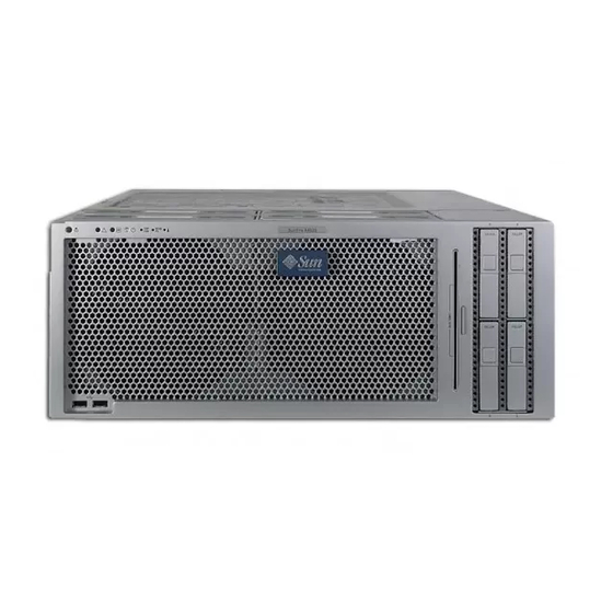
Sun Microsystems Fire X4600 Manuals
Manuals and User Guides for Sun Microsystems Fire X4600. We have
3
Sun Microsystems Fire X4600 manuals available for free PDF download: Service Manual, Installation Manual, Manual
Sun Microsystems Fire X4600 Service Manual (234 pages)
Brand:
Sun Microsystems
| Category:
Server
| Size: 9 MB
Table of Contents
Table of Contents
3
Preface
17
Related Documentation
18
Web Sites
19
Sun Welcomes Your Comments
19
1 Introduction to the Sun Fire X4600/X4600 M2 Servers
21
Features of the Server
21
TABLE 1-1 Summary of Features
22
Sun Fire X4600/X4600 M2 Features and Components
24
Sun Fire X4600/X4600 M2 Servers Front Panel Features
24
FIGURE 1-1 Sun Fire X4600/X4600 M2 Servers Front Panel Features
24
Sun Fire X4600/X4600 M2 Servers Back Panel Features
25
FIGURE 1-2 Sun Fire X4600/X4600 M2 Servers Back Panel
25
Sun Fire X4600/X4600 M2 Servers Components
26
FIGURE 1-3 Sun Fire X4600/X4600 M2 Replaceable Component Locations
26
Accessory Kits
27
Additional Options and Replaceable Components
27
TABLE 1-2 Sun Fire X4600/X4600 M2 Accessory Kit
27
2 Powering on and Configuring BIOS Settings
29
Powering on the Server
29
FIGURE 2-1 Sun Fire X4600/X4600 M2 Servers Front Panel
30
Powering off the Server
31
Configuring BIOS Settings
31
Changing the Configuration of a BIOS Menu Item
32
BIOS Considerations
32
Device Booting Detection Priority
32
Ethernet Port (NIC) Device and Driver Naming
33
FIGURE 2-2 Ethernet Port Chassis Labeling Designations
33
FIGURE 2-3 Sun Fire X4600 NIC Naming
34
BIOS Option ROM Size Limitation
35
Descriptions of the BIOS Setup Utility Screens
35
TABLE 2-1 BIOS Setup Screens Summary
36
FIGURE 2-5 BIOS Setup Utility Menu Tree
37
BIOS Setup Utility Menu Screens
38
BIOS Main Menu Screen
38
BIOS Advanced Menu, Main Screen
39
BIOS Advanced Menu, CPU Configuration Screen
41
BIOS Advanced Menu, IDE Configuration Screen
42
BIOS Advanced Menu, Superio Chipset Configuration Screen
43
BIOS Advanced Menu, ACPI Configuration Screen
43
BIOS Advanced Menu, Advanced ACPI Configuration Screen
44
BIOS Advanced Menu, Event Logging Details Screen
44
BIOS Advanced Menu, Powernow Configuration
45
BIOS Advanced Menu, Hypertransport Configuration Screen
46
BIOS Advanced Menu, IPMI 2.0 Configuration Screen
48
BIOS Advanced Menu, IPMI 2.0, View BMC Event Log Screen
48
BIOS Advanced Menu, IPMI 2.0, LAN Configuration Screen
49
BIOS Advanced Menu, IPMI 2.0, PEF Configuration Screen
50
BIOS Advanced Menu, MPS Configuration Screen
51
BIOS Advanced Menu, PCI Express Configuration Screen
51
BIOS Advanced Menu, Remote Access Configuration Screen
52
BIOS Advanced Menu, USB Configuration Screen
53
BIOS Pci/Pnp Menu
55
BIOS Boot Menu, Main Screen
57
BIOS Boot Menu, Boot Settings Configuration Screen
57
BIOS Boot Menu, Boot Device Priority Screen
58
BIOS Boot Menu, Hard Disk Drives Screen
58
BIOS Boot Menu, Removable Drives Screen
59
BIOS Boot Menu, CD/DVD Drives Screen
59
BIOS Security Settings Menu
60
BIOS Chipset Menu, Main Screen
60
BIOS Chipset Menu, Northbridge Configuration Screen
61
Configuration Screen
63
BIOS Chipset Menu, Northbridge ECC Configuration Screen
64
BIOS Chipset Menu, Southbridge Configuration Screen
65
BIOS Exit Options Menu Screen
66
Resetting SP and BIOS Passwords Using Jumper P20
67
FIGURE 2-6 Location of Jumpers on the Motherboard
69
Using the Force-Recovery Jumper P19
70
Using the Clear CMOS Jumper P25
71
Using the Reset and NMI Dump Switches
72
FIGURE 2-7 Sun Fire X4600/X4600 M2 Servers Back Panel
72
Updating the BIOS
73
Power-On Self-Test (POST)
73
3 Maintaining the Sun Fire X4600/X4600 M2 Servers
75
Tools and Supplies Needed
75
Powering off and Removing the Covers
76
Powering off the Server
76
FIGURE 3-1 Sun Fire X4600/X4600 M2 Servers Front Panel
77
Removing the Main Cover
78
FIGURE 3-2 Removing the Main Cover
78
Removing the Front Bezel
79
FIGURE 3-3 Removing the Front Bezel
79
Locations of the Sun Fire X4600/X4600 M2 Components
80
FIGURE 3-4 Sun Fire X4600/X4600 M2 Replaceable Component Locations
80
Replaceable Component Procedures
81
Replacing the Battery
82
FIGURE 3-5 Removing the Battery
83
Replacing a CPU Module or CPU Filler Board
84
CPU Module Slot Lettering and Numbering Designations
85
FIGURE 3-6 CPU Module Physical Slot Lettering and Internal Numbering Designation
85
CPU Module Fault Leds
86
FIGURE 3-7 Sun Fire X4600/X4600 M2 Designation of Physical CPU Module Slots
86
FIGURE 3-8 Sun Fire X4600 CPU Module LED and Button Locations
87
FIGURE 3-9 Sun Fire X4600 M2 CPU Module LED and Button Locations
88
FIGURE 3-10 Removing a CPU Module from a CPU Module Bay
89
Replacing the DVD-ROM Drive
91
FIGURE 3-11 Installing a CPU Module
91
FIGURE 3-12 Removing the DVD Drive
92
Replacing a Fan Tray
93
FIGURE 3-13 System Designation of Fan Trays
94
Replacing the Front Panel Indicator Board
95
FIGURE 3-14 Removing a Fan Tray
95
FIGURE 3-15 Removing the Fan Tray Carriage
97
FIGURE 3-16 Removing the Front Panel Indicator Board
98
Replacing the Front I/O Board
99
Replacing the GRASP Board
103
FIGURE 3-18 Removing the GRASP Board
104
Servicetool FRU Update Procedure
105
Replacing a Hard Disk Drive
106
FIGURE 3-19 Sun Fire X4600/X4600 M2 Designation of Hard Disk Drives
106
Replacing a Hard Disk Drive Backplane
108
FIGURE 3-20 Opening the Hard Disk Drive Latch
108
FIGURE 3-21 Removing the HDD Backplane
111
Replacing Memory Modules (Dimms)
112
FIGURE 3-22 Sun Fire X4600 Designation of DIMM Slots and Fault Leds on CPU Module
114
FIGURE 3-23 Sun Fire X4600 M2 Designation of DIMM Slots and Fault Leds on CPU Module
114
DIMM Population Rules
115
TABLE 3-1 Supported Sun Fire X4600 DIMM Configurations
115
TABLE 3-2 Supported Sun Fire X4600 M2 DIMM Configurations
116
FIGURE 3-24 Removing a DIMM
117
Replacing the Motherboard
118
FIGURE 3-25 Removing Rear CPU Module Guide
120
FIGURE 3-26 Motherboard Flex Cable Connectors and Bus Bar Screw Locations
121
FIGURE 3-27 Removing the Motherboard
122
Servicetool FRU Update Procedure
125
Replacing PCI Cards
126
FIGURE 3-28 Sun Fire X4600/X4600 M2 Locations, Designations, and Speeds of PCI Card Slots
128
Replacing a Power Supply
129
FIGURE 3-29 Opening the PCI Card Locking Lever and Removing the PCI Card
129
FIGURE 3-30 Sun Fire X4600/X4600 M2 Locations and Designations of Power Supplies
130
Power Supply Redundancy
130
Removing and Replacing a Power Supply
130
FIGURE 3-31 Removing a Power Supply
131
Replacing the Power Distribution Board
132
FIGURE 3-32 Disconnecting the Power Distribution Board from the Chassis
134
System Specifications
137
Sun Fire X4600/X4600 M2 Specifications
137
TABLE A-2 Sun Fire X4600/X4600 M2 Power Specifications
138
TABLE A-3 Sun Fire X4600/X4600 M2 Environmental Specifications
138
TABLE A-4 Sun Fire X4600/X4600 M2 Acoustic Noise Emission Specifications
139
BIOS POST Codes
141
Power-On Self-Test (POST
141
How BIOS POST Memory Testing Works
141
Redirecting Console Output
142
Changing POST Options
143
POST Codes
144
TABLE B-1 POST Codes
144
POST Code Checkpoints
146
TABLE B-2 POST Code Checkpoints
146
Status Indicator Leds
151
External Status Indicator Leds
151
FIGURE C-1 Sun Fire X4600/X4600 M2 Servers Front Panel Leds
152
TABLE C-1 Front Panel LED Functions
153
FIGURE C-2 Sun Fire X4600/X4600 M2 Servers Back Panel Leds
154
Internal Status Indicator Leds
156
FIGURE C-4 Sun Fire X4600 Fault LED and Button Locations on the CPU Module
156
FIGURE C-5 Sun Fire X4600/X4600 M2 GRASP Board LED Location
157
TABLE C-4 Internal LED Functions
158
Connector Pinouts
159
USB Connector
159
FIGURE D-1 USB Connector
159
TABLE D-1 USB Connector Pinouts
159
Serial Connector
160
10/100BASE-T Connector
160
FIGURE D-2 Serial Connector
160
TABLE D-2 Serial Connector Pinouts
160
10/100/1000BASE-T Connector
161
FIGURE D-3 10/100BASE-T Connector
161
FIGURE D-4 10/100/1000BASE-T Connector
161
TABLE D-3 10/100BASE-T Connector Pinouts
161
VGA Video Connector
162
FIGURE D-5 VGA Video Connector
162
TABLE D-4 10/100/1000BASE-T Connector Pinouts
162
TABLE D-5 VGA Video Connector Pinouts
162
TABLE D-6 Serial Attached SCSI Connector Pinouts
164
Serial Attached SCSI Connector
165
Flex Cable Motherboard Connector
165
FIGURE D-7 Flex Cable Motherboard Connector
166
TABLE D-7 Flex Cable Motherboard Connector Pinouts
166
Flex Cable Power Distribution Board Connector
170
FIGURE D-8 Flex Cable PDB Connector
170
TABLE D-8 Flex Cable PDB Connector Pinouts
171
Flex Cable DVD-ROM Drive Connector
172
FIGURE D-9 Flex Cable DVD-ROM Drive IDE Connector
172
TABLE D-9 Flex Cable DVD-ROM Drive IDE Connector Pinouts
172
Flex Cable HDD Backplane Connector
174
FIGURE D-10 Flex Cable HDD Backplane IDE Connector
174
TABLE D-10 Flex Cable HDD Backplane IDE Connector Pinouts
174
Motherboard Bus Bar Power Connectors
176
FIGURE D-11 Motherboard Bus Bar Connector
177
TABLE D-11 Motherboard Bus Bar Connector Pinouts
177
Front Flex Cable to Front I/O Board Connector
178
FIGURE D-12 Front Flex Cable to Front I/O Board Connector
178
TABLE D-12 Front Flex Cable to Front I/O Board Connector Pinouts
178
Front Flex Cable to Motherboard Connector
180
FIGURE D-13 Front Flex Cable to Motherboard Connector
180
TABLE D-13 Front Flex Cable to Motherboard Connector Pinouts
180
FIGURE D-14 Power Supply Connector
182
TABLE D-14 Power Supply Connector Pinouts
182
Power Supply Connector
183
Fan Module Connector
183
FIGURE D-15 Fan Module Connector
184
TABLE D-15 Fan Module Connector Pinouts
184
Serial Attached SCSI BIOS Configuration Utility
185
Fusion-MPT SAS BIOS Overview
185
Boot Initialization with BIOS Boot Specification (BBS
186
Starting the SAS BIOS Configuration Utility
186
Configuration Utility Screens
187
User Input Keys
188
Adapter List Screen
188
TABLE E-1 User Input Keys
188
FIGURE E-1 Adapter List Screen
189
TABLE E-2 Adapter List Screen Field Descriptions
190
Global Properties Screen
191
FIGURE E-2 Global Properties Screen
191
TABLE E-3 Global Properties Screen Field Descriptions
192
Adapter Properties Screen
193
FIGURE E-3 Adapter Properties Screen
193
TABLE E-4 Adapter Properties Screen Field Descriptions
194
SAS Topology Screen
195
FIGURE E-4 SAS Topology Screen
195
FIGURE E-5 SAS Topology Screen 2, Negotiated Link Speed
196
FIGURE E-6 SAS Topology Screen 3, Maximum Link Speed
197
FIGURE E-7 SAS Topology Screen 4, Target Capabilities
197
FIGURE E-8 SAS Topology Screen 5, Initiator Capabilities
198
TABLE E-5 SAS Topology Screens Field Descriptions
198
Device Properties Screen
200
FIGURE E-9 Device Properties Screen
200
Device Verify Screen
201
FIGURE E-10 Device Verify Screen
202
Advanced Adapter Properties Screen
203
FIGURE E-11 Advanced Adapter Properties Screen
203
TABLE E-8 Advanced Adapter Properties Screen Field Descriptions
204
Advanced Device Properties Screen
205
FIGURE E-12 Advanced Device Properties Screen
205
TABLE E-9 Advanced Device Properties Screen Field Descriptions
206
PHY Properties Screen
209
FIGURE E-13 PHY Properties Screen
209
TABLE E-10 PHY Properties Screen Field Descriptions
210
Integrated RAID Configuration and Management Screens
212
Select New Array Type Screen
212
FIGURE E-14 Select New Array Type Screen
212
Create New Array Screen
213
FIGURE E-15 Create New Array Screen
213
TABLE E-11 Create New Array Screen Field Descriptions
214
View Array Screen
216
FIGURE E-16 View Array Screen
216
TABLE E-12 View Array Screen Field Descriptions
218
Manage Array Screen
219
FIGURE E-17 Manage Array Screen
219
TABLE E-13 Manage Array Screen Field Descriptions
220
Exit Screen
221
FIGURE E-18 Exit Screen
221
Performing RAID Configuration Tasks
222
RAID Implementation and Support
222
Automatic Data Resynchronization and Hot Spares E
223
RAID Level Support
223
RAID Volume Support
224
RAID Combination Support
224
Creating a RAID 0 Volume
224
Creating a RAID 1 Volume
225
Creating a Second RAID Volume
226
Viewing RAID Volume Properties
227
Adding Hot Spares
227
Deleting Hot Spares
227
Synchronizing an Array
228
Activating an Array
228
Deleting an Array
228
Locating a Disk Drive
229
Advertisement
Sun Microsystems Fire X4600 Manual (52 pages)
Server Migration
Brand:
Sun Microsystems
| Category:
Server
| Size: 1 MB
Table of Contents
Table of Contents
3
Preface
11
Sun Fire X4600 to Sun Fire X4600 M2 Server Migration
13
Upgrade Procedure
13
Planning and Preparation
14
To Plan and Prepare
14
Populating a Server with CPU Modules
15
CPU Module Matching Requirements
15
Population Procedures
15
FIGURE 1 CPU Module Population Rules and Numbering
17
Interacting with the System
18
Interacting Directly
18
Interacting over the Network
19
Resetting SP and BIOS Passwords Using Jumper P20
20
To Reset the Administration Password Back to the Default
20
Powering off the Server
22
FIGURE 2 Location of Jumpers on the Motherboard
22
To Remove the Main Cover
23
FIGURE 3 Removing the Main Cover
24
To Replace the Cover
24
Accessing the Web GUI
25
FIGURE 4 ILOM Login Screen
25
Firmware: Planning and Downloading
26
FIGURE 5 Login to Redirected System Console
26
TABLE 1 Firmware Update Worksheet
27
To Upgrade the Firmware Images
27
TABLE 2 Firmware Update Example
28
To Replace the CPU Modules
29
To Replace a CPU Module or CPU Filler Board
30
FIGURE 6 Removing a CPU Module from a CPU Module Bay
31
FIGURE 7 Removing a DIMM
32
Updating the Firmware
34
FIGURE 8 Installing a CPU Module
34
To Update the ILOM and System BIOS
35
To Update from the ILOM Command Line
35
To Update from the Web Interface
35
Cleanup Steps, Post ILOM Update
36
To Perform the Cleanup Steps
36
Clearing CMOS Jumper P2
37
Forcing the ILOM Update
37
To Force the ILOM Update
37
Updating the LSI HBA BIOS
38
To Clear a Server's CMOS Settings with Jumper P2
38
To Update the LSI HBA BIOS
38
CPU Modules and Memory Dimms
39
CPU Module Models
39
Sun Fire X4600 CPU Module
40
Physical Layout
40
FIGURE 9 Physical Layout of Sun Fire X4600 CPU Module
41
DIMM Usage
42
TABLE 3 Sun Fire X4600 CPU Module Leds
42
TABLE 4 DIMM Slots in Sun Fire X4600 CPU Module
42
Sun Fire X4600 M2 4-DIMM CPU Module
43
Physical Layout
43
FIGURE 10 Physical Layout of Sun Fire X4600 M2 4-DIMM CPU Module X4600 M2
43
DIMM Usage
44
TABLE 5 Leds on Sun Fire X4600 M2 CPU 4-DIMM Module
44
Sun Fire X4600 M2 8-DIMM and 8-DIMM Split Plane CPU Modules
45
Physical Layout
45
TABLE 6 DIMM Slots in Sun Fire X4600 CPU Module
45
FIGURE 11 Physical Layout of Sun Fire X4600 M2 8-DIMM CPU Module and Sun Fire X4600 M2 8-DIMM Split Plane CPU Modules
46
TABLE 7 Leds on Sun Fire X4600 M2 CPU 4-DIMM Module
46
DIMM Usage
47
Populating a Server with CPU Modules
48
CPU Module Matching Requirements
48
Population Procedures
48
TABLE 8 Sun Fire X4600 M2 8-DIMM and 8-DIMM Split Plane CPU Module DIMM Slots
48
FIGURE 12 Sun Fire X4600/X4600 M2 CPU Module Slots
49
FIGURE 13 CPU Module Population Rules and Numbering
50
Sun Microsystems Fire X4600 Installation Manual (66 pages)
Brand:
Sun Microsystems
| Category:
Server
| Size: 3 MB
Table of Contents
Table of Contents
3
Preface
5
Related Books
5
About this Document (PDF and HTML)
6
Related Third-Party Web Site References
6
Sun Welcomes Your Comments
7
Change History
7
Installation Overview
9
Sun Fire X4600/X4600 M2 Server Front and Back Panel Features and Components
11
Sun Fire X4600/X4600 M2 Server Front Panel Features and Components
11
Sun Fire X4600/X4600 M2 Server Back Panel Features and Components
12
Installing the Server Hardware
15
Contents of the Box
15
Tools and Staff Required
16
Compatible Racks
16
Slide Rail Kit
17
How to Remove Components to Reduce Weight
19
How to Install the Express Slide Rails Onto the Server and the Rack
19
How to Insert the Server into the Rack
21
How to Verify Slide-Rail Operation
22
Installing the Cable Management Arm (CMA)
23
How to Attach the Cable Management Arm (CMA)
24
How to Verify Cable Management Arm (CMA) Operation
26
How to Remove the Cable Management Arm (CMA)
27
Removing the Server from the Rack
29
How to Remove the Server from the Rack
29
Cabling and Power
33
Cabling Diagram
33
How to Cable the Server
34
How to Apply Standby Power for Initial Service Processor Configuration
35
How to Power on All Server Components
36
How to Power off the Server
37
Getting Service for Your Server
39
How to Find the Server's Serial Number
39
Sun Fire X4600/X4600 M2 Server Server Specifications
41
Physical Specifications for the Sun Fire X4600/X4600 M2 Server
41
Power Specifications for the Sun Fire X4600/X4600 M2 Server
41
Environmental Specifications
42
Acoustic Specifications
42
Managing Your Server
43
Overview of ILOM Software
44
Communicating with the ILOM and the System Console
45
Server Connections
45
About ILOM SP IP Addresses and the ILOM Interfaces
47
Determining the SP IP Address
47
Connecting to the ILOM
49
Connecting to the System Console
52
Setting up Your Operating System
59
OS Information Links
59
Configuring the Preinstalled Solaris os
60
(Optional) How to Redirect the Console Output to the Video Port
63
How to Connect to the Server Using a Serial Capture Program
63
Solaris os Information Products and Training
64
Index
65
Advertisement
Advertisement
Related Products
Sun Microsystems SUN FIRE X4640
Sun Microsystems Fire X4600 M2
Sun Microsystems Sun Fire X4150 Server
Sun Microsystems Sun Fire X4100 M2
Sun Microsystems Sun Fire X4200 M2
Sun Microsystems Sun Fire X4240
Sun Microsystems Sun Fire X4450
Sun Microsystems Sun Fire X4275
Sun Microsystems Sun Fire X4270
Sun Microsystems Sun Fire X4170
Sun Microsystems Categories
Server
Storage
Desktop
Computer Hardware
Adapter
More Sun Microsystems Manuals
Login
Sign In
OR
Sign in with Facebook
Sign in with Google
Upload manual
Upload from disk
Upload from URL