Sign In
Upload
Manuals
Brands
Stober Manuals
Controller
SR6
Stober SR6 Manuals
Manuals and User Guides for Stober SR6. We have
1
Stober SR6 manual available for free PDF download: Commissioning Instructions
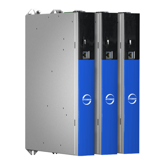
Stober SR6 Commissioning Instructions (96 pages)
Drive controller
Brand:
Stober
| Category:
Controller
| Size: 5 MB
Table of Contents
Table of Contents
2
Foreword
6
User Information
7
Scope of Documentation
7
Storage and Transfer
7
Described Product
7
UL File Number
8
Timeliness
8
Original Language
8
Limitation of Liability
8
Formatting Conventions
9
Use of Symbols
9
Markup of Text Elements
10
Mathematics and Formulas
10
Symbols, Marks and Test Symbols
11
Trademarks
11
General Safety Instructions
12
Directives and Standards
12
Qualified Personnel
12
Intended Use
13
Transport and Storage
13
Operational Environment and Operation
14
Working on the Machine
14
Decommissioning
15
Disposal
15
Firefighting
15
UL-Compliant Use
16
Technical Data
18
Drive Controllers
18
General Technical Data
18
Nameplate
19
Material Variant
20
Type Designation
20
Sizes
21
Electrical Data
22
Dimensions
27
Weight
27
DC Link Connection
28
General Technical Data
28
Assignment of DL6B to SC6
28
Dimensions
29
Weight
29
Safety Technology
30
Controllable Brakes
30
Storage
31
Drive Controllers
31
Annual Reforming
31
Reforming before Commissioning
32
Installation
33
Safety Instructions for Installation
33
Basic Assembly Instructions
33
Drive Controllers
33
Minimum Clearances
34
Drilling Diagrams and Bore Dimensions
35
Drive Controllers
35
Length of Copper Rails
36
Installing the Drive Controller Without a Rear Section Module
37
Installing the DC Link Connection
38
Mounting the Drive Controller on the Rear Section Module
40
Connection
43
Safety Instructions for Connection
43
Line Routing
43
Protective Measures
44
Line Fuse
44
Residual Current Protective Device
46
Protective Grounding
47
EMC Recommendations
50
Drive Controllers
51
Overview
51
X2A: Brake a
52
X2A: Motor Temperature Sensor a
53
X2B: Brake B
53
X2B: Motor Temperature Sensor B
53
X4A: Encoder a
54
X4B: Encoder B
57
X9: Ethernet Service Interface
57
X10: 400 V Supply
58
X11: 24 V Supply
59
X12: Safety Technology (Option SR6)
60
X20A: Motor a
61
X20B: Motor B
62
X21: Braking Resistor
62
X22: DC Link Connection
63
X101: Di1 - Di4
63
X103: Di6 - Di9
64
X200, X201: Ethercat
66
X200, X201: Profinet
67
X300: Brake 24 V Supply
68
X700: SD Slot
68
Connecting a Drive Controller
69
Commissioning
70
Initiating the Project
70
Projecting the Drive Controller and Axis
70
Configuring Safety Technology
72
Creating Other Modules and Drive Controllers
72
Specifying a Module
72
Specifying the Project
72
Mapping the Mechanical Axis Model
73
Parameterizing the STOBER Motor
73
Parameterizing the Axis Model
74
Testing the Project Configuration
77
Replacement
79
Safety Instructions for Device Replacement
79
Replacing the Drive Controller
79
Updating Firmware
81
Replacing or Updating Firmware Using DS6
81
Updating Firmware Using an SD Card
82
Changing the Fieldbus Using DS6
83
Appendix
84
Terminal Specifications
84
Overview
84
Bcf 3,81 180 Sn
85
Bldf 5.08 180 Sn
86
Ispc 5 -Stgcl-7,62
88
Wiring Examples
89
Stand-Alone Operation with Direct Brake Control
89
Order Overview of the Hardware Components
90
Detailed Information
91
Symbols in Formulas
92
Abbreviations
93
Contact
94
Consultation, Service and Address
94
Your Opinion Is Important to Us
94
Close to Customers Around the World
95
Advertisement
Advertisement
Related Products
Stober SD6 Series
Stober SD6A06
Stober SD6A02
Stober SD6A14
Stober SD6A24
Stober SD6A38
Stober SD6A36
Stober SC6A062
Stober SC6A261
Stober SD6A06TEX
Stober Categories
Engine
Controller
Inverter
DC Drives
Industrial Equipment
More Stober Manuals
Login
Sign In
OR
Sign in with Facebook
Sign in with Google
Upload manual
Upload from disk
Upload from URL