ST STM32L4P5G-DK Manuals
Manuals and User Guides for ST STM32L4P5G-DK. We have 2 ST STM32L4P5G-DK manuals available for free PDF download: User Manual
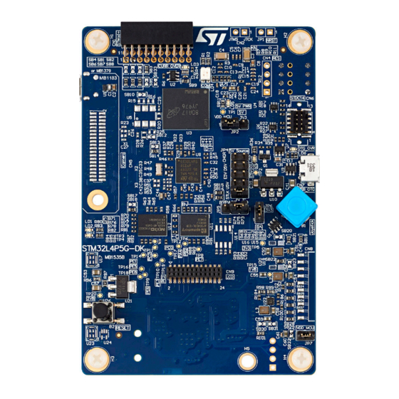
ST STM32L4P5G-DK User Manual (37 pages)
Brand: ST
|
Category: Motherboard
|
Size: 2 MB
Table of Contents
Advertisement
ST STM32L4P5G-DK User Manual (37 pages)
Discovery kit
Brand: ST
|
Category: Network Hardware
|
Size: 4 MB
Advertisement