Sign In
Upload
Manuals
Brands
ST Manuals
Receiver
STEVAL-WLC38RX
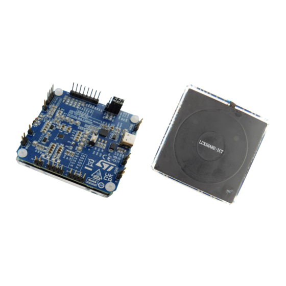
ST STEVAL-WLC38RX Wireless Power Receiver Manuals
Manuals and User Guides for ST STEVAL-WLC38RX Wireless Power Receiver. We have
1
ST STEVAL-WLC38RX Wireless Power Receiver manual available for free PDF download: Getting Started
ST STEVAL-WLC38RX Getting Started (81 pages)
wireless power receiver evaluation board for 5 W Qi BPP and 15 W Qi EPP applications
Brand:
ST
| Category:
Receiver
| Size: 15 MB
Table of Contents
Figure 1. STEVAL-WLC38RX Evaluation Board
1
Get Started
2
Reference Design Specifications
3
Table 1. Reference Design Specifications
3
Overview of the Board
4
Figure 2. Main Board Elements
4
Test Points
5
Table 2. Header and Test Point Descriptions
5
Figure 3. Headers and Test Points
5
Basic Operating Modes
6
Functional Check
6
Figure 4. Transmitter and Receiver Boards Setup
6
Graphical User Interface (GUI)
7
Connecting STWLC38 to PC GUI
7
Figure 5. PC GUI Main Screen
7
Patch and Configuration Files
8
Configuration File Generation
8
Figure 6. Device Selection and Connection
8
Figure 7. Save RX Button
9
Figure 8. Configuration ID Field
9
Header File
10
Header File Generation
10
Figure 9. Save Folder Selection
10
Figure 10. Device Selection
10
Figure 11. Confirmation of Patch Version
11
Figure 12. Header File Save
11
Programming the Device
12
Figure 13. Loading the Header File
12
Figure 14. Loading the Patch and Configuration Files
13
Device Description and Operation
14
System Block Diagram
14
Figure 15. STWLC38 System Block Diagram
14
Integrated Power Rectifier
15
Internal ADC Channels Monitor
15
Main LDO Regulator
15
Figure 16. PC GUI Charts
15
Chip under Voltage Lockout
16
Chip Enable
16
Power up Sequence
16
Ldos
16
Protections Overview
16
Soft Overvoltage Protection (SOVP)
18
Figure 17. SOVP Rx Protection Threshold Setting
18
Hard Overvoltage Protection (HOVP)
19
Figure 18. SOVP Rx Protection Settings
19
Figure 19. HOVP Rx Protection Threshold Setting
19
Figure 20. HOVP Rx Protection Settings
20
Figure 21. VRECT and OVP Thresholds
20
Firmware OVP
21
Overcurrent Protections (OCP)
21
Figure 22. Firmware Rx Protection Threshold Setting
21
Figure 23. Firmware Rx Protection Settings
21
Figure 24. over Current Protection Threshold Setting
22
Figure 25. Hardware Overcurrent Rx Protection Selection
22
Overtemperature Protections (OVTP)
23
Figure 26. Firmware Overcurrent Rx Protection Threshold Setting
23
Figure 27. Firmware Overcurrent Rx Protection Settings
23
Figure 28. Hardware Overtemperature Rx Protection Threshold Setting
24
Figure 29. Hardware Overtemperature Rx Protection Settings
24
NTC Protection
25
Figure 30. Firmware Overtemperature Rx Protection Threshold Setting
25
Figure 31. Firmware Overtemperature Rx Protection Settings
25
Foreign Object Detection (FOD)
26
Figure 32. NTC Rx Protection Threshold Setting
26
Figure 33. NTC Rx Protection Settings NTC ADC
26
WPC Qi Wireless Power Transfer
27
Wireless Power Interface
27
Qi Baseline Power Profile
28
Figure 34. Qi Baseline Power Profile Flowchart
28
Qi Extended Power Profile (EPP)
29
Bidirectional Communication
29
Figure 35. Qi Extended Power Profile Flowchart
29
ASK Communication
30
Table 3. HI and lo State Parameters
30
Figure 36. HI and lo States in ASK Communication
30
Figure 37. Example of a Differential Bi-Phase Encoding Scheme
31
Figure 38. Example of Asynchronous Serial Format
31
FSK Communication
32
Figure 39. ASK Modulation Capacitor Connections
32
Figure 40. Example of Differential Bi-Phase Encoding
32
Most Common Qi Communication Packets
33
Figure 41. Format of Three Defined Responses
33
Adaptive Rectifier Configuration (ARC) Mode
34
Table 4. EPT Codes
34
I²C Interface
35
Table 5. Possible Separation Without and with ARC Mode
35
Figure 42. STEVAL-WBC86TX and STEVAL-WLC38RX Setup
35
Data Validity
36
Start and Stop Conditions
36
Byte Format
36
Interface Protocol
36
Writing to a Single Register
36
Figure 43. Writing to a Single I²C Register
36
Writing to Multiple Registers with Incremental Addressing
37
Reading from a Single Register
37
Reading from Multiple Registers with Incremental Addressing
37
Figure 44. Writing to Multiple I²C Registers
37
Figure 45. Reading from a Single I²C Register
37
Figure 46. Reading from Multiple I²C Registers
37
Gpiox and INTB Pins
38
Interrupt Registers
38
Table 6. GPIO Pins
38
Figure 47. Interrupt Register Settings
39
Schematic Diagrams
40
Figure 48. STEVAL-WLC38RX Circuit Schematic
40
Bill of Material (BOM)
41
Table 7. STEVAL-WLC38RX BOM
41
STEVAL-WLC38RX Description and Operation
43
STEVAL-WLC38RX Coil Description
43
Table 8. Electrical Characteristics of the Receiver Coil
43
Figure 49. Mechanical Characteristics of the Receiver Coil 1
43
Figure 50. Mechanical Characteristics of the Receiver Coil 2
44
Figure 51. Mechanical Characteristics of the Receiver Coil 3
44
STEVAL-WLC38RX PCB Layout
45
Figure 52. STEVAL-WLC38RX PCB Layout Top Layer
45
Figure 53. STEVAL-WLC38RX PCB Layout Inner 1 Layer
46
Figure 54. STEVAL-WLC38RX PCB Layout Inner 2 Layer
47
STWLC38 Default Configuration
48
Table 9. STWLC38 Default Configuration
48
Figure 55. STEVAL-WLC38RX PCB Layout Bottom Layer
48
Typical Performance Characteristics
49
Power up Waveforms
49
Table 10. Typical Performance Characteristics
49
Efficiency and Spatial Freedom in the XY Plane
50
Figure 56. Power up Waveforms of a STEVAL-WLC38RX and STEVAL-WBC86TX Setup
50
Spatial Freedom in the Z-Axis
51
Figure 57. Efficiency Curves for Various Misalignments in the X-Axis
51
Table 11. Maximum Power for Z-Axis Gaps
52
Figure 58. Efficiency Curves for Various Misalignments in the Z-Axis
52
Thermal Performance
53
Figure 59. STEVAL-WLC38RX Communication Performance at High Z Distances
53
Figure 60. Thermal Performance with a 5 W Load (5 V/1 A) after 5 Minutes
53
Figure 61. Thermal Performance with a 15 W Load (9 V/1.7 A) after 5 Minutes
54
Designing a 5 W Qi BPP or 15 W Qi EPP Wireless Power Receiver Based on
55
STEVAL-WLC38RX Evaluation Board
55
External Component Design
55
Coil Selection
55
Series and Parallel Resonant Capacitor Selection
55
VRECT and VOUT Capacitor Selection
55
ASK Modulation Capacitor Selection and Configuration
55
Table 12. Default STWLC38 ASK Configuration
56
Figure 62. Rx ASK Configuration
56
SOVP Clamp Resistor Selection
57
ESD/TVS Diodes
57
NTC Thermistor Connection
57
Figure 63. the Transition from Low Current to Normal Current and the Effect on Modulation
57
PCB Layout Guidelines
58
LDO Output Voltage Configuration
58
Figure 64. External NTC Connection
58
Figure 65. Default LDO Configuration
59
Figure 66. Default LDO Drop Curve
59
FOD Tuning
60
Bpp
60
Figure 67. Cleared Rx FOD Tuning Registers
60
Figure 68. FOD Tuning Tab
60
Figure 69. Load Adjustment
61
Figure 70. Rx/Tx Power Difference Curve
61
Figure 71. Tuning to Obtain a Flat BPP FOD Curve
62
Figure 72. Compensated Values
62
Epp
63
Figure 73. Cleared EPP FOD Settings
63
Figure 74. Tuning to Obtain a Flat EPP FOD Curve
63
Reference Code with STM32 Development Boards
64
Hardware Requirements
64
Hardware Connections
64
Software Requirements
64
Figure 75. Rf - Qf
64
Figure 76. Pin Connection between Host and STWLC38 Chip/Evaluation Board
64
Source Files
65
Reference Code Porting Procedure
65
Api
66
Table 13. Stwlc38_Write_Fwreg
66
Table 14. Stwlc38_Read_Fwreg
66
Table 15. Stwlc38_Get_Chip_Info
66
Table 16. Stwlc38_Fw_Update
66
Error Codes
67
Common Testing and Debugging Issues
67
Table 17. Error Codes and Descriptions
67
Table 18. Common Issues and Causes
67
Board Versions
68
Table 19. STEVAL-WLC38RX Versions
68
Qi Certification
69
Figure 77. Qi Certification Flowchart
69
Regulatory Compliance Information
70
Appendix
71
Figure 78. Temperature before Power Transfer Maximum 25⁰C on STEVAL-WBC86TX
71
Figure 79. Maximum Temperature of the Board after 2Hours (40.8⁰C) - 5W Power Transfer STEVAL-WLC38RX
72
Figure 80. Maximum Temperature of the Board after 2Hours (42.5⁰C) - 5W Power Transfer
72
Figure 81. Maximum Temperature of the Board and Plastic Case after 2Hours (33.5⁰C) - 5W Power Transfer
73
Revision History
74
Table 20. Document Revision History
74
Advertisement
Advertisement
Related Products
ST STDES-WLC38WA
ST STEVAL-WESU1
ST STEVAL-WBC86TX
ST STEVAL-WBC2TX70
ST STEVAL-WBC2TX50
ST STEVAL-WLC99RX
ST STEVAL-L6982NDR
ST STEVAL-IFS013V2
ST STEVAL-PCC010V1
ST STEVAL-6986YT2DL
ST Categories
Motherboard
Computer Hardware
Microcontrollers
Control Unit
Controller
More ST Manuals
Login
Sign In
OR
Sign in with Facebook
Sign in with Google
Upload manual
Upload from disk
Upload from URL