Table of Contents
Advertisement
Getting started with the STEVAL-WLC38RX wireless power receiver evaluation
Introduction
The
STEVAL-WLC38RX
evaluation board is based on
allows users to quickly start their 5W Qi-BPP and 15W Qi-EPP compatible wireless charging receiver projects.
The
STWLC38
wireless power receiver can manage up to 15 W of power according to the Wireless Power Consortium's
Extended Power Profile (EPP).
The integrated circuit requires only a few external components and offers high design flexibility. Using an on-board USB-to-I
bridge, the user can monitor and control the
STEVAL-WLC38RX
includes several safety mechanisms providing overtemperature (OVTP), overcurrent (OCP) and
overvoltage (OVP) protections as well as foreign object detection (FOD) for reliable designs.
UM3154 - Rev 2 - September 2023
For further information contact your local STMicroelectronics sales office.
board for 5 W Qi BPP and 15 W Qi EPP applications
STWLC38
and is designed for wireless power receiver applications. It
STWLC38
using the
STSW-WPSTUDIO
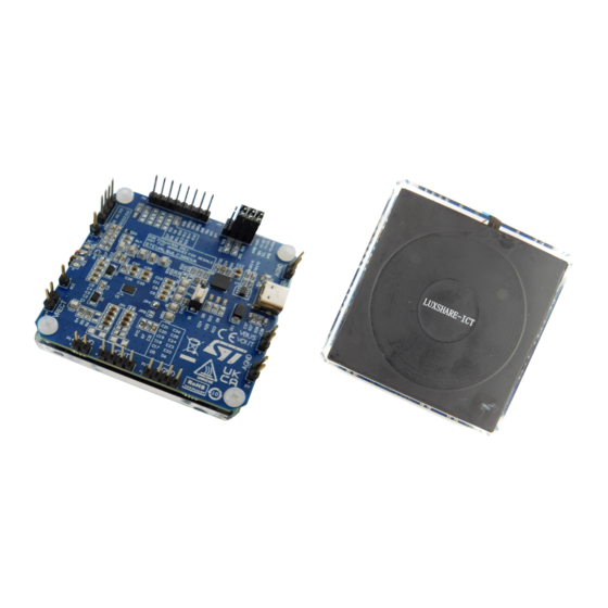
Figure 1.
STEVAL-WLC38RX evaluation board
UM3154
User manual
graphical user interface (GUI).
2
C
www.st.com
Advertisement
Table of Contents

Related Manuals for ST STEVAL-WLC38RX

Summary of Contents for ST STEVAL-WLC38RX
-
Page 1: Figure 1. Steval-Wlc38Rx Evaluation Board
UM3154 User manual Getting started with the STEVAL-WLC38RX wireless power receiver evaluation board for 5 W Qi BPP and 15 W Qi EPP applications Introduction STEVAL-WLC38RX evaluation board is based on STWLC38 and is designed for wireless power receiver applications. It allows users to quickly start their 5W Qi-BPP and 15W Qi-EPP compatible wireless charging receiver projects. -
Page 2: Get Started
UM3154 Get started Get started To get started with STEVAL-WLC38RX, you will need the following items to use the reference design kit: • Evaluation kit components: – STEVAL-WLC38RX board • Additional hardware – STEVAL-WBC86TX for the best results for a 5 W turnkey wireless charging system or any other Qi BPP or Qi EPP compliant transmitter available on the market –... -
Page 3: Reference Design Specifications
UM3154 Reference design specifications Reference design specifications Target specifications of STEVAL-WLC38RX evaluation board are as follows: Table 1. reference design specifications Parameter Description Qi compatibility Qi 1.3 BPP and EPP protocol Rx application PCB area 24 mm x 34 mm Inductance 8 uH, DCR 190 mΩ, ACR 225 mΩ... -
Page 4: Overview Of The Board
UM3154 Overview of the Board Overview of the Board The STEVAL-WLC38RX evaluation board is optimized for performance. The board features: • STWLC38 wireless power receiver chip with BPP and EPP compliant firmware • Very few external components, optimized BOM and PCB space •... -
Page 5: Test Points
UM3154 Test points Test points STEVAL-WLC38RX features several headers and test points to provide easy access to key signals. Figure 3. Headers and test points Table 2. header and test point descriptions Connector Name Description 4-pin Header: for mounting External RX Coil: Rx Coil Pin 1,2 AC2;... -
Page 6: Basic Operating Modes
UM3154 Basic operating modes Connector Name Description USB-C USB-C Connector Basic operating modes The receiver generally works in two modes - DC (also called Standalone) mode and AC mode. DC mode is characterized by the wireless receiver being powered from a DC power supply such as external power supply or USB. -
Page 7: Graphical User Interface (Gui)
Graphical user interface (GUI) Graphical user interface (GUI) STWLC38 (and other ST wireless charging devices) can be configured using the STCHARGE Wireless Power Studio GUI (STSW-WPSSTUDIO). The GUI can also be used to control, monitor and program the device. For more information, please see STCHARGE Wireless Power Studio User Manual. -
Page 8: Patch And Configuration Files
UM3154 Patch and configuration files Step 4. Select [WLC38] as the Rx and click the [Connect] button on the right side of the window. Figure 6. Device selection and connection Patch and configuration files Firmware of the device can be updated using a Patch file (a binary file in .memh format). The latest version of the Patch can be found at STWLC38. -
Page 9: Figure 7. Save Rx Button
UM3154 Configuration file generation Step 3. Click the [Save RX] button in the RX Registers tab or the Common registers tab. Figure 7. Save RX button Step 4. Enter a Configuration ID number (used for version control) and press [OK]. Figure 8. -
Page 10: Header File
UM3154 Header file Step 5. Choose your location for the save file. After choosing a location, the configuration will be saved as a .memh file in the selected folder. Figure 9. Save folder selection Header file The GUI can also be used to generate a Header file, a binary .h file containing both Configuration and Patch files. The Header file makes programming the device using a host MCU easier, as both Configuration and Patch can be loaded at once by simply including the Header file in the host code. -
Page 11: Figure 11. Confirmation Of Patch Version
UM3154 Header file generation Step 2. Continue by selecting the patch and configuration files and press [Generate]. A pop-up window will appear, asking to confirm you have selected the correct Patch version. Figure 11. Confirmation of patch version Step 3. Choose a save destination. -
Page 12: Programming The Device
UM3154 Programming the device Programming the device To program the device, the device must be switched into a so-called DC mode. Before switching to DC mode, first make sure power transfer is not active. The simplest way to achieve this is to either remove the receiver from the transmitter or to power down the transmitter. -
Page 13: Figure 14. Loading The Patch And Configuration Files
UM3154 Programming the device Step 6. Select WLC38 in the top menu and [MEMH] in the toggle selector. Figure 14. Loading the patch and configuration files Step 7. Select the patch and configuration files you want to write. Step 8. Press the [Write] button to load the .memh files into the device. -
Page 14: Device Description And Operation
UM3154 Device description and operation Device description and operation System block diagram Figure 15. STWLC38 system block diagram UM3154 - Rev 2 page 14/81... -
Page 15: Integrated Power Rectifier
UM3154 Integrated power rectifier Integrated power rectifier The synchronous rectifier is a key block in charge of converting the AC power signal from the receiving coil into a DC supply rail for the following linear regulator. The rectifier consists of four N-channel MOSFET transistors arranged into an H-bridge, conveniently driven by a control block that monitors the voltage at the AC1 and AC2 pins to optimize the commutations and to charge the external bootstrap capacitors for the high-side switches. -
Page 16: Chip Under Voltage Lockout
The communication will also not be initialized if either the Patch or Configuration or both files are corrupted. During the initial phase of the power transfer STWLC38 operates in ARC mode, ST’s proprietary mode, which makes the power-up sequence smoother and more reliable. For more information, see Section 5.12 Adaptive... - Page 17 UM3154 Protections overview Overvoltage protections (OVP) • Ping overvoltage protection (POVP) – Protects the device against excessive rectifier voltage (VRECT) during the ping phase (first few milliseconds after the power-up) – The threshold is set to 14 V and is released as soon as the rectifier voltage drops below 11 V. –...
-
Page 18: Soft Overvoltage Protection (Sovp)
UM3154 Protections overview • Hardware thermal shutdown (TSHUT) – Can be configured to disable VOUT when triggered – The threshold can be set from 105 to 135 °C with a 10 °C step. • Firmware OVTP – Can be configured to disable VOUT when triggered –... -
Page 19: Hard Overvoltage Protection (Hovp)
UM3154 Protections overview Figure 18. SOVP Rx protection settings 5.9.2 Hard overvoltage protection (HOVP) HOVP is the fastest (hardware) over-voltage protection, which prevents the rectifier voltage from rising above a safe level. The default threshold value is 18 V. Triggering the protection causes STWLC38 to short AC1 and AC2 to ground, effectively shorting the receiving coil. -
Page 20: Figure 20. Hovp Rx Protection Settings
UM3154 Protections overview Figure 20. HOVP Rx protection settings SOVP enabled, the VRECT voltage oscillates between the HOVP trigger threshold (18 V) and SOVP threshold. Figure 21. VRECT and OVP thresholds UM3154 - Rev 2 page 20/81... -
Page 21: Firmware Ovp
UM3154 Protections overview 5.9.3 Firmware OVP Firmware OVP is the slowest overvoltage protection. Therefore, it is recommended to set its threshold as the lowest among the available over-voltage protections. It monitors the rectifier voltage and can be configured to disable the device’s output and/or force the receiver to send an EPT packet when triggered. The threshold can be adjusted from 0 to 16 V. -
Page 22: Figure 24. Over Current Protection Threshold Setting
UM3154 Protections overview The hardware OCP causes the set action as send EPT or disable Vout. This protection is triggered by HW. The threshold can be set to either 1.25, 1.5, 1.75 or 1.93 A. Figure 24. Over current protection threshold setting Figure 25. -
Page 23: Overtemperature Protections (Ovtp)
UM3154 Protections overview Figure 26. Firmware overcurrent Rx protection threshold setting Figure 27. Firmware overcurrent Rx protection settings 5.9.5 Overtemperature protections (OVTP) The STWLC38 IC is equipped with one overtemperature protection operated by hardware and one managed by the firmware. The hardware OVTP (called TSHUT) causes the AC1 and AC2 pins to be shorted to ground when triggered. -
Page 24: Figure 28. Hardware Overtemperature Rx Protection Threshold Setting
UM3154 Protections overview Figure 28. Hardware overtemperature Rx protection threshold setting Hardware OVTP can also be configured to disable the device output and/or force the receiver to send an EPT packet when triggered. Figure 29. Hardware overtemperature Rx protection settings The firmware OVTP can be adjusted from 0 °C to 200 °C (with a 0.1 °C step) and can be accessed in the GUI or by a host controller. -
Page 25: Ntc Protection
UM3154 Protections overview Figure 30. Firmware overtemperature Rx protection threshold setting Firmware OVTP can also be configured to disable the device output and/or force the receiver to send an EPT packet when triggered. Figure 31. Firmware overtemperature Rx protection settings 5.9.6 NTC protection An external NTC can be used to further monitor the operational temperature of the board. -
Page 26: Foreign Object Detection (Fod)
UM3154 Protections overview The protection can also be configured to disable the device output and/or force the receiver to send an EPT packet when triggered. Figure 32. NTC Rx protection threshold setting Figure 33. NTC Rx protection settings NTC ADC 5.9.7 Foreign object detection (FOD) Foreign object is any object placed either on or near the transmitting coil, which is not considered a valid wireless... -
Page 27: Wpc Qi Wireless Power Transfer
UM3154 WPC Qi wireless power transfer One of the most common ways is estimating the amount of power lost in the system. The power receiver indicates the total amount of received power from the power transmitter. This power consists of power available to the load and power loss which occurs on the supporting circuitry. -
Page 28: Qi Baseline Power Profile
UM3154 WPC Qi wireless power transfer 5.10.2 Qi Baseline Power Profile The flowchart in the figure below shows steps required to achieve power transfer in the Baseline Power Profile (BPP) according to Qi 1.2.4. Figure 34. Qi Baseline Power Profile flowchart •... -
Page 29: Qi Extended Power Profile (Epp)
UM3154 Bidirectional communication 5.10.3 Qi Extended Power Profile (EPP) Extended Power Profile (EPP) is another wireless power transfer profile described by the Qi specification and is used to deliver up to 15 W of power. To enter EPP, both the transmitter and the receiver must comply with the Qi EPP specification. -
Page 30: Ask Communication
UM3154 Bidirectional communication 5.11.1 ASK communication A state (either HI or LO) is characterized by the amplitude being constant (with a certain variation Δ) for at least 150 ms. If the power receiver and power transmitter coils are properly aligned, then for all appropriate loads, at least one of the following three conditions shall apply. -
Page 31: Figure 37. Example Of A Differential Bi-Phase Encoding Scheme
UM3154 Bidirectional communication Figure 37. Example of a differential bi-phase encoding scheme To transmit a single byte of data, the power receiver must send an 11-bit sequence. This sequence consists of a START bit (ZERO), the 8 data bits of the byte (LSB first), a parity bit and a STOP bit (ONE). The parity is odd, meaning an even number of ONE bits in the data byte results in the parity bit being equal to ONE, while an odd number of ONE bits in the data byte results in the parity bit being equal to ZERO. -
Page 32: Fsk Communication
UM3154 Bidirectional communication Figure 39. ASK modulation capacitor connections 5.11.1.1 ASK communication example: sending a proprietary packet from STWLC38 to STWBC86 The explanation of ASK communication is described in detail in Bi-directional communication application note on STWLC38 and STWBC86. 5.11.2 FSK communication The power transmitter modulates the power signal by switching between its normal operating frequency f and its... -
Page 33: Most Common Qi Communication Packets
UM3154 Bidirectional communication Each data byte is transferred as a sequence of 11-bits. The sequence consists of a start bit (ZERO), the data byte itself, a parity bit and a stop bit (ONE). The parity used for byte encoding is even – the parity bit set to a ONE if the data byte contains an odd number of ONE bits. -
Page 34: Adaptive Rectifier Configuration (Arc) Mode
UM3154 Adaptive rectifier configuration (ARC) mode • End power transfer (EPT) is used by the power receiver to request power transfer termination. The power transmitter shall terminate the power transfer immediately after receiving an EPT packet. The EPT packet should contain a message indicating the reason for the termination. The following table lists the codes used for various reasons. -
Page 35: I²C Interface
I²C Interface Figure 42. STEVAL-WBC86TX and STEVAL-WLC38RX setup The ARC mode is dedicated rectifier setting what allows to increase the spatial freedom of position. The ARC mode is automatically enabled and the IC stays in ARC mode until the Vrect exceeds the set threshold (RX ARC THRES). -
Page 36: Data Validity
UM3154 I²C Interface The pins are up to 3.3 V tolerant, and the pull-up resistors should be selected as a trade-off between communication speed (lower resistors lead to faster edges) and data integrity (the input logic levels must be guaranteed to preserve communication reliability). When the bus is idle, both SDA and SCL lines are pulled HIGH. -
Page 37: Writing To Multiple Registers With Incremental Addressing
UM3154 I²C Interface 5.13.6 Writing to multiple registers with incremental addressing STWLC38 supports writing to multiple registers with auto-incremental addressing. When data is written into a register, the register pointer is automatically incremented, therefore transferring data to a set of subsequent registers (also known as page write) is a straightforward operation. -
Page 38: Gpiox And Intb Pins
UM3154 GPIOx and INTB pins 5.14 GPIOx and INTB pins GPIO0 through GPIO2 are programmable general-purpose I/O pins. These pins can be configured as inputs or outputs (push-pull or open-drain) and assigned various functions. Table 6. GPIO pins Code Function 0x01 Pull-up 0x02... -
Page 39: Figure 47. Interrupt Register Settings
UM3154 Interrupt registers Figure 47. Interrupt register settings UM3154 - Rev 2 page 39/81... -
Page 40: Schematic Diagrams
UM3154 Schematic diagrams Schematic diagrams Figure 48. STEVAL-WLC38RX circuit schematic UM3154 - Rev 2 page 40/81... -
Page 41: Bill Of Material (Bom)
UM3154 Bill of material (BOM) Bill of material (BOM) Table 7. STEVAL-WLC38RX BOM Item Q.ty Ref. Value Description Manufacturer Order code TP1, TP2, TP3, TP4, TP5, TP6, TEST POINT Harwin S2751-46R TP7, TP8, TP9, TP10, TP11 C1, C2, C3, C4, C21, C26, C28,... - Page 42 UM3154 Bill of material (BOM) Item Q.ty Ref. Value Description Manufacturer Order code Header 4 Luxshare LD81FP008-1H Header 4X2 Harwin M20-9980445 Header 8 Harwin M20-9730845 SMD 0603 RES Panasonic ERJ-3GEYJ682V 220k SMD 0603 RES Panasonic ERJ-3GEYJ224V N.M. SMD 0805 RES N.M.
-
Page 43: Steval-Wlc38Rx Description And Operation
UM3154 STEVAL-WLC38RX description and operation STEVAL-WLC38RX description and operation STEVAL-WLC38RX coil description Table 8. Electrical characteristics of the receiver coil Parameter Specification Part number LD81FP008-1H Vendor Luxshare-ICT Inductance (@ 100 kHz) 8 +/- 0.2 µH DC resistance (DCR) 190mΩ (±10%) AC resistance (ACR) 225mΩ... -
Page 44: Figure 50. Mechanical Characteristics Of The Receiver Coil 2
UM3154 STEVAL-WLC38RX coil description Figure 50. Mechanical characteristics of the receiver coil 2 Figure 51. Mechanical characteristics of the receiver coil 3 UM3154 - Rev 2 page 44/81... -
Page 45: Steval-Wlc38Rx Pcb Layout
UM3154 STEVAL-WLC38RX PCB layout STEVAL-WLC38RX PCB layout Figure 52. STEVAL-WLC38RX PCB layout top layer UM3154 - Rev 2 page 45/81... -
Page 46: Figure 53. Steval-Wlc38Rx Pcb Layout Inner 1 Layer
UM3154 STEVAL-WLC38RX PCB layout Figure 53. STEVAL-WLC38RX PCB layout inner 1 layer UM3154 - Rev 2 page 46/81... -
Page 47: Figure 54. Steval-Wlc38Rx Pcb Layout Inner 2 Layer
UM3154 STEVAL-WLC38RX PCB layout Figure 54. STEVAL-WLC38RX PCB layout inner 2 layer UM3154 - Rev 2 page 47/81... -
Page 48: Stwlc38 Default Configuration
UM3154 STWLC38 default configuration Figure 55. STEVAL-WLC38RX PCB layout bottom layer STWLC38 default configuration Table 9. STWLC38 default configuration Parameter Value Output voltage (BPP mode, 5 W) Output voltage (EPP mode, 15 W) half-sync up to 160 mA Rectifier mode... -
Page 49: Typical Performance Characteristics
UM3154 Typical performance characteristics Parameter Value Software over-current protection (SW OCP) 1.75 A Soft over-voltage protection (SOVP) 16 V Software over-temperature protection (SW OVTP) 85 °C Hardware over-temperature protection (TSHUT) 105 °C Iload 32 mA ARC mode disable threshold Vrect ready threshold (Vout is enabled) Vout setting + 240 mV Manufacturer ID 0x0022... -
Page 50: Efficiency And Spatial Freedom In The Xy Plane
Efficiency and spatial freedom of STEVAL-WLC38RX were measured with STEVAL-WBC86TX as the transmitter. The efficiency was measured from the transmitter DC input to the receiver DC output. The measurement does not include any power losses in the wall adapter or the cable. -
Page 51: Spatial Freedom In The Z-Axis
Z-axis distance between the coils, also known as charging gap, is an additional parameter which significantly affects charging performance. Therefore, STEVAL-WLC38RX was also tested at various charging gap distances. The measurements examined two key performance indicators – efficiency and maximum delivered power. -
Page 52: Table 11. Maximum Power For Z-Axis Gaps
UM3154 Typical performance characteristics Figure 58. Efficiency curves for various misalignments in the Z-axis Table 11. maximum power for Z-axis gaps Z gap [mm] Maximum power(1) [W] 5.002 5.000 5.001 5.000 5.000 3.093 (1) The maximum power is also limited by the transmitter, as STEVAL-WBC86TX is only BPP compatible ARC mode also improves performance at higher Z-axis distances. -
Page 53: Thermal Performance
UM3154 Typical performance characteristics Figure 59. STEVAL-WLC38RX communication performance at high Z distances YELLOW→VRECT, BLUE→VOUT, RED -> AC1 8.4.4 Thermal performance Figure 60. Thermal performance with a 5 W load (5 V/1 A) after 5 minutes UM3154 - Rev 2... -
Page 54: Figure 61. Thermal Performance With A 15 W Load (9 V/1.7 A) After 5 Minutes
UM3154 Typical performance characteristics Figure 61. Thermal performance with a 15 W load (9 V/1.7 A) after 5 minutes UM3154 - Rev 2 page 54/81... -
Page 55: Designing A 5 W Qi Bpp Or 15 W Qi Epp Wireless Power Receiver Based On
UM3154 Designing a 5 W Qi BPP or 15 W Qi EPP wireless power receiver based on STEVAL-WLC38RX evaluation board Designing a 5 W Qi BPP or 15 W Qi EPP wireless power receiver based on STEVAL-WLC38RX evaluation board The design should begin with external component selection, as those components have a significant impact on the board performance. -
Page 56: Table 12. Default Stwlc38 Ask Configuration
UM3154 External component design The modulation capacitors used in STEVAL-WLC38RX were chosen to ensure good communication performance under all operating conditions. Using a custom board design may require changing the COMA and COMB capacitors. The COMA and COMB capacitors are used for power signal modulation. Although the modulation period is short, the voltage drop it creates across the LDO must be considered, as this drop further increases overall losses of the system. -
Page 57: Sovp Clamp Resistor Selection
UM3154 External component design Figure 63. The transition from Low current to Normal current and the effect on modulation This should be considered when configuring the LDO drop curve (see LDO output voltage configuration). 9.1.5 SOVP clamp resistor selection SOVP clamp resistors, also known as IEXT resistors, are used as a part of the SOVP protection. When triggered, STWLC38 pulls VRECT to ground through those resistors in an attempt to lower the VRECT voltage. -
Page 58: Pcb Layout Guidelines
UM3154 PCB layout guidelines Figure 64. External NTC connection PCB layout guidelines • Power tracks (AC1, AC2, VRECT, VOUT) and power ground tracks should be kept wide enough to sustain high current. Duplicating these tracks in inner layers and adding vias is advisable wherever possible to lower impedance as much as possible. -
Page 59: Figure 65. Default Ldo Configuration
UM3154 LDO output voltage configuration Figure 65. Default LDO configuration Figure 66. Default LDO drop curve UM3154 - Rev 2 page 59/81... -
Page 60: Fod Tuning
UM3154 FOD tuning FOD tuning The aim of this tuning is to provide instructions and a step-by-step example of how to fine-tune STWLC38 parameters to comply with Qi requirements regarding foreign object detection. Note: In the final product FOD tuning procedure requires a calibrated, Qi-compliant transmitter (like Nok9 system, GRL, etc.) capable of reporting both the transmitted power and received power (sent back from the receiver under test) without terminating the power transfer in case a FOD condition is detected. -
Page 61: Figure 69. Load Adjustment
UM3154 FOD tuning Step 6. Increase the load from 0 to 1000 mA in 100 mA steps (in case of a 5 W setup) and record the Prx and Ptx values (use the [+] button to add more lines). The Qi standard allows up to 350 mW difference between Prx and Ptx. The default target of the tool is set to 200 mW (can be adjusted on the right-hand side). -
Page 62: Figure 71. Tuning To Obtain A Flat Bpp Fod Curve
UM3154 FOD tuning Step 8. Move the sliders on right-hand side to achieve a flat line close the target ΔP. Figure 71. Tuning to obtain a flat BPP FOD curve Step 9. Check the compensated values by navigating back to the first page of the tool. Figure 72. -
Page 63: Epp
UM3154 FOD tuning 9.4.2 Step 1. Begin by navigating to the Rx EPP FOD Configuration section. Step 2. Set all the registers to 0 and generate a new Configuration file. Figure 73. Cleared EPP FOD settings Step 3. Load the file into the device. Step 4. -
Page 64: Reference Code With Stm32 Development Boards
Qi certified EPP transmitter and should be set to the register shown below: Figure 75. Rf - Qf Reference code with STM32 development boards 9.5.1 Hardware requirements STM32 development board (e.g., STM32 Nucleo-144) STEVAL-WLC38RX 9.5.2 Hardware connections Step 1. Connect the STWLC38 I C pins to the master I C bus. -
Page 65: Source Files
Patch and Configuration data in header file format to be programmed into the chip. 9.5.5 Reference code porting procedure Step 1. Create a new project in the STM32CubeIDE with a STM32 development board. Visit the ST website for STM32CubeIDE documentation. Step 2. Copy STWLC38.h, STWLC38.c, and nvm_data.h into the main directory (Core/Src). -
Page 66: Api
UM3154 Reference code with STM32 development boards 9.5.6 9.5.6.1 stwlc38_write_fwreg Table 13. stwlc38_write_fwreg Name int32_t stwlc38_write_fwreg(struct stwlc38_dev *dev, uint16_t reg, const uint8_t *data, int32_t len) Description Write device firmware register. struct stwlc38_dev * Pointer to device interface. uint16_t Register to write Parameters uint8_t * data... -
Page 67: Error Codes
UM3154 Common testing and debugging issues 9.5.7 Error codes Table 17. Error codes and descriptions Error code Value Description STWLC38_OK 0x00000000U No error STWLC38_ERR_BUS_W 0x80000000U Bus write error STWLC38_ERR_BUS_WR 0x80000001U Bus write-read error STWLC38_ERR_ALLOC_MEM 0x80000002U Failed to allocate memory STWLC38_ERR_INVALID_PARAM 0x80000003U Invalid parameter STWLC38_ERR_TIMEOUT... -
Page 68: Board Versions
UM3154 Board versions Board versions Table 19. STEVAL-WLC38RX versions Finished good Schematic diagrams Bill of materials STEVAL$WLC38RXA STEVAL$WLC38RXA schematic diagrams STEVAL$WLC38RXA bill of materials 1. This code identifies the STEVAL-WLC38RX evaluation board first version. UM3154 - Rev 2 page 68/81... -
Page 69: Qi Certification
UM3154 Qi Certification Qi Certification STWLC38 is Qi 1.3 EPP compatible and can therefore be Qi certified. The following section describes the basic requirements necessary for Qi EPP certification. It should be noted that STWLC38 Extended Power Profile (EPP) Qi compatibility guarantees Baseline Power Profile (BPP) compatibility as EPP is a BPP extension. -
Page 70: Regulatory Compliance Information
Conformity. Notice for the United Kingdom The kit STEVAL-WLC38RX is in compliance with the UK Radio Equipment Regulations 2017 (UK SI 2017 No. 1206 and amendments) and with the Restriction of the Use of Certain Hazardous Substances in Electrical and Electronic Equipment Regulations 2012 (UK SI 2012 No. -
Page 71: Appendix
UM3154 Appendix Appendix Thermal measurements on the Board tested at 25⁰C ambient temperature. Note: The ambient temperature should not exceed 65⁰C. Figure 78. Temperature Before Power Transfer Maximum 25⁰C on STEVAL-WBC86TX UM3154 - Rev 2 page 71/81... -
Page 72: Figure 79. Maximum Temperature Of The Board After 2Hours (40.8⁰C) - 5W Power Transfer Steval-Wlc38Rx
UM3154 Appendix Figure 79. Maximum Temperature of the Board after 2hours (40.8⁰C) – 5W power transfer STEVAL- WLC38RX Figure 80. Maximum Temperature of the Board after 2hours (42.5⁰C) – 5W power transfer UM3154 - Rev 2 page 72/81... -
Page 73: Figure 81. Maximum Temperature Of The Board And Plastic Case After 2Hours (33.5⁰C) - 5W Power Transfer
UM3154 Appendix Figure 81. Maximum Temperature of the Board and Plastic case after 2hours (33.5⁰C) – 5W power transfer UM3154 - Rev 2 page 73/81... -
Page 74: Revision History
UM3154 Revision history Table 20. Document revision history Date Version Changes 17-Jul-2023 Initial release. Updated Section 6 Schematic diagrams, Section 7 Bill of material (BOM). 27-Sep-2023 Minor text changes. UM3154 - Rev 2 page 74/81... -
Page 75: Table Of Contents
UM3154 Contents Contents Get started ............... .2 Reference design specifications . - Page 76 STEVAL-WLC38RX description and operation ........43...
- Page 77 UM3154 Contents LDO output voltage configuration ..........58 FOD tuning.
- Page 78 STEVAL-WLC38RX versions........
- Page 79 STEVAL-WBC86TX and STEVAL-WLC38RX setup........
- Page 80 Figure 59. STEVAL-WLC38RX communication performance at high Z distances ......53 Figure 60.
- Page 81 ST’s terms and conditions of sale in place at the time of order acknowledgment. Purchasers are solely responsible for the choice, selection, and use of ST products and ST assumes no liability for application assistance or the design of purchasers’...
Need help?
Do you have a question about the STEVAL-WLC38RX and is the answer not in the manual?
Questions and answers