Sign In
Upload
Manuals
Brands
ST Manuals
Motherboard
STEVAL-WBC86TX
ST STEVAL-WBC86TX Manuals
Manuals and User Guides for ST STEVAL-WBC86TX. We have
1
ST STEVAL-WBC86TX manual available for free PDF download: User Manual
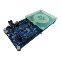
ST STEVAL-WBC86TX User Manual (78 pages)
Wireless power transmitter evaluation board for up to 5 W Qi-BPP applications
Brand:
ST
| Category:
Motherboard
| Size: 7 MB
Table of Contents
Figure 1. STEVAL-WBC86TX Board
1
Reference Design Specifications
3
Table 1. STEVAL-WBC86TX Target Specifications
3
Overview of the Board
4
Figure 2. STEVAL-WBC86TX Evaluation Board Features
4
Test Points
5
Figure 3. Connectors and Test Points
5
Basic Operating Modes
6
Table 2. Connectors and Test Points
6
Graphical User Interface (GUI)
7
Connecting STWBC86 to PC GUI
7
Figure 4. GUI Connection
7
Patch and Configuration Files
8
Figure 5. GUI Device Connection
8
Configuration File Generation
9
Figure 6. Generation of Configuration File
9
Figure 7. Version of the Configuration File
9
Header File
10
Figure 8. Saving of the Configuration File
10
Header File Generation
11
Figure 9. Header Generator - Chip Selection
11
Figure 10. Header Generation - Pop up Window
11
Figure 11. Header Generation - Save Header File
12
Programming the Device
13
Figure 12. Programming the Device by Header File
13
Figure 13. Generating the Header File by Patch and Configuration Files
14
Device Description and Operation
15
System Block Diagram
15
Integrated Power Inverter
15
Figure 14. System Block Diagram
15
Adc
16
Figure 15. H-Bridge Mode Settings
16
Figure 16. GUI Charts Monitoring
16
Ldos
17
Power-Up Sequence
17
Uvlo
17
Chip Reset
17
Protections Overview
17
Overcurrent Protection (OCP)
17
Overvoltage Protection (OVP)
18
Figure 17. OCP Settings
18
Figure 18. OVP Settings
18
Overtemperature Protection (OVTP)
19
Ntc
19
Figure 19. OVTP Settings
19
Figure 20. NTC Connection on Board
20
Figure 21. NTC Settings
20
Foreign Object Detection (FOD)
21
FOD Tuning
21
Figure 22. Disable FO Detection
21
Figure 23. Add a New Dataset
22
Figure 24. Display Dataset in Plot
22
Figure 25. Enable Auto Scroll
22
Figure 26. Additional Dataset Options
23
Figure 27. Line Properties - Dashed/Solid
23
Figure 28. Line Properties - Color
23
Figure 29. Logged Data
24
Figure 30. Delete a Single Data Point
25
Figure 31. Spot Wrong Data Point in Plot
25
Figure 32. Plot Logged Data
26
Figure 33. Ploss Threshold
27
Figure 34. CTC Threshold
27
Figure 35. Unsutiable Parameter Values Highlighted in Red
28
Figure 36. Load Tuned Parameters
29
Figure 37. Enable FOD and Set FOD Debounce
29
EPT Reason
30
Figure 38. EPT Reason
30
Figure 39. Received Message
31
Figure 40. EPT Interrupt Setting
31
WPC Qi Wireless Power Transfer
32
Figure 41. Protection Debounce Setting
32
Figure 42. EPT Reping Settings
32
Wireless Power Interface
33
Bidirectional Communication
33
Figure 43. Power Transfer Start up Sequence
33
ASK Communication
35
Figure 44. Amplitude Modulation of the Power Signal
35
Figure 45. Example of a Differential Bi-Phase Encoding Scheme
36
Figure 46. Example of the Asynchronous Serial Format
36
Figure 47. ASK Communication Example - High Load Current
36
FSK Communication
37
Figure 48. ASK Communication - no Load
37
Figure 49. Example of Differential Bi-Phase Encoding
37
Most Common Qi Communication Packets
38
Figure 50. Format of the Three Defined Responses
38
I2C Interface
39
Data Validity
39
Start and Stop Conditions
39
Byte Format
39
Interface Protocol
39
Writing to a Single Register
39
Writing to Multiple Registers with Incremental Addressing
40
Reading from a Single Register
40
Figure 51. Writing to a Single Register
40
Figure 52. Writing to Multiple Registers
40
Figure 53. Reading from a Single Register
40
Reading from Multiple Registers with Incremental Addressing
41
Gpiox and INTB Pins
41
Interrupt Registers
41
Table 3. GPIO Functions
41
Figure 54. Reading from Multiple Registers
41
Frequency Hopping (Fhop)
42
Figure 55. Interrupt Registers
42
Figure 56. FHOP Settings
43
Figure 57. FHOP Example
43
PID Tuning
44
Figure 58. PID Parameters
44
STEVAL-WBC86TX Description and Operation
45
STWBC86 Default Configuration
45
Table 4. Basic Parameters
45
Typical Performance Characteristics
46
Power-Up Waveforms
46
Table 5. Charging Performance
46
Table 6. Signal Legend for Power up Waveform
46
Figure 59. Power up Waveform
46
Efficiency and Spatial Freedom in the XY Plane
47
Figure 60. X, y Axis for Misalignment
47
Efficiency and Spatial Freedom in the Z-Axis
48
Figure 61. Efficiency Curve in X Axis
48
Figure 62. Efficiency Curve in y Axis
48
Thermal Performance
49
Figure 63. Efficiency Curve in Z Axis
49
Figure 64. Thermal Performance
49
Designing a 5 W Wireless Power Transmitter Based on the STEVAL-WBC86TX
50
Evaluation Board
50
External Component Design
50
Coil Selection
50
Series Resonant Capacitor Selection
50
Vin and Vinv Capacitors Selection
50
Hardware Input Protections
50
Ring Node Voltage Sensing
51
PCB Layout Guidelines
51
Figure 65. Ring Node Voltage Sensing
51
Figure 66. Ring Node Divider Configuration
51
Reference Code with STM32 Development Boards
52
Hardware Requirements
52
Hardware Connections
52
Table 7. Pin Connection between Host (STM32) and STWBC86
52
Figure 67. Pin Connection between Host and STWBC86 Chip/Evaluation Board
52
Software Requirements
53
Source Files
53
Reference Code Porting Procedure
53
Figure 68. Connectivity
53
Api
54
Error Codes
54
Table 8. Error Codes with Descriptions
54
Schematic Diagrams
55
Figure 69. STEVAL-WBC86TX Circuit Schematic (1 of 4)
55
Figure 70. STEVAL-WBC86TX Circuit Schematic (2 of 4)
56
Figure 71. STEVAL-WBC86TX Circuit Schematic (3 of 4)
57
Figure 72. STEVAL-WBC86TX Circuit Schematic (4 of 4)
58
Bill of Materials
59
Table 9. STEVAL-WBC86TX Bill of Materials
59
STEVAL-WBC86TX PCB Layout
62
Figure 73. Top Layer
62
Figure 74. Inner1 Layer
63
Figure 75. Inner2 Layer
64
Figure 76. Bottom Layer
65
Board Versions
66
Table 10. STEVAL-WBC86TX Versions
66
Regulatory Compliance Information
67
Appendix A Thermal Measurements
68
Figure 77. Temperature before Power Transfer Maximum 25⁰C on STEVAL-WBC86TX
68
Figure 78. Maximum Temperature of the Board after 2Hours (40.8⁰C) - 5W Power Transfer STEVAL-WLC38RX
69
Figure 79. Maximum Temperature of the Board and Plastic Case after 2Hours (33.5⁰C) - 5W Power Transfer
70
Revision History
71
Table 11. Document Revision History
71
Table of Contents
72
List of Tables
75
List of Figures
76
Advertisement
Advertisement
Related Products
ST STEVAL-WESU1
ST STEVAL-WBC2TX70
ST STEVAL-WBC2TX50
ST STEVAL-WLC99RX
ST STEVAL-MKI132V1
ST STEVAL-ESC001V1
ST STEVAL-AETKT3V1
ST STEVAL-SMARTAG2
ST STEVAL-IME015V1
ST STEVAL-IHM020V1
ST Categories
Motherboard
Computer Hardware
Microcontrollers
Control Unit
Controller
More ST Manuals
Login
Sign In
OR
Sign in with Facebook
Sign in with Google
Upload manual
Upload from disk
Upload from URL